
Subscribe to Our Youtube Channel
Related Manuals for Beck 42-107


Summary of Contents for Beck 42-107
- Page 1 MODELS 42-107 80-0042-00 Rev. 06.9 42-105 42-103 INSTRUCTION MANUAL E L E C T R I C A C T U A T O R S F O R I N D U S T R I A L P R O C E S S C O N T R O L...
-
Page 2: Table Of Contents
80-0042-00, Rev. 06.9 TABLE OF CONTENTS Product Description ......................3 General Specifications ....................4 Outline Dimensions .......................6 Installation ........................7 Power and Signal Wiring ....................7 Safety Precautions ......................10 Start-up Instructions ....................11 Calibration ........................12 Travel Limit Switch Adjustment ...................12 Setting Auxiliary Switches ...................14 Changing Direction of Travel ..................15 Feedback Signal ......................16 Demand Input Signal....................18... -
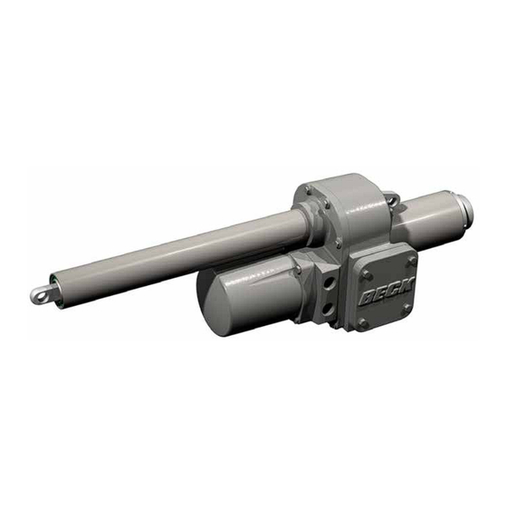
Page 3: Product Description
Class II, Division 2, Groups F & G; T3C requested slot in the Beck family of products. Class III, Division 1 & 2 As with all Beck actuators, the Group 42 is Enclosure type 4X designed for simple installation, no duty cycle... -
Page 4: General Specifications
80-0042-00, Rev. 06.9 PRODUCT DESCRIPTION GENERAL SPECIFICATIONS Actuator Power 120 V ac, single-phase, 50 or 60 Hz Allowable Tolerance +10% / -15% Max. Current & Power 1.2A, 144W @ 120 V ac Output Thrust and Timing 1,000 lbs (4 450 N), 4.2 sec/in (1.65 sec/mm) Stroke Range 5 to 18 inches (127 to 457 mm) Weight... - Page 5 Mounting Orientation Can be mounted in any orientation. Standards* CSA Certified CE Compliant NOTE: May not be available with all options and models. For more information, or to inquire about standards not specifically listed, please call Beck at 215-968-4600.
-
Page 6: Outline Dimensions
80-0042-00, Rev. 06.9 OUTLINE DIMENSION DRAWINGS MODEL 42-107, -105 & -103 SPECIFICATIONS (All dimensions are in inches and [mm] and are subject to change) "L" DIMENSION 3/8 [10] 1 1/16" 3/4" REAR CLEVIS [27] [19] HOLE DIAMETER (SEE TABLE) 11/16"... -
Page 7: Installation
80-0042-00, Rev. 06.9 INSTALLATION POWER AND SIGNAL WIRING The Group 42 actuator has a pair of 3/4" NPT threaded holes for signal and power conduit connection. Conduits should be routed from below the actuator so that condensation and other contaminants flow away from the conduit. - Page 8 80-0042-00, Rev. 06.9 INSTALLATION Option 7, Modulating Analog Position Control with Loop Powered Position Feedback Signal Customer must supply two wires to power the drive: One 120 V ac line (terminal 1), and one neutral (terminal 2). Customer must supply two wires for the analog input control signal: Connect to terminal 11 (-) and to terminal 12 (+).
- Page 9 80-0042-00, Rev. 06.9 Option 5, Modulating Direct AC Control with Loop Powered Position Feedback Signal Customer must supply three wires to directly control the actuator motor direction: One 120 V ac line to run Extend (terminal 10), one 120 V ac line to run Retract (terminal 9), and one neutral (terminal 2). Customer may supply two additional wires to monitor a loop powered position feedback signal.
-
Page 10: Safety Precautions
If there is no wiring diagram available, you UNPACKING may obtain a copy from Beck by providing the serial number of your drive. Group 42 actuators are shipped in standardized... -
Page 11: Start-Up Instructions
80-0042-00, Rev. 06.9 START‑UP INSTRUCTIONS After wiring and mounting, the actuator is ready to be tested for proper operation. Turn on the power supply. For Options 3 & 5, turn on the actuator 120 V ac control signal and observe that the output shaft travels through its desired stroke and moves in the proper direction. -
Page 12: Calibration
5. Disconnect the meter and reconnect switch Control options 5 & 7 (42-105, 42-107): S3 wires and actuator power. and S4 provide electrical over-travel protection. 6. Extend the output shaft away from the retract In these versions, the control electronics position travel limit. - Page 13 80-0042-00, Rev. 06.9 Setting the Extend Travel Limit Switch (S4) 1. Remove the control module cover. 2. Extend the output shaft to the desired travel Cam Adjustment Slots limit. For Options 3 & 5, skip to step 3. For (any one may be used) Option 7: De-energize the motor by turning toggle switch S1 (see Fig.
-
Page 14: Setting Auxiliary Switches
80-0042-00, Rev. 06.9 CALIBRATION SETTING AUXILIARY SWITCHES The following procedure recommends the use of a continuity meter to determine when the (S1 & S2) auxiliary switch opens or closes. If such a meter All versions of Group 42 actuators referenced is not available, it is possible to hear the switch in this manual are shipped with two auxiliary click as the contacts open and close. -
Page 15: Changing Direction Of Travel
80-0042-00, Rev. 06.9 CHANGING OUTPUT SHAFT 6. For extend output shaft travel on an increasing signal, plug P4 must be attached to the DIRECTION OF TRAVEL terminal labeled CW. Note that this is a locking Direction of travel is defined as the direction type plug and must be located properly in its of output shaft travel produced by an increasing receptacle. -
Page 16: Feedback Signal
80-0042-00, Rev. 06.9 CALIBRATION FEEDBACK SIGNAL OPTIONS (OPTIONS 5 & 7 ONLY) The feedback signal is an analog voltage or current signal proportional to the position of the drive’s output shaft. It may be used for remote position indication or for automatic control loop feedback. - Page 17 12 volt zener (Manual), Option 7 Control Board only. diode, Beck Part Number 13-2550-04. See 5. Connect the meter to read the feedback signal. Figure 5, page 16, for location of resistor R2.
-
Page 18: Demand Input Signal
80-0042-00, Rev. 06.9 CALIBRATION Feedback Signal Calibration, cont'd travel, the input signal should be 12 milliamps (3 volts) and at fully retracted, 4 milliamps (1 volt). 15. Position the actuator output shaft to the end Split signal operation is also possible. The of travel limit that corresponds to 20 mA (i.e., control board can be adjusted to produce full to the fully extended position if the actuator... -
Page 19: Loss Of Signal Function
80-0042-00, Rev. 06.9 FOR INSTALLATIONS WITH NO REMOTE 22‑4001‑17 INDICATOR: Remove the resistor from between terminals 13 and 14 and connect the meter across these terminals. Terminal 14 is positive. J5 / J6 5. Connect 120 V ac to terminals 1 and 2. 6. -
Page 20: Deadband Adjustment
Typically, it is best to use the full travel of the (Model 42‑107 Only) actuator in response to the 0–100% Demand The Stall function for Model 42-107 actuators input signal. However, some set-ups and provides protection for the actuator motor and applications make it necessary to reduce this gearing in the event of a stalled condition. -
Page 21: Maintenance
The Group 42 actuator is designed so that Any customer replacement kit may be purchased no field maintenance of the output section for spare parts. Contact your Beck Sales Engineer is required. The gear train and bearings are for recommended replacement parts particular to permanently lubricated and do not require any your application. -
Page 22: Troubleshooting
Fuse F-1 open. No lamps lit on Check for possible shorts, then replace control board. fuse. Use only Beck part no. 11-1370-10 for proper protection of triacs. External auto/man switch in wrong Return switch to auto position. -
Page 23: Services
1) the repair or replacement, without charge, at Beck’s factory, of any defective equipment covered by this warranty, or 2) at Beck’s option, a full refund of the purchase price. In no event will Beck’s liability exceed the contract price for the goods claimed to be defective. - Page 24 HAROLD BECK & SONS, INC. Made in USA 11 TERRY DRIVE NEWTOWN, PENNSYLVANIA 18940 USA PHONE: 215-968-4600 FAX: 215-860-6383 E-MAIL: sales@haroldbeck.com 02/19 www.haroldbeck.com...
Need help?
Do you have a question about the 42-107 and is the answer not in the manual?
Questions and answers