Table of Contents
Advertisement
Quick Links
Advertisement
Table of Contents

Related Manuals for AngioDynamics NanoKnife System


Summary of Contents for AngioDynamics NanoKnife System
- Page 1 NanoKnife System User Manual Version 3.0 16795933-21 REVC - English 2024-03...
- Page 2 NanoKnife System User Manual Copyright © 2024 AngioDynamics. *All trademarks and registered trademarks are the property of their respective owners. *AngioDynamics, the AngioDynamics logo, NanoKnife and the NanoKnife logo are trademarks and/or registered trademarks of AngioDynamics, Inc. and affiliate or a subsidiary.
-
Page 3: Table Of Contents
..................15 Electrode Probe Components ................15 SECTION 4: INSTALLATION AND START-UP ............ 16 Location and Installation ..................16 4.1.1 Installation Instructions ................. 16 NanoKnife Generator Start-Up Self Test ............16 16795933-21 REVC - English NanoKnife System User Manual Version 3.0... - Page 4 How to Delete Probe Pairs from Pulse Parameters Table ......57 7.6.1 7.6.2 How to Add Probe Pairs to the Pulse Parameters Table ......58 Distance Solver ..................... 59 7.7.1 How to use the Distance Solver ..............59 16795933-21 REVC - English NanoKnife System User Manual Version 3.0...
- Page 5 How to Skip Probe Pairs during Pulse Delivery ..........89 8.7.9 8.7.10 Low Current Conditions during Pulse Delivery ..........90 8.7.11 High Current Conditions during Pulse Delivery ..........91 8.7.12 How to Deliver Additional Pulses ..............93 16795933-21 REVC - English NanoKnife System User Manual Version 3.0...
- Page 6 ....................112 SECTION 13: MAINTENANCE & SERVICE ............118 13.1 Overview ....................... 118 13.2 Preventative Maintenance and Periodical Verifications ......118 13.3 Cleaning ........................ 118 13.4 Replacing Main Fuses ..................119 16795933-21 REVC - English NanoKnife System User Manual Version 3.0...
- Page 7 14.10.5 Intended Conditions of Use ................ 123 14.10.6 Operating Principle ..................123 SECTION 15: WARRANTY AND ELECTROMAGNETIC COMPATIBILITY 15.1 Warranty ....................... 124 15.2 Electromagnetic Compatibility ............... 124 SECTION 16: SYMBOLS GLOSSARY ..............130 16795933-21 REVC - English NanoKnife System User Manual Version 3.0...
-
Page 8: Section 1: Introduction
Ablation of tissue by cell membrane electroporation. 1.2.2 Indication For Use The NanoKnife System is indicated for the ablation of prostate tissue in patients with intermediate risk prostate cancer Intended User Profile The users of the NanoKnife system will include Physicians (surgeons, interventional radiologists) and Clinical Team Members (nurses, nurse practitioner, physician’s assistant, surgical fellow,... -
Page 9: Symbols
Probe Connector 4 Printed on the front of the Generator Probe Connector 5 Printed on the front of the Generator Probe Connector 6 Printed on the front of the Generator 16795933-21 REVC - English NanoKnife System User Manual Version 3.0... - Page 10 Printed on the data plate Manufacturing Date Printed on the data plate Date of Manufacture Magnetic Resonance Unsafe Printed on the data plate Mass; Weight Printed on the data plate 16795933-21 REVC - English NanoKnife System User Manual Version 3.0...
-
Page 11: Specific Part Symbols
Above console’s keyboard If lighted, the keyboard writes in capital letters. Hard Disk Drive Status Indicator Above console’s keyboard It is intermittently lighted when the Hard Disk Drive is operating. 16795933-21 REVC - English NanoKnife System User Manual Version 3.0... -
Page 12: Section 2: Safety Instructions
After electrode probes are placed and prior to pulse delivery, the Generator sends one low- energy pulse between each active probe pair through the targeted ablation area to confirm the tissue impedance is within an acceptable range. 16795933-21 REVC - English NanoKnife System User Manual Version 3.0... -
Page 13: Contraindications
Contraindications Ablation procedures using the NanoKnife System are contraindicated in the following cases: • Ablation of lesions in the thoracic area in the presence of implanted cardiac pacemakers or defibrillators • Ablation of lesions in the vicinity of implanted electronic devices or implanted devices with metal parts. -
Page 14: Use Of Generator (Including Electrocution Hazard)
Do not use the electrodes after the expiration date printed on their packaging. Observe the electrodes manufacturer’s specific instructions (e.g., printed on the electrodes’ packaging). • Only use AngioDynamics Electrode Probes with the NanoKnife System Generator. • Maintain electrical separation of the electrodes from safety ground by doing the following •... - Page 15 • Procedure safety and efficacy may be affected if electrodes other than those supplied by AngioDynamics or by an authorized distributor are used. • Intra-operative hypertension can be an indication of insufficient anesthesia administration which possibly includes insufficient narcotic administration.
-
Page 16: Potential Adverse Effects
Potential Adverse Effects Adverse effects that may be associated with the use of the NanoKnife system include, but are not limited to the following: • Arrhythmia • Haematuria • • Atrial fibrillation or flutter • Hematoma • • Bigeminy •... -
Page 17: Section 3: Generator Components
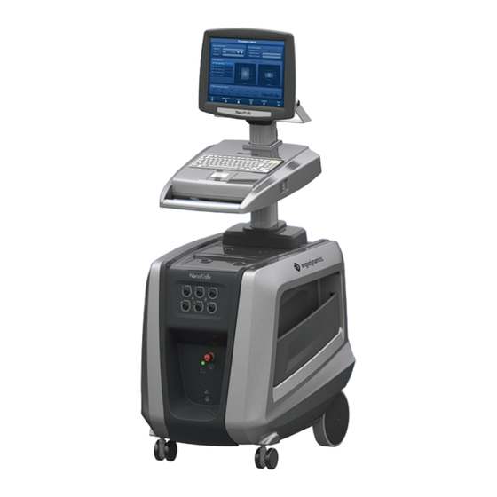
The NanoKnife Generator in Figure 3.1.1 includes the following: 1. Touchscreen LCD Display 3. Power Unit and Power Cord 2. Console and Keyboard 4. Double Pedal Footswitch Figure 3.1.1: NanoKnife Generator – Main Components 16795933-21 REVC - English NanoKnife System User Manual Version 3.0... -
Page 18: Nanoknife Generator Description
User Manual Front Wheel Brakes Each front wheel is supplied with a lever to stop the wheel; a lowered lever stops the wheel, a raised lever frees the wheel 16795933-21 REVC - English NanoKnife System User Manual Version 3.0... -
Page 19: Nanoknife Generator - Lower Front Components
Red STOP button must be released to proceed with procedure. Pedal Connector, Connection site for the Double Pedal Footswitch identified by the symbol 16795933-21 REVC - English NanoKnife System User Manual Version 3.0... -
Page 20: Nanoknife Generator Power Unit - Lower Back Components
Connects the mains power supply cord External Sync Connector Connects a cardiac gating device, e.g., QRS detection Data Plate Indicates the unit name, model, serial number, manufacturer, power supply specifications, and power fuse specifications 16795933-21 REVC - English NanoKnife System User Manual Version 3.0... -
Page 21: Nanoknife Generator Back Handle
Double Pedal Footswitch Power Cord Optional Electrodes (Purchased separately) NOTE: The Double Pedal Footswitch is an essential part of the NanoKnife System. It is graded IPX-8. It is required to use only genuine parts supplied by the NanoKnife’s manufacturer or authorized distributor. -
Page 22: Console Components
USB Ports to connect USB Storage Devices Electrode Probe Components Electrode Probes are available from AngioDynamics for use with the NanoKnife Generator. Single Electrode Probes are available in 15 cm and 25 cm lengths. A minimum of two probes is required for a procedure. -
Page 23: Section 4: Installation And Start-Up
Checking Device Status • Checking Connections • Testing Charge A status bar displays the progress of the start-up self test, Figure 4.2.1 and Figure 4.2.2. Figure 4.2.1: Start-Up Screen in Progress 16795933-21 REVC - English NanoKnife System User Manual Version 3.0... - Page 24 Refer to Section 12.3 for a complete list of start-up self test error messages. If all self-tests are successful, the Procedure Setup screen will appear on the Touchscreen LCD Display (see Figure 6.1.1). If the generator repeatedly fails the self test, call AngioDynamics Hardware Service.
-
Page 25: Section 5: System Operation
12. OPTIONAL: Make a surgical incision (e.g., for NanoKnife procedures performed via laparotomy i.e., open surgery). 13. OPTIONAL: Perform other intended procedures on patient (e.g., metal stent removal, biopsy, lysis of adhesions, etc.). 16795933-21 REVC - English NanoKnife System User Manual Version 3.0... -
Page 26: Procedure Planning
26. Uniquely number each Single Electrode Probe (1 thru 6) at both ends of the Single Electrode Probe cabling using pre-numbered tags supplied with probes or a sterile marker and Steri-Strip. Figure 5.1.4: Single Electrode Probes Uniquely Numbered 16795933-21 REVC - English NanoKnife System User Manual Version 3.0... -
Page 27: Probe Placement
39. Optional: Use clinical judgement to either accept or modify the default pulse parameters. Refer to Section 5.3 Procedure Parameter Settings for more information. 16795933-21 REVC - English NanoKnife System User Manual Version 3.0... -
Page 28: Pulse Generation
56. Single Electrode Probes are sharp devices. Used or unused devices and should be disposed of in accordance with hospital, administrative and/or local government policy for such items. 16795933-21 REVC - English NanoKnife System User Manual Version 3.0... -
Page 29: Equipment Shut-Down, Cleaning, And Storage
Procedural Guidelines and Recommendations • The NanoKnife System requires deep muscle blockade and general anesthesia (0/4 twitches on the Train of Four Test). • ASA guidelines require a defibrillator be readily available for general anesthesia (defibrillator pads are recommended). -
Page 30: Procedure Parameter Settings
Maximum system setting 100 pulses Typical range used for this setting 70 - 90 pulses Typical number of total pulses per probe pair (after multiple rounds) 140 – 270 pulses 16795933-21 REVC - English NanoKnife System User Manual Version 3.0... -
Page 31: Table Of Buttons
Settings button on all screens opens the Settings dialog box, which displays available language and Pulse Delivery Mode settings. Next button on the Procedure Setup and Procedure Planning screens takes you to the next screen. 16795933-21 REVC - English NanoKnife System User Manual Version 3.0... - Page 32 ‘Folders to be saved’ box. Remove Folder button on the Export dialog box allows the User to remove the selected folder of procedure data from the ‘Folders to be saved’ box. 16795933-21 REVC - English NanoKnife System User Manual Version 3.0...
- Page 33 Reverse All Pairs button on the Polarity Tab re-assigns the polarity of all probe pairs. Reverse Polarity Button located on the Modify Probe Pair popup reverses the polarity of the Active Probe Pair. 16795933-21 REVC - English NanoKnife System User Manual Version 3.0...
- Page 34 User to CLEAR the initial current, max current, current change, and pulses delivered values and CLEAR the results graph. NOTE: a warning dialog box will appear to confirm Users intended selection. 16795933-21 REVC - English NanoKnife System User Manual Version 3.0...
-
Page 35: Table Of Status Symbols
NOTE: Press the Right (PULSE) Footswitch Pedal before the countdown has completed. If the Right (PULSE) Footswitch Pedal is not pressed within the 10-second countdown, the NanoKnife Generator will disarm. 16795933-21 REVC - English NanoKnife System User Manual Version 3.0... - Page 36 “ECG Noisy” if ECG synchronization is selected and signal is too fast. “ECG Lost” if ECG synchronization is selected and signal is too slow or not present. 16795933-21 REVC - English NanoKnife System User Manual Version 3.0...
-
Page 37: Section 6: Procedure Setup
The Case Information panel allows the User to enter procedure information: • Procedure Date – Automatically set. • Physician Name – Optional, text entered using keyboard. • Ablation Location – Optional, text entered using keyboard. 16795933-21 REVC - English NanoKnife System User Manual Version 3.0... -
Page 38: Patient Information
The Age, Gender, and Diagnosis are not required to be entered. Enter patient’s ID into the Patient ID text box using the keyboard. The Patient ID may contain numbers and/or letters. Figure 6.2.1: Patient Information Panel 16795933-21 REVC - English NanoKnife System User Manual Version 3.0... - Page 39 Table 6.2.1: Gender Switch Buttons Gender Meaning Default – no gender selected Male selected Female selected To enter patient’s diagnosis, click the Diagnosis text box and enter patient’s diagnosis using the keyboard. 16795933-21 REVC - English NanoKnife System User Manual Version 3.0...
-
Page 40: Case Information
Figure 6.4.1: Probe Selection The User should select a number of probes based on the targeted ablation area size and shape. All ablation procedures using the NanoKnife System should be based on imaging measurements and using clinical judgment. The Probe Selection panel includes a list of the number of probes: Two Probe Array, Three Probe Array, Four Probe Array, Five Probe Array, and Six Probe Array. - Page 41 The available probes arrays to choose from in the Probe Selection panel are listed in Figure 6.4.2. Two Probe Array Three Probe Array Four Probe Array 16795933-21 REVC - English NanoKnife System User Manual Version 3.0...
-
Page 42: Probe Connection Status
Probe Connectors located on the front panel of the NanoKnife Generator, Figure 6.5.1. The NanoKnife Software checks the expiration and authenticity of each probe connected. Figure 6.5.1: Probe Connection Status 16795933-21 REVC - English NanoKnife System User Manual Version 3.0... - Page 43 2. The probes connected to the NanoKnife Generator are not expired or invalid. 3. The probes are connected in sequential order (e.g. four probes are connected to probe connector 1, 2, 3, and 4). 16795933-21 REVC - English NanoKnife System User Manual Version 3.0...
- Page 44 The User must meet the probe connection requirements before advancing to the Pulse Generation screen. Return to the Procedure Setup screen and check probe connection status. Figure 6.5.4: Check Probe Connection Status Popup 16795933-21 REVC - English NanoKnife System User Manual Version 3.0...
- Page 45 NOTE: A probe may be used with a different NanoKnife Generator; however, the eight- hour working time will not change. The probe expires eight hours after the probe has been connected and recognized by the first NanoKnife Generator. 16795933-21 REVC - English NanoKnife System User Manual Version 3.0...
-
Page 46: Pulse Delivery Mode Setting
Settings dialog box. Click the 90 Pulses Per Minute radio button. A warning popup will appear, Figure 6.6.3. Figure 6.6.3: Pulse Timing Warning Popup 16795933-21 REVC - English NanoKnife System User Manual Version 3.0... -
Page 47: How To Change Pulse Delivery Mode To Ecg Synchronized
The light blue text box located on the bottom of the dialog box is where new case notes are entered. 16795933-21 REVC - English NanoKnife System User Manual Version 3.0... -
Page 48: How To Enter Case Notes
Figure 6.7.3: Case Notes Dialog Box – New Case Note Click the button to record the note and close the Case Notes dialog box. Clicking the button would discard the new note and close the Case Notes dialog box. 16795933-21 REVC - English NanoKnife System User Manual Version 3.0... -
Page 49: Proceed To Next Screen
Figure 6.7.4: Case Notes Dialog Box – Time Stamped Notes Proceed to Next Screen After completing the Information sections, click the Next button to proceed to the Procedure Planning screen. Figure 6.8.1: Navigation Bar – Next Button 16795933-21 REVC - English NanoKnife System User Manual Version 3.0... -
Page 50: Section 7: Procedure Planning
Polarity – Easily adjust polarity of a probe pair or all probe pairs. • Options – Turn on or off Probe Placement Grid features. Detailed instructions on how to utilize the Procedure Planning screen are described in the following subsections. 16795933-21 REVC - English NanoKnife System User Manual Version 3.0... -
Page 51: Probe Placement Grid
Probe Connection Status, Table 7.2.1. Table 7.2.1: Probe Placement Grid – Grid Icons Grid Icon Meaning Probe not connected or not recognized Probe connected and valid Probe connected and expired or invalid 16795933-21 REVC - English NanoKnife System User Manual Version 3.0... - Page 52 Figure 7.2.3: Probe Placement Grid – Selecting and Moving Multiple Grid Icons NOTE: Clicking the Restore Default Settings button will return the Probe Placement Grid and Pulse Parameters Table to default values. 16795933-21 REVC - English NanoKnife System User Manual Version 3.0...
-
Page 53: Targeted Ablation Area Settings
The Procedure Planning Cube on the left of the Lesion Zone settings is a graphical representation of four probes bracketing a lesion to help the User determine the targeted lesion and probe placement orientation. 16795933-21 REVC - English NanoKnife System User Manual Version 3.0... - Page 54 Figure 7.3.4: Modified Lesion Zone Settings The Margin is the distance between the Lesion Zone and the Target Zone. ATTENTION: Modification of the Margin setting should be based on clinical determination by the treating physician. 16795933-21 REVC - English NanoKnife System User Manual Version 3.0...
-
Page 55: Target Zone Rotation Handle
The Targeted Ablation Area will rotate about the center point of the Lesion Zone in the same direction as the User’s click and drag motion, Figure 7.4.1. Figure 7.4.1: Procedure Zone Rotator – Rotation Mode 16795933-21 REVC - English NanoKnife System User Manual Version 3.0... -
Page 56: Pulse Parameters Table
NOTE: The Active Probe Pairs included in the Pulse Parameters Table are listed in sequential order. Active Probe Pairs will be reordered from highest to lowest voltage on the Pulse Generation screen. 16795933-21 REVC - English NanoKnife System User Manual Version 3.0... - Page 57 V/cm calculate Voltage of the Active Probe Pair with units in Volts/cm. Distance between the positive and negative probes of an Active Probe Distance Pair with units in centimeters (cm). 16795933-21 REVC - English NanoKnife System User Manual Version 3.0...
-
Page 58: Pulse Parameter Constraints
0 cm 11.3 cm 0.1 cm (Probe Pair (with probe (with probe Distance) placement grid placement grid enabled) enabled) 0.1cm 5.0cm (with probe (with probe placement grid placement grid disabled) disabled) 16795933-21 REVC - English NanoKnife System User Manual Version 3.0... -
Page 59: How To Modify Pulse Parameters
The orange cell backfill indicates the parameter is 3000 set at the maximum or minimum value. NOTE: Clicking the Restore Default Settings button will return the Probe Placement Grid and Pulse Parameters Table to default values. 16795933-21 REVC - English NanoKnife System User Manual Version 3.0... -
Page 60: How To Modify Pulse Parameters For All Active Probe Pairs
Clicking the button will discard the values and close the popup. The Pulse Parameters Table will update to reflect the change. 16795933-21 REVC - English NanoKnife System User Manual Version 3.0... - Page 61 Parameters Table a warning popup will appear, Figure 7.5.6. Figure 7.5.6: Attention Popup – Identical Probe Pair Click the button to close the Attention popup. The P+ and P- values will return back to the original values. 16795933-21 REVC - English NanoKnife System User Manual Version 3.0...
-
Page 62: How To Reverse Polarity Of Active Probe Pairs
Probe Placement Grid and enter probe pair distances for Active Probe Pairs, click the cell in the Distance column that contains the value to display an Attention popup Figure 7.5.8. Figure 7.5.8: Attention Popup – Disable Probe Placement Grid 16795933-21 REVC - English NanoKnife System User Manual Version 3.0... - Page 63 Figure 7.5.10: Probe Placement Grid – Disabled NOTE: Clicking the Restore Default Settings button will re-enable the Probe Placement Grid and return the Probe Placement Grid and Pulse Parameters Table to default values. 16795933-21 REVC - English NanoKnife System User Manual Version 3.0...
-
Page 64: How To Re-Enable The Probe Placement Grid
Figure 7.6.1. Figure 7.6.1: Background Color Change 16795933-21 REVC - English NanoKnife System User Manual Version 3.0... -
Page 65: How To Add Probe Pairs To The Pulse Parameters Table
Figure 7.6.3. Figure 7.6.3: Add Row to Pulse Parameters Table NOTE: Clicking the Restore Default Settings button will return the Probe Placement Grid and Pulse Parameters Table to default values. 16795933-21 REVC - English NanoKnife System User Manual Version 3.0... -
Page 66: Distance Solver
Distance Solver dialog box. Input the desired distances between probes into the dark grey boxes of the Distance Solver dialog box, Figure 7.7.2. Figure 7.7.2: Pulse Parameters Table & Adjuster 16795933-21 REVC - English NanoKnife System User Manual Version 3.0... - Page 67 Distance Solver dialog box and display the Distance Solver Results dialog box. NOTE: The Distance Solver Status popup may display while a solution is calculated, Figure 7.7.4. Figure 7.7.4: Distance Solver Status popup 16795933-21 REVC - English NanoKnife System User Manual Version 3.0...
-
Page 68: Quick Adjust Tab
The Quick Adjust tab displays a set of controls that allows the User to quickly add or remove probe pairs, modify pulse parameters for all Active Probe Pairs, and enter in Probe Exposure settings, Figure 7.8.1. Figure 7.8.1: Quick Adjust Tab 16795933-21 REVC - English NanoKnife System User Manual Version 3.0... -
Page 69: How To Quickly Add Or Remove Probe Pairs
NOTE: Not all parameters options are displayed. Use the / buttons to modify the parameter and access pulse parameters above or below what is displayed. A button that turns midnight blue indicates the parameter is set to either the minimum or maximum value. 16795933-21 REVC - English NanoKnife System User Manual Version 3.0... -
Page 70: How To Quickly Modify Voltage Setting For All Probe Pairs
The Help Text box provides additional information. To open the help screen select the ? symbol in the upper right of the Procedure Planning Screen. Figure 7.8.3: Quick Adjust Parameters Tab – Help Popup 16795933-21 REVC - English NanoKnife System User Manual Version 3.0... -
Page 71: Polarity Tab
+ or – buttons to re-assign the polarity of a probe pair. 7.9.2 How to Re-Assign Polarity of All Probe Pairs Click the Reverse All Pairs button to re-assign the polarity of all probe pairs. 16795933-21 REVC - English NanoKnife System User Manual Version 3.0... -
Page 72: Options Tab
Hide (OFF) or display (ON) the dotted and arrowed lines between active probe pairs. Minor Grid Lines Hide (OFF) or display (ON) the millimeter grid lines. Major Grid Lines Hide (OFF) or display (ON) the centimeter grid lines. 16795933-21 REVC - English NanoKnife System User Manual Version 3.0... -
Page 73: How To Modify Probe Placement Grid Options
Probe Placement Grid and Pulse Parameters Table to default values; including the Targeted Ablation Area Settings, Grid Icon locations, Probe Polarity, and Probe Placement Grid Options. Figure 7.11.1: Restore Default Settings Popup 16795933-21 REVC - English NanoKnife System User Manual Version 3.0... -
Page 74: Proceed To Next Screen
Attempting to proceed to the Pulse Generation screen without the correct number of probes connected to the generator will bring up an Attention popup, Figure 7.12.2. Figure 7.12.2: Check Probe Connection Status Popup 16795933-21 REVC - English NanoKnife System User Manual Version 3.0... -
Page 75: Section 8: Pulse Generation
Synchronization status indicator and message window. The message window displays helpful information during and after pulse delivery. Detailed instructions on how to utilize the Pulse Generation screen are described in the following subsections. 16795933-21 REVC - English NanoKnife System User Manual Version 3.0... -
Page 76: Pulse Generation Table
The status is 100% if all intended pulses are delivered. If pulse delivery is stopped or the User skips the remaining pulses for a probe pair, the Status indicates only the successfully completed pulse trains. 16795933-21 REVC - English NanoKnife System User Manual Version 3.0... -
Page 77: How To Modify Pulse Parameters
The yellow cell backfill indicates a pulse parameter is 1200 either above or below the default value. The orange cell backfill indicates the parameter is set at 3000 the maximum or minimum value. 16795933-21 REVC - English NanoKnife System User Manual Version 3.0... -
Page 78: How To Modify Pulse Parameters For All Probe Pairs
Clicking the button will discard the values and close the popup. The Pulse Generation Table will update to reflect the change. 16795933-21 REVC - English NanoKnife System User Manual Version 3.0... -
Page 79: How To Deactivate Probe Pairs
Clicking the button will discard the changes and close the popup. The Pulse Generation Table will update to reflect the change, Figure 8.2.7. Figure 8.2.7: Deactivated Probe Pair 16795933-21 REVC - English NanoKnife System User Manual Version 3.0... -
Page 80: How To Activate Probe Pairs
Figure 8.2.9. Max Current Max Current Current Change Current Change Initial Current Initial Current Figure 8.2.9: Initial, Max, and Change in Current 16795933-21 REVC - English NanoKnife System User Manual Version 3.0... -
Page 81: How To Evaluate Pulses Delivered And Status
Figure 8.2.11. Figure 8.2.11: Status Bar during Pulse Delivery The Status Bar is synchronized to the Electrical Results Chart. The Status Bar will update after each pulse is delivered. 16795933-21 REVC - English NanoKnife System User Manual Version 3.0... -
Page 82: Probe Pair Status Grid
The Electrical Results Charts include vertical grid lines which represent transitions between each probe pairs listed within the Pulse Generation Table, Figure 8.4.1. Figure 8.4.1: Voltage Results Graphs with Vertical Grid Lines 16795933-21 REVC - English NanoKnife System User Manual Version 3.0... -
Page 83: How To Toggle Between Electrical Results Charts
A synchronized Status Bar positioned below the Electrical Results Chart indicates the overall pulse delivery progress, Figure 8.4.3. Figure 8.4.3: Current Results Chart during Pulse Delivery 16795933-21 REVC - English NanoKnife System User Manual Version 3.0... -
Page 84: Electrical Results Chart After Pulse Delivery
Figure 8.4.6: Electrical Results Chart – One Pulse Train The User may zoom out to view the electrical measurements for all probe pairs by clicking anywhere within the chart area. 16795933-21 REVC - English NanoKnife System User Manual Version 3.0... -
Page 85: Voltage Gauge And Charge Options
The various Voltage Gauge states are shown in Table 8.5.1. Table 8.5.1: Voltage Gauge States Discharged Conductivity Test Pulse Delivery NOTE: The capacitors will discharge if the NanoKnife System is left idle on the Pulse Generation Screen for 5 minutes. 8.5.1 How to Discharge Capacitors Click the button to discharge the capacitors. -
Page 86: Audible Indications During Pulse Delivery
The Pulse Delivery Control panel is where the User can stop pulse delivery, skip a probe pair during pulse delivery, and charge or discharge the capacitors, Figure 8.7.1. Figure 8.7.1: Pulse Delivery Control Panel 16795933-21 REVC - English NanoKnife System User Manual Version 3.0... - Page 87 “ECG Noisy” if ECG synchronization is selected and signal is too fast (i.e. above 120 bpm). “ECG Lost” if ECG synchronization is selected and signal is too slow or not present. 16795933-21 REVC - English NanoKnife System User Manual Version 3.0...
-
Page 88: How To Start The Conductivity Test
Panel will display the Double Pedal Footswitch icon with the right pedal illuminated green with a 10-second countdown, Figure 8.7.4. Figure 8.7.4: Double Pedal Footswitch Icon - Right Pedal Illuminated 16795933-21 REVC - English NanoKnife System User Manual Version 3.0... - Page 89 The Status Bar will indicate the progress through the conductivity test and percentage complete. After the Conductivity Test is complete, the message window will display text as shown below in Figure 8.7.7. Figure 8.7.7: Message Window while Conductivity Test is Complete 16795933-21 REVC - English NanoKnife System User Manual Version 3.0...
-
Page 90: High Current Detected During The Conductivity Test
45 Amps, Figure 8.7.10. Predict. Current Current Current Change 100.0 100.0 100.0 Figure 8.7.10: Pulse Generation Table – Conductivity Test – High Current Detected 16795933-21 REVC - English NanoKnife System User Manual Version 3.0... -
Page 91: Low Current Detected During The Conductivity Test
ATTENTION: Low current measurements may be expected based on the impedance of the targeted tissue. Use clinical judgement to ignore the conductivity results and proceed. 16795933-21 REVC - English NanoKnife System User Manual Version 3.0... -
Page 92: How To Modify Pulse Parameters After The Conductivity Test
Test. When the capacitors reach full charge, the Pulse Delivery Control Panel will display the Double Pedal Footswitch icon with the left pedal illuminated green, Figure 8.7.13. Figure 8.7.13: Double Pedal Footswitch Icon - Left Pedal Illuminated 16795933-21 REVC - English NanoKnife System User Manual Version 3.0... - Page 93 Generator Probe Connector, and the distances between the probes have been accurately entered into the Probe Placement Grid. Refer to Section 12 for additional troubleshooting information. 16795933-21 REVC - English NanoKnife System User Manual Version 3.0...
- Page 94 Pulse Delivery Control panel and their meaning. Pulse delivery will stop until the ECG Synchronization signal is restored. Refer to Section 10: for more information on ECG Synchronized Pulse Delivery. 16795933-21 REVC - English NanoKnife System User Manual Version 3.0...
-
Page 95: How To Stop Pulse Delivery
Clicking the button will restart pulse delivery. Clicking the button will close the popup and not charge the capacitors. Refer to Section 8.7.8 for information on restarting pulse delivery. 16795933-21 REVC - English NanoKnife System User Manual Version 3.0... -
Page 96: How To Reset Pulse Delivery Mid Pulse Delivery
At any point during pulse delivery, the User can skip the remaining pulses to be delivered for the Active Probe Pair by pressing the Skip Probe Pair button, Figure 8.7.25. Figure 8.7.25: Pulse Delivery Control Panel – Skip Probe Pair Button 16795933-21 REVC - English NanoKnife System User Manual Version 3.0... -
Page 97: Low Current Conditions During Pulse Delivery
Figure 8.7.29. Refer to Section 12, Troubleshooting for additional information regarding low current detected during pulse delivery. Figure 8.7.29: Message Window - Low Current Detected during Pulse Delivery 16795933-21 REVC - English NanoKnife System User Manual Version 3.0... -
Page 98: High Current Conditions During Pulse Delivery
Generator will attempt to deliver another pulse train at the same pulse parameters. The Generator attempts to deliver all intended pulses unless the Stop Pulse Delivery button is pressed. 16795933-21 REVC - English NanoKnife System User Manual Version 3.0... - Page 99 CAUTION: Using shorter probe exposures will significantly reduce current draw during pulse delivery. To minimize the occurrence of High Current and Over Current Conditions, use shorter probe exposures. Refer to Section 8.7.7 for instruction on resuming pulse delivery. 16795933-21 REVC - English NanoKnife System User Manual Version 3.0...
-
Page 100: How To Deliver Additional Pulses
Note: Anytime the pulse data is reset, the conductivity test must be repeated before proceeding to pulse delivery 16795933-21 REVC - English NanoKnife System User Manual Version 3.0... -
Page 101: How To Reset Pulse Delivery For An Overlapping Ablation
Generator internally disconnects the energy load and automatically discharges the energy accumulated on the capacitors. The Hardware / Communication Failure popup displays, Figure 8.7.35. Figure 8.7.35: Hardware / Communication Failure Popup 16795933-21 REVC - English NanoKnife System User Manual Version 3.0... -
Page 102: Storage Of Pulse Parameters And Electrical Results Charts
“HH.MM-SS” in 24 hours format. The PDF file is referred to as the NanoKnife Procedure Report, Figure 8.7.36. Figure 8.7.36: NanoKnife Procedure Report PDF 16795933-21 REVC - English NanoKnife System User Manual Version 3.0... - Page 103 NOTE: An XML file can be opened in commercial applications like *Microsoft Excel 2003 or newer, Open Office spreadsheet, Notepad, etc. Refer to Section 9.1.1 for more information on how to export procedure files. 16795933-21 REVC - English NanoKnife System User Manual Version 3.0...
-
Page 104: Section 9: End Of Procedure
Each folder contains a set of procedure files for all procedures performed on that date. 2. Click the Add Folder button to add the selected folder to the ‘Folders to be saved’ text box, Figure 9.1.3. 16795933-21 REVC - English NanoKnife System User Manual Version 3.0... - Page 105 Figure 9.1.4: Procedure Files Saved Popup 5. Remove the USB storage device from the NanoKnife Generator. NOTE: Exporting procedure files to a USB storage device does not remove the files from the NanoKnife Generator. 16795933-21 REVC - English NanoKnife System User Manual Version 3.0...
-
Page 106: Disconnect Electrode Probes
Shut Down the NanoKnife Generator Click the Exit button located on either the navigation bar of the Procedure Setup or Pulse Generation screens, Figure 9.4.1. Figure 9.4.1: Navigation Bar – Exit Button 16795933-21 REVC - English NanoKnife System User Manual Version 3.0... - Page 107 OFF position. ATTENTION: Turning the main power switch to the OFF location before hearing the audible beep may damage the NanoKnife Generator. 16795933-21 REVC - English NanoKnife System User Manual Version 3.0...
-
Page 108: Section 10: Ecg Synchronization
The Generator starts in the ECG Synchronous mode (default setting). When working in this mode, the Generator must be connected to an external R-wave detector. 10.2 External R-Wave Detector / Cardiac Gating Device The external R-wave detector must be an IVY Model 7600 device, AngioDynamics part number 3303-30-15 •... -
Page 109: Ecg Lost
If the ECG signal stays within the acceptable range during the Conductivity Test then the ECG Synchronization status indicator will display as shown in Figure 10.5.1. Figure 10.5.1: ECG Synchronized during the Conductivity Test 16795933-21 REVC - English NanoKnife System User Manual Version 3.0... -
Page 110: Ecg Lost
Conductivity Test Voltage. The Generator is ready to restart the Conductivity Test. Refer to Section 8.7.1 for more instruction on Starting the Conductivity Test. 16795933-21 REVC - English NanoKnife System User Manual Version 3.0... -
Page 111: During Pulse Delivery
Figure 10.6.3: ECG Lost during Pulse Delivery - Discharged After the ECG Signal has been restored, the Charge button will appear as shown in Figure 10.6.4. Figure 10.6.4: ECG Signal Restored during Pulse Delivery 16795933-21 REVC - English NanoKnife System User Manual Version 3.0... -
Page 112: Ecg Noisy
After the ECG Signal has been restored, the Charge button will appear as shown in Figure 10.6.8. Figure 10.6.8: ECG Signal Restored during Pulse Delivery To resume pulse delivery, click the button to display the charge options popup as shown below in Figure 10.6.9. 16795933-21 REVC - English NanoKnife System User Manual Version 3.0... - Page 113 Refer to Section 8.7.7 for more instruction on Resuming Pulse Delivery. 16795933-21 REVC - English NanoKnife System User Manual Version 3.0...
-
Page 114: Section 11: Electrode Probes
NanoKnife Single Electrode Probes can be used for any one procedure. Probes may be re-positioned after successful pulse delivery to cover a larger area utilizing an overlapping and/ or pullback ablation technique. 16795933-21 REVC - English NanoKnife System User Manual Version 3.0... - Page 115 4.0 cm Figure 11.1.2: NanoKnife Single Electrode Probe Configuration Examples The NanoKnife Generator is only to be used with Electrode Probes supplied by AngioDynamics, Inc. that are specified for use with the NanoKnife Generator, with most currently available software.
-
Page 116: Section 12: Troubleshooting
Use the touchscreen in place of the touchpad. User can temporarily use a mouse connected to the USB port, to complete procedure. In general, it is not recommended to use a mouse. Call AngioDynamics Hardware Service. Malfunction: Cannot arm or activate conductivity test or pulse delivery. Possible Reasons... - Page 117 Probes connected to wrong Stop pulse delivery. Verify probes are connected to the Electrode Probe Connectors. proper Electrode Probe Connectors. Resume pulse delivery and complete any undelivered pulses. 16795933-21 REVC - English NanoKnife System User Manual Version 3.0...
- Page 118 5mm and Repeat the Conductivity Test. Probe has bent cable connector Inspect each cable connector for a bent pin. Replace pin. defective probe. Repeat the Conductivity Test. 16795933-21 REVC - English NanoKnife System User Manual Version 3.0...
-
Page 119: Error Messages
NanoKnife Software and the NanoKnife Generator Controller. The NanoKnife Generator start- Call AngioDynamics Hardware Service. up self test has failed because of a damaged or faulty component. 16795933-21 REVC - English NanoKnife System User Manual Version 3.0... - Page 120 ATTENTION: Using a pulse length below 70 µsec may targeted tissue. result in an incomplete ablation. Probes connected to wrong Verify probes are connected to the proper Electrode Electrode Probe Connectors. Probe Connectors. 16795933-21 REVC - English NanoKnife System User Manual Version 3.0...
- Page 121 R-wave and T-Wave. Cardiac gating device lead pair Select a different ECG lead pair. Refer to Section 5.1.2 has high amplitude P-wave. for instruction on selecting an appropriate lead pair. 16795933-21 REVC - English NanoKnife System User Manual Version 3.0...
- Page 122 Click the Charge button. The NanoKnife Generator capacitors. should charge the capacitors. If the system is not able to charge or discharge the capacitors, call AngioDynamics Hardware Service. 16795933-21 REVC - English NanoKnife System User Manual Version 3.0...
- Page 123 Low current warnings may be expected based on the conductivity or high impedance. impedance of the targeted tissue. Use clinical judgement to ignore the low current warnings and continue pulse delivery. 16795933-21 REVC - English NanoKnife System User Manual Version 3.0...
- Page 124 Probes connected to wrong Stop pulse delivery. Verify probes are connected to the Electrode Probe Connectors. proper Electrode Probe Connectors. Resume pulse delivery and complete any undelivered pulses. 16795933-21 REVC - English NanoKnife System User Manual Version 3.0...
-
Page 125: Section 13: Maintenance & Service
13.1 Overview This section describes the recommended periodical checks and preventive maintenance that the User should complete to ensure that the NanoKnife System will satisfactorily perform its intended function. There are no User-serviceable parts inside the Generator. The warranty will be voided if the unit is opened and/or the warranty seal is broken. -
Page 126: Replacing Main Fuses
5. Replace the two fuses contained in the fuse-holder with new fuses as indicated on the Device Plate Label. 6. Place the fuse-holder back into the Power Supply Group and close the cover. 7. Reconnect the main power cord. 16795933-21 REVC - English NanoKnife System User Manual Version 3.0... -
Page 127: Section 14: Technical Data
-20° C to +60° C Relative Humidity: 10% to 90% Atmospheric Pressure: 70 to 106 Kpa 14.5 Classifications 14.5.1 EN 60601-1 Classification Protection Against Electric Shock: Class I CISPR 11 Class A (EMC) 16795933-21 REVC - English NanoKnife System User Manual Version 3.0... -
Page 128: Protection Against Electric Shock
*Number of pulses for each pair of electrodes. **Between recharges 14.8 Essential Performance The System must deliver energy within stated voltage tolerance of ± 15% of the user requested pulse voltage. 16795933-21 REVC - English NanoKnife System User Manual Version 3.0... -
Page 129: Radio Frequency Identification
128-bit AES. The NanoKnife System may take up to 10 seconds to process. Should there be a communication issue and the system is unable to read the tag, or is not valid or recognized, the system will inform the user of the probe status, and will not allow the user to progress to the next step. -
Page 130: Intended User Profile
• Mobility: The NanoKnife System may be moved between rooms within a hospital. It is to remain within the hospital, but may be transported between rooms and wards as needed for varying procedure approaches and storage. -
Page 131: Section 15: Warranty And Electromagnetic Compatibility
Warning: The NanoKnife Generator should not be used adjacent to or stacked with other equipment not designed to be used with the NanoKnife System and that if adjacent or stacked use in necessary, the NanoKnife Generator should be observed to verify normal operation in the configuration in which it will be used. - Page 132 NOTE 1: At 80 MHz and 800 MHz, the separation distance for the higher frequency range applies. NOTE 2: These guidelines may not apply in all situations. Electromagnetic propagation is affected by absorption and reflection from structures, objects and people. 16795933-21 REVC - English NanoKnife System User Manual Version 3.0...
- Page 133 Test Specifications on NanoKnife System for Immunity to RF Wireless Communication Carriers Test Immunity Band(a) Distance Frequency Service(a) Modulation(b) Power Test Level (MHz) (MHz) (V/m) Pulse(b) 380-390 TETRA Modulation (18 Hz) FM(c) GMRS 460(c) 430-470 ± 5KHz deviation FRS 460...
- Page 134 61000-4-8 of a typical location in a typical commercial or hospital environment. NOTE UT is the AC mains voltage prior to application of the test level. 16795933-21 REVC - English NanoKnife System User Manual Version 3.0...
- Page 135 NanoKnife Generator. B: Over the frequency range 150 kHz to 800 MHz, field strengths should be less than 3 V/m. 16795933-21 REVC - English NanoKnife System User Manual Version 3.0...
- Page 136 Harmonic Class A network that supplies buildings used for domestic purposes. emissions IEC 61000-3-2 Voltage Not applicable fluctuations / flicker emissions IEC 61000-3-3 16795933-21 REVC - English NanoKnife System User Manual Version 3.0...
-
Page 137: Section 16: Symbols Glossary
Upper limit of 5.3.6 to which the medical device can be safely temperature exposed. Indicates the temperature limits to which the 5.3.7 Temperature limit medical device can be safely exposed. 16795933-21 REVC - English NanoKnife System User Manual Version 3.0... - Page 138 0434B the symbol is placed. Caution, risk of To identify equipment that has risk of electric 6042 electric shock shock. Follow instructions for Refer to instruction manual. ifu.angiodynamics.com 16795933-21 REVC - English NanoKnife System User Manual Version 3.0...
- Page 139 EU 2017/745 Medical Device Regulations published 5 May 2017 j. ISO 780 Distribution packaging - Graphical symbols for handling and storage of packages k. EN ISO 14021 Environmental labels and declarations. Self-declared environmental claims (Type II environmental labeling) 16795933-21 REVC - English NanoKnife System User Manual Version 3.0...
- Page 140 © 2024 AngioDynamics, Inc. or its affiliates. All rights reserved.
Need help?
Do you have a question about the NanoKnife System and is the answer not in the manual?
Questions and answers