Table of Contents
Advertisement
Quick Links
Advertisement
Table of Contents

Related Manuals for AngioDynamics NanoKnife


Summary of Contents for AngioDynamics NanoKnife
- Page 2 User Manual Copyright © 2009-2010 AngioDynamics. All rights reserved. AngioDynamics is a registered trademark and NanoKnife is a registered trademark of AngioDynamics with patents pending in the United States and foreign countries. This documentation contains proprietary information of AngioDynamics. No part of this manual may be reproduced or transmitted in any form or by any means, electronic or mechanical, for any purpose, without the written permission of AngioDynamics.
-
Page 3: Table Of Contents
ONTENTS ECTION NTRODUCTION 1.1 Overview ................. 7 1.2 Symbols .................. 8 1.2.1 Standard Symbols ..............8 1.2.2 Specific Part Symbols ............9 1.2.3 Icons .................. 10 ECTION AFETY NSTRUCTIONS ... -
Page 4: Ection
4.2 Generator Start-Up and Warm-Up ........28 ECTION PERATION 5.1 Overview ................31 5.1.1 Table of Buttons ..............32 5.1.2 Information Screen ............. 34 5.1.3 Probe Selection Screen ............. 40 5.1.4 ... - Page 5 10.4.1 Operating Conditions ............88 10.5 Classifications ..............88 10.6 Use Conditions ..............89 10.7 Technical Specifications ............. 89 10.8 Radio Frequency Identification ......... 90 ECTION ARRANTY AND LECTROMAGNETIC OMPATIBILITY 11.1 ...
-
Page 6: Version 2.2.0
160-104694 Rev 01 Version 2.2.0... -
Page 7: Introduction
NanoKnife System is a Footswitch for the Generator. The footswitch connects to the Generator and also operates outside the sterile field. The last component of the NanoKnife System is the single-use, disposable Electrode. The electrodes operate in the sterile field and are packaged and shipped sterile. The NanoKnife System has six probe outputs, which allow Users to connect up to six electrodes at one time. -
Page 8: Symbols
Symbols As with any custom software, the NanoKnife System uses specific symbols and icons. The following is a list of the standard symbols and icons used in this manual. All of the symbols used on the NanoKnife System are in conformity with CEI 62-5 Directives. -
Page 9: Specific Part Symbols
Symbol Meaning Location Defibrillator Proof (Body protected) Printed on the front of the Generator in between the probe connectors Federal Communications Commission Printed on the data plate European Conformity Marking with notified body identification number ... -
Page 10: Icons
1.2.3 Icons Icons are image files that are meant to resemble the task you wish to complete and will launch that task when "clicked" or are graphical User interface elements that provide options. Icon Function Description Generator User login icon ... -
Page 11: Afety Nstructions
Federal or USA law restricts the use of the system by or on the order of a physician. Intended Use: The NanoKnife System with its six outputs is indicated for the surgical ablation of soft tissue. 160-104694 Rev 01... -
Page 12: Safety Features Of The Generator
Safety Features of the Generator The Generator incorporates the following safety features to assist the User in delivering a safe application: Output Current Restriction When the Generator senses that the current between the electrodes exceeds the operating parameters, the pulses are aborted. This safety feature protects against applying output energy that exceeds maximum current settings. -
Page 13: Electrodes
Observe the electrodes manufacturer’s specific instructions (e.g., printed on the electrodes’ packaging). • Only use AngioDynamics electrode probes with the NanoKnife System Generator (BF Applied Parts Classification). • Maintain electrical separation of the electrodes from safety ground by doing the following: a. -
Page 14: Precautions
Maintenance and Service section. • The NanoKnife User Manual is a fundamental part of the Generator and should always accompany it. Users must refer to this manual for correct and complete information on the use of the Generator. -
Page 15: Side Effects
• Store the Generator away from direct sunlight, heat sources, and dust; in particular, do not expose the LCD display to direct sunlight for long periods of time. • Respect environmental operating and storing conditions, as specified in Section 10.4. Ensure that nothing obstructs the ventilation grids, which are on the rear panel of the Generator and also under the console, in order to allow the correct ventilation of the internal circuits. -
Page 16: Version 2.2.0
160-104694 Rev 01 Version 2.2.0... -
Page 17: System Components
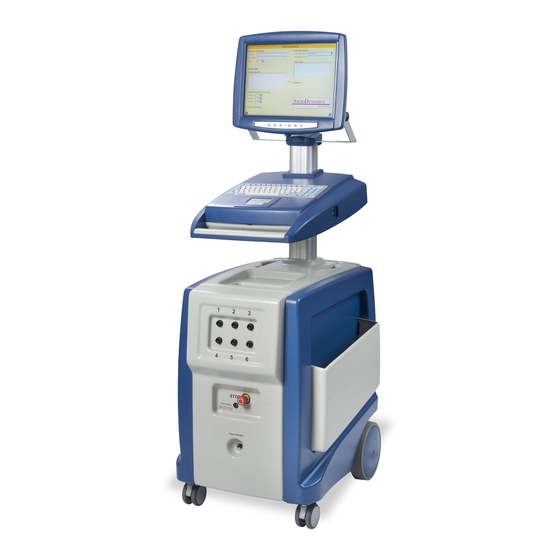
YSTEM OMPONENTS S E C T I O N Overview The NanoKnife System Generator utilizes single-use disposable electrode probes to transmit energy from the Generator to a target ablation area. The Generator Trolley in includes the following: Figure 3‐1... -
Page 18: Generator Description
Figure 3-1: Generator Trolley Generator Description The User’s interaction with the Generator is similar to utilizing a personal computer; the User operates the Generator through the console and LCD display. The console includes a conventional keyboard with Power-On, Caps Lock and Hard Disk Drive function light indicators, a touch pad with two buttons, and two USB ports located on the right side panel. -
Page 19: Generator Front/Lower Panel Elements
3.2.2 Generator Front/Lower Panel Elements There are four front/lower panel elements of the Generator as shown in Figure 3-3 and described in Table 3-2. Figure 3-3: Generator Front/Lower Panel Elements Table 3-2: Generator Front/Lower Elements Refer to Component Description Figure 3‐3 Six Electrode Connectors... -
Page 20: Generator Power Unit's Back/Lower Panel Elements
3.2.3 Generator Power Unit’s Back/Lower Panel Elements The power unit of the Generator performs all procedure activity for ablation delivery and measurement. The operator interacts with the power unit through the double foot pedal that starts the procedure. Figure 3-4 and Table 3-3 provide details on the Generator’s back view features. -
Page 21: Generator Back Handle
Power Cord Optional Electrodes (Purchased separately) NOTE: The Double Foot Pedal is an essential part of the NanoKnife. It is graded IPX-8. It is recommended to use only genuine parts supplied by the NanoKnife’s manufacturer or authorized distributor. 160-104694 Rev 01... -
Page 22: Lcd Display Controls Description
3.2.6 LCD Display Controls Description Each of the seven display control buttons are shown in Figure 3-6 and described in Table 3-5. Figure 3-6: LCD Display Control Buttons Table 3-5: LCD Display Controls Description Refer to Symbol Function Description Figure 3-6 Auto Press and the monitor will automatically optimize AUTO... -
Page 23: Lcd Display Settings
3.2.7 LCD Display Settings The viewing angle of the LCD display ranges from 45° forward to 90° backward. The display is supplied with control buttons to adjust its settings (see Table 3-6 for details.) Table 3-6: LCD Display Settings Refer to Figure LCD Setting Instructions ... -
Page 24: Console Components
3.2.8 Console Components There are six console components on the Generator that are shown in Figure 3-7 and described in Table 3-7. Figure 3-7: Console Components Table 3-7: Console Component Description Refer to Component Description Figure 3-7 Console Power-ON When lighted indicates that the system indicator identified by the ... -
Page 25: Electrode Probe Components
3.2.9 Electrode Probe Components The electronic probe components shown in Figure 3-8 are comprised of the following: 1. Active electrode, length adjustable in 0.5 cm increments from 0 – 4 cm via the thumbslide 2. Thumbslide 3. Insulation sleeve 4. 19-gauge needle with depth markers and echogenic needle tip 5. -
Page 26: Version 2.2.0
160-104694 Rev 01 Version 2.2.0... -
Page 27: Installation And Start U P
NSTALLATION S E C T I O N TART System Location The Generator must be installed and operated in an environment that conforms to the operating conditions specified in Section 10.4. The Generator must be installed on rigid surfaces suitable to withstand its weight. -
Page 28: Generator Start-Up And Warm-Up
• Connect the plug to a main outlet with protective ground. • Turn ON the Generator via the Main switch of the Power Supply Group, located on the power unit’s back panel. The system is ON when the main switch is pressed in "I"... - Page 29 Figure 4-2: Start-Up Screen Successfully Passed All Check Points If one of the Generator’s self tests fails, an error message will be displayed. Figure 4-3 is an example of an error message. The User must then click OK, which will shut down the generator, so that it can be restarted. Figure 4-3: Example of Error Message If a Self Test Fails If all self tests are successful, the Information screen (see Figure 5-1) then appears next on the LCD display.
- Page 30 160-104694 Rev 01 Version 2.2.0...
-
Page 31: Operation
YSTEM PERATION S E C T I O N Overview Procedure Main Steps An overview of the ablation procedure process is listed below: 1. Enter patient information. 2. Enter lesion and target size. 3. Connect probes to the Generator by means of the electrode connectors. -
Page 32: 5.1.1 Table Of Buttons
5.1.1 Table of Buttons Exit button on the Information screen quits the application and shuts down the generator. About button on all screens opens the About dialog box, which provides contact information, software, generator firmware, and RFID firmware versions, and TPM serial ... - Page 33 Zoom Out button on the Probe Placement Process screen decreases the magnification of the grid view. Adjust Distance button on the Probe Placement Process screen opens the Probe Distance Adjuster − A solver that allows the User to enter probe distances ...
-
Page 34: Information Screen
5.1.2 Information Screen The Information screen (Figure 5-1) is the first screen displayed when the Generator is powered on and the automatic self-checks are successfully completed. It includes the following four sections: Patient Information, Case Information, Clinical Data, and an Institution section that are described in following paragraphs. - Page 35 ▪ Procedure Date – The Procedure Date and Time are automatically set by the system. ▪ Physician Name – Optional ▪ Case Notes – Optional The Clinical Data section allows the User to type clinical information and tissue specifications in the appropriate fields. ▪...
- Page 36 The Institution section shows the name and contact information of the institution who purchased the system. Only an authorized AngioDynamics Hardware service representative can update this information, Figure 5-4 Figure 5-4: Institution Section To complete the Information screen and progress to the Probe Selection Screen, the User will need to enter the necessary information in the Information screen as described below.
- Page 37 The Clinical Data section − Clinical indication is an optional field and is used to capture clinical information. The Lesion zone, Margin and Pulse Timing Control are the three areas that will need to be completed in the Information screen by selecting the desired configurations, Figure 5-7.
- Page 38 To change the lesion settings, start with the Length field and change the value by typing entering a new one through the keyboard, using the Up or Down arrow keys on the keyboard, or using the Up and Down arrow keys on the popup. Repeat the process for the Width and Depth fields.
- Page 39 The Case Information section contains the Procedure date and time, which is automatically set. Physician name and Case notes are optional areas to complete, Figure 5-13. Figure 5-13: Case Information Screen After completing the Information section, select the next button (Figure 5-14) to proceed to the Probe Selection screen to select the probe type configuration for ablation.
-
Page 40: Probe Selection Screen
5.1.3 Probe Selection Screen The Probe Selection screen allows the User to select the number and the configuration of the ablation probes. The screen consists of three sections: Probe Type, Probe Type Side and Top Views, and a Probes Connection Status section Figure 5-15. Figure 5-15: Probe Selection Screen NOTE: Diagram shown for example only;... - Page 41 Three probe array, Four probe array, Five probe array, Six probe array, Six probe array 10 mm and Six probe array 15 mm. (NOTE: Bipolar probe type is not commercially available. If Bipolar is requested, AngioDynamics must be notified and authorization given from Clinical Sales.) The Probe Side and Top Views provide a horizontal and vertical cross-sectional representation of the ablation zone that will be affected by the probe(s) configuration.
- Page 42 Three Probe Array Four Probe Array Five Probe Array 160-104694 Rev 01 Version 2.2.0...
- Page 43 Six Probe Array Six Probe Array 10 mm Six Probe Array 15 mm 160-104694 Rev 01 Version 2.2.0...
- Page 44 The Probes Connection Status indicates the location and number of probes connected to the generator. The generator will determine if the probes are valid and are available for a procedure. The User may select the specific probes to be used for the procedure by selecting on the probe number.
- Page 45 At least one of the valid probes selected must be an Activation probe or the User will not be able to progress to the next screen. Once connected, the system will take up to five seconds to determine probe validation. If the probe is valid it will have a working time of eight (8) hours, at which time they will become invalid.
-
Page 46: Probe Placement Process Screen
5.1.4 Probe Placement Process Screen The Probe Placement Process screen is where ablation parameters are defined and ablation Pulse Settings are set. It consists of the Probe Placement Grid, Procedure Spreadsheet, Voltage Default Setting Box, Probe Dock/Undock and Exposure Table, and the Hints Text Box, Figure 5-19. - Page 47 Examples of each of the eight standard Probe type options are shown in Figure 5-20 below that the User can choose based on the size of the ablation and the number of probes required to treat the area in the Probe Placement Process screen. Biopolar Probe Two Probe Three Probe...
- Page 48 The P Probe Place ement Grid is a 7 x 7 cm m grid that is s displayed o on the upper r left corner the P Probe Placem ment Proces ss screen as shown in F igure 5-21. T This screen allows the U User...
- Page 49 Figure 5-23: : Show or Hid de Distances The S Show Distan nces feature allows the U User to switc ch the refere ence point to o a specific fiduci ial or probe. To set the r reference po oint, click on a fiducial or r probe.
- Page 50 Ablation Zone Voids: The Black outline inside the ablation zone. Depending on the location of the probes and the voltage selected, the void may be large or small (see Figure 5-25). In some cases, the void may be a single Black dot within the Ablation Zone.
- Page 51 Initial Set-up First Ablation Completed Figure 5-26: Example of Overlapping Ablation Procedure Using a Five Probe Array Probe Adjustment (4&5) Second Ablation Completed Figure 5-27: Moving Probes 4 and 5 to cover the Lesion Zone Buttons are in the screen under the placement grid as shown in Figure 5-28. Figure 5-28: Screen Buttons The Zoom In and Zoom Out buttons enlarge or decrease views of grid, to display a 7 x 7 view or a 5 x 5 view.
- Page 52 Figure 5-29: Autoset Probe Pop-Up Window Save ablation button is use with “Overlapping Ablations” to save the current ablation zone so that it can be referenced with other ablation zones as shown in Figure 5-30 Figure 5-30: Save Ablation or Do Not Save Ablation Clear ablation button will remove all the save ablation zones.
- Page 53 The Orange cell indicates the Generator is at the 3000 maximum output voltage, 3000 V or the distance between probes is greater or equal to 2 cm. The Light Blue cell indicates the Generator is at the minimum output voltage, 500 V. The White cell indicates values that can be changed.
- Page 54 1. Select the Edit Button below the Procedure Spreadsheet. 2. Select the Adjust Dist button. When the Adjust Dist button actuated, the Probe Distance Adjuster will appear. 3. Input the desired distances between probes, see Figure 5-33, into the white boxes of the Probe Distance Adjuster.
- Page 55 6. Click the Apply button when completed with edits. NOTE :If the User tries to proceed to another screen without selecting the “Apply” button the below error box will appear as shown in . Select OK Error! Reference source not found.5 and then select on the Apply Button. Figure 5-35: Error Box Add or Delete Rows allows the User to add or delete Rows in the Procedure Spreadsheet.
- Page 56 3. Select the minus button to delete the Row. 4. Confirm deletion by clicking the Yes button, Figure 5-38. Figure 5-38: Deletion Confirmation Box 5. Click Apply when finished NOTE #2: When a Row is deleted, the procedure may not be sufficient to fully cover the lesion.
- Page 57 Voltage Default Setting Box allows the User to change the Volts/cm setting with the Up/Down arrows to the desired volts/cm, Figure 5-40 Figure 5-40: Voltage Default Setting Box The Volts/cm Type allows the User to select either "Linear" process or "Non-Linear Lookup," depending on the type of tissue being treated, by selecting the adjacent radio buttons.
-
Page 58: Pulse Generation Screen
following are the main steps for probe placement: The Image the ablation zone either by standard imaging technologies or direct visualization. Prior to placing the probes, set the probe exposure to the required depth of ablation zone. Be sure to insert all probes to the ablation zone tissue depth. Apply the probes to the ablation zone, reproducing the probe configuration on the grid. - Page 59 Figure 5-43: Pulse Generation Screen The Run Section prepares, controls, and runs the ablation delivery. It displays several controls and messages according to the status of the ablation progress. Deliver Test Pulse button launches a low-voltage test pulse to the ablation site to confirm that the electrical pathway between the electrodes is within the operating ranges for impedance.
-
Page 60: Ablation Delivery
The Charge Section controls the voltage on the capacitors and displays the accumulated energy for ablation. The Capacitor Status Indictor displays the level of the capacitor charge and shows, in Volts the voltage present on capacitors. 5.1.6 Ablation Delivery After the probes have been placed and ablation parameters have been set, the User can initiate an ablation. - Page 61 Once the energy for the ablation has been accumulated, the following message appears in the status panel in Figure 5-45: "Device ready. Click arm pedal to ARM the device." Press the LEFT foot pedal to complete this action. Figure 5-45: Device Ready/Arm Device The system will arm and the message box prompt will show that the system is ready to deliver pulses.
- Page 62 The Procedure Parameters screen displays the probe parameters selected on the Probe Configuration table. When the "Pulse" pedal is pushed, the procedure starts for each pair listed in the Procedure Parameters table. See Figure 5-47: Total Pulses Delivered – The number of pulses delivered during the ablation sequence.
- Page 63 If the User presses "Abort" the procedure will stop (Figure 5-48). The complete and incomplete pairs will show in the status column. The User has a choice to "Continue Procedure" which will continue where the procedure left off, or "Stop Procedure" which will end the procedure.
- Page 64 Figure 5-49: Delivery Completed Screen Next, an Action Required pop-up screen will be displayed with the following message Figure 5-50: Export procedure files to USB? Select the "YES" or "NO" button. "YES" will forward the User to a My Computer window to select a file and USB port location and "No"...
- Page 65 At the end of the procedure, a pop-up panel may appear on the screen, showing events that may have occurred during the procedure. In particular, the following error messages may appear: An error message indicating that the procedure between specified electrode probes has been interrupted due to excessive current.
- Page 66 The Graphs on the Pulse Generation screen display the measured voltage and current waveforms of all the pulses delivered during the procedure. The Voltage graph displays the voltage waveforms measured during each pulse of the procedure as shown in Figure 5-52. The Current graph displays the current waveforms measured during each pulse of the procedure as shown in Figure 5-52.
-
Page 67: Additional Information
An additional left click on the either the voltage or current waveforms measured during the procedure allows the User to zoom in on the pulses corresponding to the position of the pointer. From the Result Graphs or Procedure Paramters screen, the User can directly access the Probe Placement Process screen to set a new procedure for the same patient by selecting the Back button, or go to the Probe Selection screen by selecting the New Probe button. - Page 68 Turn the power OFF at the main switch on the back panel of the Generator and then re-start. 5.1.7.2 Audible Indications The Generator produces three different audible indications: 1) before delivering a procedure (long beep), 2) during the procedure (double beep for each group of pulses), and 3) when the procedure is complete (double long beep).
- Page 69 Select "No" to skip exporting procedure files and the Application software will shut down. The software application closes and Windows shuts down. 5.1.7.5 System Shut Down To shut down the system select the Exit button on the Information screen, and select Yes on the popup.
- Page 70 160-104694 Rev 01 Version 2.2.0...
-
Page 71: External Ecg Synchronization
XTERNAL S E C T I O N YNCHRONIZATION Overview The Generator starts in the ECG Synchronous mode (default setting). When working in this mode, the Generator has to be connected to an external R-wave detector. External R-Wave Detector The external R-wave detector must have the following specifications: •... - Page 72 The Generator will deliver one IRE Pulse 50 ms after the rising edge of the triggering signal, provided that the triggering interval is greater than 500 ms. There are three conditions the ECG triggering signal may be in: ECG synchronized, ECG noisy, and ECG no signal.
- Page 73 Possible solutions "ECG no signal": • Verify that ECG cables are firmly connected to buttons. • Check the display of the synchronization device—is it generating a synchronization signal on each R-wave? Toggle different lead combinations on the synchronization device until a satisfactory synchronization signal is found. •...
- Page 74 If the ECG signal is synchronized DURING energy delivery, energy delivery will occur and the screen in Figure 6-5 will display: "Delivery in progress between probes 3-4…Please wait…" Figure 6-5: ECG Synchronized on Pulse Generation Screen During Energy Delivery If the ECG signal is slow or not present DURING the test pulse or energy delivery, the test pulse or energy delivery will stop and a 15-second countdown will begin.
- Page 75 Figure 6-7: ECG Noisy on Pulse Generation Screen During Energy Delivery If the ECG signal is not synchronized within the 15-second countdown, a 120-second countdown will begin. If the signal becomes synchronized during the 120-second countdown, the User will have the option to resume or abort the procedure. The following screen in Figure 6-8 will be displayed: Figure 6-8: ECG Synchronized on Pulse Generation Screen During 120-Second Countdown If the ECG signal is not synchronized within the 15-second countdown, a 120-second...
- Page 76 If the ECG signal is not synchronized within the 15-second countdown, a 120-second countdown will begin. If the signal remains fast for the 120 seconds, the following screen in Figure 6-10 will be displayed: Figure 6-10: ECG Noisy on Pulse Generation Screen During 120-Second Countdown If the ECG signal is not synchronized during the 120-second countdown or if it is synchronized and the User does not select the Resume button, the procedure will automatically abort.
-
Page 77: Probes And Ablation Area
Up to six single probes can be placed at a fixed distance apart in the tissue to create several two-pole electrode configurations. The Generator is only to be used with electrode probes supplied by AngioDynamics, Inc. Ablation Area Refer to the Ablation Zone, reference Section 5.1.4 Probe ... - Page 78 160-104694 Rev 01 Version 2.2.0...
-
Page 79: Trouble Shooting
ROUBLE SHOOTING S E C T I O N Overview The following tables delineate some of the process problems and error messages of the NanoKnife System and how to address them. 160-104694 Rev 01 Version 2.2.0... -
Page 80: Documented Problems And Solutions
Documented Problems and Solutions Table 8-2: Problems and Solutions Malfunction Possible Reasons Actions Generator unplugged Check that the main power supply from the main or main cord is connected to cord connector outlet not powered. on the power unit back panel and ... -
Page 81: Error Messages
Repeat any portions of ablation that unit. were not delivered. If the auto-test fails, call AngioDynamics Hardware Service. Time Expired The 10 seconds Press the ARM foot pedal again to timeout between the restart a new ablation sequence. - Page 82 The system detected a Reboot the system to let the auto-test Correct Pulse pulse that is too long. check the system. If the auto-test fails, call AngioDynamics Hardware Service. Unable to Complete The system detected a Reboot the system to let the auto-test...
-
Page 83: Maintenance And Service
Overview This section describes the recommended periodical checks and preventive maintenance that the User should complete to ensure that the NanoKnife System will satisfactorily perform its intended function. There are no User-serviceable parts inside the Generator. The warranty will be voided if the unit is opened and/or the warranty seal is broken. -
Page 84: Preventive Maintenance And Periodical Verifications
Preventive Maintenance and Periodical Verifications The following Table 9-1 indicates the recommended periodical checks and preventative maintenance. Table 9-1: Generator Periodical Checks Test/Service Time Interval Rationale Maintenance calibration Annual Service 12 Months required every 12 months by ... - Page 85 The device has protection fuses on the main power supply. The fuses are seated inside the Power Supply Group, i.e., close to the Main Switch. Figure 9-2: Power Supply Group Hosting Main Fuses To replace the main fuses, perform the following steps: 1.
- Page 86 160-104694 Rev 01 Version 2.2.0...
-
Page 87: Technical Data
ECHNICAL S E C T I O N The technical data defined in this section contain the overall system and functional specifications of the NanoKnife Generator. 10.1 General Information Generator Model: HVP01 Manufacturer of HVP01 (NanoKnife System) AngioDynamics, Inc. 14 Plaza Drive... -
Page 88: Fuse Type Specifications
(Note: Temperature must be from -20° to +60° C because the Non-Operating temperature range for a new ATX Power Supply is from -20°C to +80° C and the Storage Temperature of the NanoKnife Touch-Screen Monitor is specified as -20° C to +60° C.) -
Page 89: Use Conditions
10.5.3 Ingress of Liquids IPX0 – No Special Protection Footswitch: IPX8 10.5.4 Safety Level The Generator is NOT SUITABLE to be employed within the regions where flammable anesthetic mixtures may be present, specified by EN 60601-1. 10.5.5 EEC 93/42 Classification Hazard Class: Class IIb 10.5.6 FDA Classification... -
Page 90: Radio Frequency Identification
10.8 Radio Frequency Identification FCC ID: YHS-600-104443 The RFID card with its FCC ID label is located inside the NanoKnife generator. The RFID antennas are located around the probe connectors on the front panel of the device. This device complies with part 15 of the FCC Rules. Operation is subject to... -
Page 91: Section 11 Warranty And Electromagnetic Compatibility
OMPATIBILITY 11.1 Warranty The NanoKnife System Generator is warranted to be free from defects of materials and workmanship under normal and proper use for a period of twelve months. Full details of this limited warranty are described in the 12-Month Limited Warranty &...