
Related Manuals for Toro Flex-Force Power System 51895T


Summary of Contents for Toro Flex-Force Power System 51895T
- Page 1 Form No. 3469-733 Rev B Flex-Force Power System ® 60V MAX String Trimmer Model No. 51895T—Serial No. 324000000 and Up *3469-733* Register at www.Toro.com. Original Instructions (EN)
- Page 2 You are responsible for operating the product properly and safely. Visit www.Toro.com for product safety and operation training materials, accessory information, help finding a dealer, or to register your product.
- Page 3 Whenever you need service, genuine the manufacturer parts, or additional information, contact an Authorized Service Dealer or the manufacturer Customer Service and have the model and serial numbers of your product ready. Figure 1 identifies the location of the model and serial numbers on the product.
-
Page 4: Safety Alert Symbol
Safety-Alert Symbol The safety-alert symbol (Figure 2) shown in this manual and on the machine identifies important safety messages that you must follow to prevent accidents. g000502 Figure 2 Safety-alert symbol The safety-alert symbol appears above information that alerts you to unsafe actions or situations and is followed by the word DANGER, WARNING, or CAUTION. - Page 5 Safety WARNING Read all safety warnings, instructions, illustrations and specifications provided with this machine. Failure to follow all instructions listed below may result in electric shock, fire and/or serious injury. Save all warnings and instructions for future reference. The term “machine” in all the warnings refers to your mains-operated (corded) machine or battery-operated (cordless) machine.
- Page 6 When operating a machine outdoors, use an extension cord suitable for outdoor use. Use of a cord suitable for outdoor use reduces the risk of electric shock. If operating a machine in a damp location is unavoidable, use a residual current device (RCD) protected supply. Use of an RCD reduces the risk of electric shock.
- Page 7 IV. Machine use and care Do not force the machine. Use the correct machine for your application. The correct machine will do the job better and safer at the rate for which it was designed. Do not use the machine if the switch does not turn it on and off. Any machine that cannot be controlled with the switch is dangerous and must be repaired.
- Page 8 V. Battery tool use and care Recharge only with the charger specified by the manufacturer. A charger that is suitable for one type of battery pack may create a risk of fire when used with another battery pack. Use machines only with specifically designated battery packs. Use of any other battery packs may create a risk of injury and fire.
- Page 9 VII. String Trimmer safety Do not use the machine in bad weather conditions, especially when there is a risk of lightning. This decreases the risk of being struck by lightning. Thoroughly inspect the area for wildlife where the machine is to be used.
- Page 10 exercise extreme caution when changing direction. This reduces the risk of loss of control, slipping and falling which may result in personal injury. Keep all power cords and cables away from cutting area. Power cords or cables may be hidden in hedges or bushes and can be accidentally cut or damaged by the line or cutter.
-
Page 11: Safety And Instructional Decals
Safety and Instructional Decals Safety decals and instructions are easily visible to the operator and are located near any area of potential danger. Replace any decal that is damaged or missing. decal161-7098 161-7098 1. Warning—keep 2. Thrown object decal161-7083 bystanders hazard—keep 161-7083 away from the... - Page 12 decal161-7080 161-7080 1. Do not dispose of improperly...
-
Page 13: Loose Parts
Setup Loose Parts Use the chart below to verify that all parts have been shipped. Procedure Description Qty. Connector knob Unfold the shaft. Install the auxiliary Auxiliary handle assembly handle. Guard Install the guard. Screw... - Page 14 Unfolding the Shaft Parts needed for this procedure: Connector knob Procedure Unfold the shaft (A of Figure Secure the shaft together at the coupler using the connector knob (B of Figure g507675 Figure 3...
-
Page 15: Installing The Auxiliary Handle
Installing the Auxiliary Handle Parts needed for this procedure: Auxiliary handle assembly Procedure Separate the auxiliary handle from the handle bracket by unscrewing the handle-lock knob and removing the bolt (A of Figure Important: The bolt may be wedged into the plastic of the handle;... -
Page 16: Installing The Guard
Installing the Guard Parts needed for this procedure: Guard Screw Procedure Secure the guard onto the base of the trimmer with the 2 screws. g507687 Figure 5... -
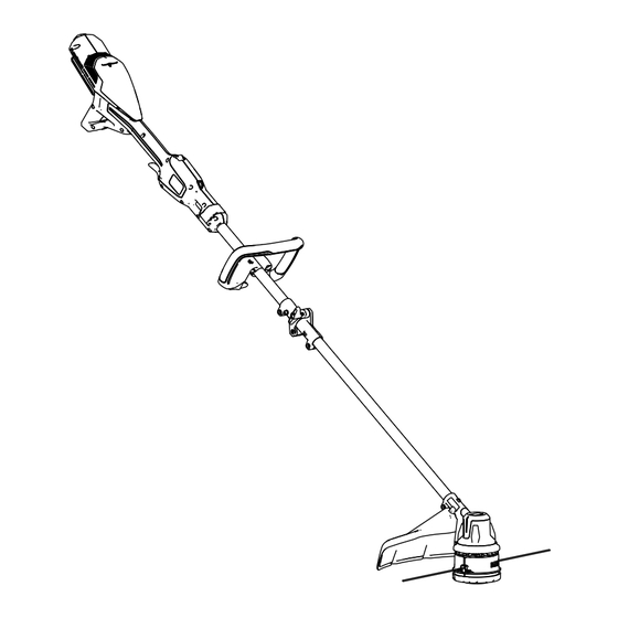
Page 17: Product Overview
Product Overview g507020 Figure 6 1. Battery latch 6. Cutting line 2. Lockout switch 7. Guard 3. Telescoping latch 8. Run trigger 4. Auxiliary handle 9. Trimmer vents 5. Mid-shaft coupler... -
Page 18: Specifications
Store the tool, battery pack, and battery charger in an enclosed clean, dry area. Attachments/Accessories A selection of Toro approved attachments and accessories is available for use with the machine to enhance and expand its capabilities. Contact your Authorized Service Dealer or authorized Toro distributor or go to www.Toro.com for a list of all approved attachments and accessories. -
Page 19: Operation
Operation Starting the Trimmer Ensure that the vents on the trimmer are clear of any dust and debris. Align the cavity in the battery pack with the tongue on the power head (Figure Push the battery pack into the power head until the battery locks into the latch (Figure g507688... - Page 20 Shutting Off the Trimmer To shut off the trimmer, release the trigger and the lockout switch. Whenever you are not using the trimmer or are transporting the trimmer to or from the work area, remove the battery pack. Removing the Battery Pack from the Trimmer Press the battery latch to release the battery pack and slide the battery pack out of the machine (Figure...
- Page 21 Adjusting the Auxiliary Handle Position Loosen the handle-lock knob on the bottom of the auxiliary handle. Adjust the position of the auxiliary handle on the shaft until the trimmer can held in a neutral, comfortable position while operating. Tighten the handle-lock knob to secure auxiliary handle in place. Adjusting the Shaft Length Open the telescoping latch at the front of the handle.
-
Page 22: Advancing The Line Manually
Advancing the Line Using the Bump Feed Run the tool at full throttle. Tap the bump head on the ground to advance the line. The line advances each time the bump head is tapped. Important: Do not hold the bump head on the ground while running the trimmer. - Page 23 Using the Shoulder Harness Important: If you are using the string trimmer with a 8.0 Ah or greater battery pack installed, install a shoulder harness (not included). Do not use the shoulder harness if you are powering the string trimmer with the backpack and backpack tether; use only the backpack harness.
- Page 24 Allow the buckle to disconnect (B of Figure 13). g340477 Figure 13...
-
Page 25: Operating Tips
Operating Tips • Keep the trimmer tilted toward the area being cut; this is the best cutting area. • The string trimmer cuts when you move it from right to left. This prevents the trimmer from throwing debris at you. •... -
Page 26: Maintenance
Replacing the Cutting Line Use only 2.0 mm (0.080 inch) diameter monofilament cutting line or 2.4 mm (0.095 inch) diameter twisted monofilament cutting line from Toro. Remove the battery pack from the trimmer. Remove any existing line on the spool by repetitively pressing the bump head while pulling the line out equally from both sides of the bump head. - Page 27 Insert 1 end of the line straight into the eyelet and push the line through until it comes out of the eyelet on the other side. g507694 Figure 15 1. Cutting line 3. Eyelet alignment mark 2. Eyelet 4. Bump head alignment mark Important: Do not disassemble the trimmer head.
- Page 28 Replacing the Trimmer Head Remove the battery pack from the trimmer. Insert a small-diameter tool (such as a screwdriver) through the motor housing and into the groove in the fan to secure the trimmer head so it does not freely rotate (Figure 16).
- Page 29 With a tool securing the trimmer head, rotate the trimmer head counterclockwise to remove it from the threaded gearcase post (Figure 17). g516022 Figure 17 To install the new trimmer head, rotate it clockwise onto the gearcase post while securing the fan with a tool.
- Page 30 Storage Important: Store the machine, battery pack, and charger only in temperatures that are within the appropriate range; refer to Specifications (page 18). Important: If you are storing the machine for a year or longer, remove the battery pack from the machine and charge the battery pack until 1 or 2 LED indicators turn green on the battery.
-
Page 31: Troubleshooting
Troubleshooting Perform only the steps described in these instructions. All further inspection, maintenance, and repair work must be performed by an authorized service center or a similarly qualified specialist if you cannot solve the problem yourself. Always remove the battery from the tool when troubleshooting, inspecting, maintaining, or cleaning the tool. - Page 32 Problem Possible Cause Corrective Action The tool is producing 1. There is debris under 1. Clean any debris from excessive vibration or the grass shield or in under the grass shield noise. the bump head housing or in the bump head on the trimmer.
Need help?
Do you have a question about the Flex-Force Power System 51895T and is the answer not in the manual?
Questions and answers