
Related Manuals for Hopewind HSNV25K-G01


Summary of Contents for Hopewind HSNV25K-G01
- Page 1 User Manual String Inverter HSNV25K-G01, HSNV30K-G01, HSNV36K-G01, HSNV40K-G01, HSNV50K-G01 Date: 2024/4/2 Issue:...
- Page 2 Copyright© Shenzhen Hopewind Electric Co., Ltd. All rights reserved. Shenzhen Hopewind Electric Co., Ltd. owns the patents, copyrights, and other intellectual property rights of this product and its related software. No part of this manual may be reproduced, transmitted or used for other commercial purposes in any form or by any means without prior written consent of Hopewind.
-
Page 3: Intended Readers
Preface Preface Thank you for purchasing products developed and manufactured by Hopewind. We hope our product and this manual can meet your demands. Please read this manual carefully before using the product to ensure personal safety and better user experience, and it shall be kept safe for future reference. -
Page 4: Symbols And Conventions
Maximum power point tracking Maximum power point Photovoltaic string Multiple solar cell arrays in parallel or series EEPROM Electrically erasable programmable read-only memory hopeCloud Hopewind remote intelligent O&M cloud service platform Change History Issue Date Change Content 2024-04-02 First publish... -
Page 5: Table Of Contents
Contents Contents Preface ..........................I 1 Safety Precautions......................5 1.1 Transportation ......................5 1.2 Storage ........................6 1.3 Installation ........................6 1.4 Operation ........................7 1.5 Maintenance ........................ 8 2 Product Description ......................9 2.1 Product Introduction ....................9 2.1.1 Schematic Diagram ..................... 9 2.1.2 Working Mode ..................... - Page 6 Contents 4 Commissioning Guide ..................... 39 4.1 Check before Power-On ....................39 4.2 System Power-On ......................40 4.3 Commissioning through hopeCloud ................41 4.4 System Power-Off ......................47 5 Maintenance and Troubleshooting .................. 49 5.1 Maintenance Items and Cycles ..................49 5.2 Troubleshooting ......................50 6 Inverter Disposal ......................57 6.1 Removing the Inverter ....................57 6.2 Replacing the Inverter ....................57 6.3 Packing the Inverter ....................57...
-
Page 7: Safety Precautions
Safety Precautions 1 Safety Precautions In this chapter, it describes the safety precautions that must be observed when installing, operating and maintaining the inverter. Please read them carefully before operation and follow them in operation process; otherwise it might cause damage to the inverter, the generator and related equipment or cause serious injury or loss of life. -
Page 8: Storage
Safety Precautions 1.2 Storage The storage environment of the string inverter must meet the corresponding requirements. Please refer to 2.10 Ambient Requirements. About long-term storage: Before or after the installation and commissioning, if the string inverter is in the no- power supply state for more than three weeks, it is regarded as long-term storage. -
Page 9: Operation
Safety Precautions During installation and maintenance, it is necessary to prevent liquid, dust or debris from entering the inside of the string inverter. Conductive liquids and debris may cause internal short circuit of the string inverter, resulting in equipment damage. When connecting the wiring of the external cable to the string inverter, the ... -
Page 10: Maintenance
Safety Precautions 1.5 Maintenance Before maintenance work, you must first disconnect the AC output side circuit breaker, then disconnect the input switch DC Switch, and wait at least 5 minutes before operating the string inverter. During the maintenance process, try to avoid irrelevant personnel from ... -
Page 11: Product Description
2 Product Description 2.1 Product Introduction HSNV series three-phase string inverters are independently developed by Hopewind, whose main function is to convert the DC power generated by the PV string into AC power and feed it into the power grid. -
Page 12: System Configuration And Networking Application
Product Description Operating mode Description 1) Standby mode mainly means that the external environment does not meet the operating conditions of the inverter such as insufficient light and the disconnection of DC input switch. In this mode, the inverter continuously self-tests and enters the operating mode once Standby the operating conditions are met. -
Page 13: Supported Power Grid Types
PV arrays Figure 2-4 Networking scheme of distributed PV power station 2.2.2 Supported Power Grid Types The power grid forms supported by HSNV25K-G01, HSNV30K-G01, HSNV36K-G01, HSNV40K- G01, and HSNV50K-G01 include TN-S, TN-C, TN-C-S, TT, IT. TN - S TN - C... -
Page 14: Nameplate
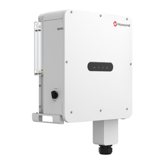
2.4 Nameplate The information in the nameplate is for reference only. The actual product and technical agreement shall prevail. Shenzhen Hopewind Technology Co., Ltd. is a wholly-owned subsidiary of Shenzhen Hopewind Electric Co., Ltd. 2.5 Inverter Configuration This section describes the internal components, back components and bottom interfaces of the string inverter. - Page 15 Product Description Device name Door panel LED indicator Figure 2-7 Front view of the inverter The LED indicators from left to right are described as follows: Table 2-1 LED Indicator Description Indicator light Meaning Status Description Blue light on PV side and grid connected normally Grid connected normally while PV side Blue light fast blinking...
- Page 16 Product Description Label Device name Mounting bracket Mounting plate Figure 2-8 Back view of the inverter Label Device name DC SWITCH DC switch PV+ terminal Wi-Fi Wi-Fi port RS485-2 Zero export and EPO/NS port PV- terminal RS485-1 RS485 communication port AC OUTPUT AC output port Issue 1.0 (2024-04-02)
-
Page 17: Labels On The Package
Product Description 2.6 Labels on the Package On the outer packaging of the product, there are some labels to guide the user to transport and store the product. The meanings indicated by the logo are as follows: Handle with care. Avoid damage to the converter caused by intense No stacking... -
Page 18: Technical Parameters
Product Description 2.8 Technical Parameters Model HSNV25K-G01 HSNV30K-G01 HSNV36K-G01 Maximum input voltage 1100 V Minimum working 180 V voltage Working voltage range 200–1000 V MPPT full load working 375–850 V voltage range Input Rated input voltage 650 V parameters Maximum input current... - Page 19 Product Description test AC short circuit Supported protection Output surge Class II protection String fault detection Supported RCD detection Supported Arcing detection Supported N to PE voltage Supported detection EPO/NS Supported Display LED + APP RS485 communication Supported Display Zero export communication Supported communication...
- Page 20 Product Description voltage range Rated input voltage 650 V Maximum input current 54 A/54 A 60 A/60 A per MPPT Maximum short circuit 81 A/81 A 90 A/90 A current per MPPT Maximum input ways Number of MPPT Rated output power 40 kW 50 W Maximum output...
- Page 21 Product Description N to PE voltage Supported detection EPO/NS Supported Display LED + APP RS485 communication Supported Display Zero export communication Supported communication Communication port Wi-Fi/RS485 + APP Dimensions (W * H * D) 560 x 823 x 307 Weight 55 kg -40℃...
-
Page 22: Mechanical Parameters
Product Description 2.9 Mechanical Parameters Dimension and Weight Model Width * height * depth (mm) Net weight (kg) HSNV25K-G01 HSNV30K-G01 HSNV36K-G01 560 x 823 x 307 HSNV40K-G01 HSNV50K-G01 Dimension of the inverter here does not contain hangers, handles, pads and other components. -
Page 23: Ambient Requirements
Product Description 2.10 Ambient Requirements Transportation Requirements environment Type of shipping Waterways, railways, highways, aviation, etc. Ambient -40℃ to +70℃ temperature Relative humidity ≤ 95% when the temperature is +40℃ The vibration should not exceed the following limits: Mechanical 2 Hz ≤ f < 9 Hz, displacement 7.5 mm. condition 9 Hz ≤... -
Page 25: System Installation
System Installation 3 System Installation 3.1 Receiving Inspection After confirming that the outer packaging is intact, please carry out the unpacking inspection. Unpack the packaging box and check whether the appearance of the string inverter is in good condition. When opening the package, be careful to use the tool to avoid scratching the string inverter. -
Page 26: Installation Environment Requirements
System Installation Earplugs Vacuum cleaner Utility knife Monkey wrench Cable tie Figure 3-1 Installation Tools Preparation 3.3 Installation Environment Requirements The environmental requirements for the installation of string inverter are shown in "1 Safety Precautions". The installation mode and position must be suitable for the weight and dimension of the ... -
Page 27: Installation Angle
System Installation When installing multiple inverters in a same surface, the horizontal installation mode is recommended. Figure 3-3 Horizontal installation mode When installing multiple string inverters in two lines, the triangle installation is recommended. Figure 3-4 Triangle installation space 3.5 Installation Angle Figure 3-5 Installation Angle Issue 1.0 (2024-04-02) -
Page 28: Installation Method
System Installation 3.6 Installation Method To install the inverter, please install the mounting plate first, and then hang the inverter to the mounting plate and fix it. You can mount the inverter on the wall or the bracket according to the actual requirements. -
Page 29: Electrical Connections
System Installation Step 2 Install the mounting bracket to the inverter. Figure 3-8 Hang the inverter on the mounting plate Step 3 4. Hang the mounting bracket of the inverter to the mounting plate and fix it with screws to prevent it from shaking. Figure 3-9 Secure the inverter with screws 3.7 Electrical Connections 3.7.1 Cable Requirements... - Page 30 System Installation Communication cable requirements Since weak communication signals are susceptible to external interference, the communication cable requires a shielded cable with the shield grounded as shown in the following figure. Figure 3-10 Double-shielded When double shielding layers are adopted, both twisted pair ends of the outer shielding layer need to be grounded, and one end of the inner shielding layer...
-
Page 31: Cable Selection
1600 2000 kgf.cm The performance rating for all the bolts with a nominal external thread diameter of 8 mm and above used by Hopewind’s string inverters is 8.8. Issue 1.0 (2024-04-02) -
Page 32: Preparation Before Operation
System Installation 3.7.4 Preparation before Operation When connecting cables, do not operate when the product is energized and please follow the relevant requirements in 1 Safety Precautions. Before connecting the cables, please complete the following preparations to avoid personal injury. 1) Before electrical connections, please make sure that the "DC SWITCH"... -
Page 33: Connecting Dc Input Cables
System Installation For the grounding of multiple string inverters, use single-point grounding instead of winding the ground wire into a ring shape as shown below. Figure 3-13 Correct grounding method for Figure 3-14 Wrong grounding method for multiple string inverters multiple string inverters 3.7.6 Connecting DC Input Cables In order to make full use of the DC input power, the PV strings of the same input MPPT... - Page 34 System Installation The maximum opening voltage of each PV string cannot be greater than 1100 V DC under what circumstances. The maximum short-circuit current of each PV string shall not exceed 30 A under any conditions. Ensure that the polarity input on the DC input side is correct, that is, the positive ...
- Page 35 System Installation Figure 3-16 Crimp the terminal Step 3 Disassemble the DC connector. Figure 3-17 Disassemble the DC connector Step 4 Thread the cable through the connector then reassemble the connector. Figure 3-18 Reassemble the connector Step 5 Measure the DC voltage and check the polarity of the connectors. Figure 3-19 Check the polarity of the connectors Step 6 Remove the sealing plugs of the DC terminals.
-
Page 36: Connecting Ac Output Cables
System Installation Figure 3-21 Connect the connectors Please use the MC4 terminals configured in the delivery accessories. Device damage due to use of incompatible MC4 terminals is not covered by the warranty. After the cable connection of the string inverter is completed, check if there is a gap at the waterproof lock. - Page 37 System Installation Step 2 Install the cable gland, unscrew the locking cap, and then thread the cables through the locking cap. Figure 3-23 Remove the lower panel Step 3 Remove the screws fixing the AC wiring terminal, align the cables with the holes and tighten the screws.
-
Page 38: Connecting Communication Cables
System Installation 3.7.8 Connecting Communication Cables RS485 communication cable making Step 1 Strip the communication cable. Figure 3-26 Strip the communication cable Step 2 Crimp the cable with the wiring terminal. Figure 3-27 Crimp the communication cable Cable connection The inverter can be connected to the communication equipment (such as a data collector or a PC) through the RS485 communication cable. - Page 39 System Installation Table 3-2 RS485-1 8-PIN terminal Definition Definition RS485-1+ Terminal Resistor RS485-1+ RS485-1- Terminal Resistor RS485-1- The connection of multiple inverters is suggested to be connected in series, as shown in the figure below. 8-pin port 8-pin port 8-pin port 485 Port 485 Port Data collector...
-
Page 40: Connecting The Wi-Fi Module
System Installation 3.7.9 Connecting the Wi-Fi Module Users can connect the inverter to hopeCloud through the communication module, which makes it convenient for users to remotely view or set the relevant parameters of the device, and timely understand the system status. For specific installation and operation instructions of the Wi-Fi module, please refer to the quick installation guide delivered with the product, or scan the QR code below to obtain the electronic file. -
Page 41: Commissioning Guide
Commissioning Guide 4 Commissioning Guide 4.1 Check before Power-On Before proceeding to the next step of power on, please read carefully this manual "1 Safety Precautions" and do a detailed check according to the table below. In order to avoid danger, the multimeter and other instruments must be used to ... -
Page 42: System Power-On
Commissioning Guide 4.2 System Power-On After ensuring that the electrical connection is completed, the power on operation can be performed and the inverter will be turned on. Step 1 Set the DC SWITCH of the inverter to the “ON” state. Step 2 Close the AC circuit breaker between the inverter and the power grid. -
Page 43: Commissioning Through Hopecloud
Commissioning Guide 4.3 Commissioning through hopeCloud Before commissioning, please ensure that the Wi-Fi module has been connected and hopeCloud has been downloaded and installed (including registration, creation of the power station, addition of devices and network configuration). Please refer to 3.7.9 Connecting the Wi-Fi Module for more details. - Page 44 Commissioning Guide Step 5 Function settings > Parameter Settings to enter the setting page. Click Select and set corresponding parameters according to on-site requirements by referring to the table below. Table 4-1 Function list Parameter Function Arcing detection enable (A)DC side configuration IV scan enable MPPT mutual learning enable (B)PID configuration...
- Page 45 Commissioning Guide Function (D) 1) Zero export principle A zero export meter is installed on the main line of the house-service wire, through which the real-time power and current level and direction are collected. When the data collector detects that there is current flowing to the grid, it sends a command to adjust the inverter output power.
- Page 46 Commissioning Guide Login. Step 2 Select Plant on the home page and tap > Inverter. Search the SN of the inverter in the search box and tap Search. Step 3 After entering the detail page of the inverter, tap > Parameter Settings >Zero export.
- Page 47 Commissioning Guide Users can follow the steps below if using the hopeCloud APP to set the zero export function. Step 1 Open the APP and tap > Server > International Server. Enter the account and password, check “I have read and agreed to Service Terms and Privacy Policy” and tap Login.
- Page 48 Commissioning Guide The zero export power and CT transformation ratio should be set according to the onsite conditions. DRM Function According to AS NZS 4777.2-2015, inverters shall support the demand response modes (DRMs). HSNV inverters support the mandatory DRM0 by providing the EPO protection function and other optional demand response modes can be realized when inverters communicate with the data collector through RS485 communication.
-
Page 49: System Power-Off
Commissioning Guide 4.4 System Power-Off Precautions After the inverter is powered off, there will be residual electricity and residual heat on the enclosure, which may cause electrical shock or burns. Therefore, please wait at least 5 minutes before you operate the inverter. When powering off the system, please follow the sequence of operation instructions and ... -
Page 51: Maintenance And Troubleshooting
Maintenance and Troubleshooting 5 Maintenance and Troubleshooting 5.1 Maintenance Items and Cycles Please read 1 Safety Precautions carefully before maintenance, and use a multimeter and other relevant instruments to detect the voltage between the metal parts that need to be or maybe touched and the grounding copper bars so as to avoid electric shock. -
Page 52: Troubleshooting
Auxiliary power normally after reset power supply is too failure 2. If it occurs frequently, please high or too low contact the Hopewind technician The output voltage 1. Check whether it can work Output hardware exceeds the normally after reset... - Page 53 2. If it occurs frequently, please wave-by-wave contact the Hopewind technician current limit time EEPROM EEPROM read and parameters back Fault reset or power off write error to default values...
- Page 54 RAM self test Check RAM chip read 2. If it occurs frequently, failed and write error please contact the Hopewind technician Add EEPROM parameter list and upgrade the 1. Check whether it can work EEPROM code again. After...
- Page 55 Bus voltage exceeds normally after reset hardware hardware overvoltage 2. If it occurs frequently, overvoltage threshold please contact the Hopewind technician 1. Check whether it can work Bus midpoint voltage normally after reset Busbar midpoint exceeds hardware 2. If it occurs frequently,...
- Page 56 Maintenance and Troubleshooting Fault Fault/alarm Fault/alarm reason Troubleshooting word name 1. Confirm whether the box transformer tripping and other faults occur on the AC The grid frequency is side of the inverter through Grid lower than the fault recording and event underfrequency underfrequency point recording...
- Page 57 1. Check whether it can work normally after reset Bus operation Bus voltage sag 2. If it occurs frequently, short circuit exceeds limit please contact the Hopewind technician 1. Check whether it can work The bus voltage normally after reset Bus operation exceeds the set 2.
- Page 58 1. Check whether it can work normally after reset Grid-connected Relay status error 2. If it occurs frequently, relay failure please contact the Hopewind technician Other 1. Check whether it can work normally after reset Fan failure or abnormal Internal fan fault 2.
-
Page 59: Inverter Disposal
When the service life of the inverter expires or the inverter is replaced due to faults, please dispose it according to the local rules for electrical equipment waste disposal or hand over it to Hopewind customer service personnel. Issue 1.0 (2024-04-02) -
Page 61: Appendix
Appendix Appendix Warranty If the product has any fault in the warranty period, we will provide cost-free repair or replacement service. Any faults arising from the following conditions shall be out of the warranty: Dismantle the product without our permission or maintain in wrong way; ...
Need help?
Do you have a question about the HSNV25K-G01 and is the answer not in the manual?
Questions and answers