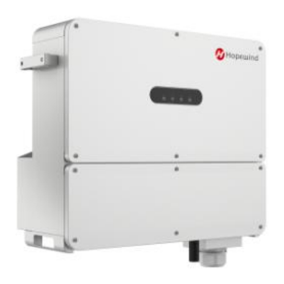
Hopewind hopeSun Series Quick Installation Manual
String type pv inverter
Hide thumbs
Also See for hopeSun Series:
- User manual (50 pages) ,
- Quick installation manual (2 pages) ,
- User manual (39 pages)
Advertisement
hopeSun Series
100KTL, 110KTL,
125KTL-M, 136KTL-M
String Type PV Inverter
Quick Installation Guide
CAUTION
1. The contents of this manual are subject to irregular updates
due to product upgrades or other reasons. Unless otherwise
agreed, this manual is only used as guidance. All statements,
information and recommendations in the document do not
constitute any express or implied warranty.
2. In any case, guidance in this manual cannot replace safety
warnings and instructions on user manuals and product
fuselage.
3. All operations of the equipment must be carried out by
professionals. Operators should be fully familiar with the
composition, working principles and standards of the whole
PV system.
4. Before installing the equipment, check whether the delivery is
complete and whether the body has obvious external damage
according to the "packing list". If there are any missing items
or any damage, please contact the distributor.
5. The following two situations occur and are not covered by the
warranty.
Remove the tamper-evident label;
Equipment damage caused by failure to store, handle,
install, and use the equipment in accordance with the
requirements of this manual and the user manual.
1. Product Introduction
Scope of Supply
Inverter
Hanging plate*
MC4 PV- jack
MC4 PV+ pin
+ pin
+ jack
4# Allen wrench
Waterproof lock
*The hanging plate is fixed on the back of inverter.
The documents including:
Quick Installation Guide (this manual)
List of Accessories
Inspection Report
Certification
For the model and number of the accessories, please
refer to the List of Accessories.
This figure is only for reference; please refer to the
actual product.
Inverter front
1
2
3
Port description
2
1
5
6
3
7
(1) DC SWITCHS
(2) PV- terminals
(3) PV+ terminals
(4) AC output terminal
(5) Wi-Fi/GPRS interface
(6) Anti-backflow interface
(7) RS485 interface
2. Installation Requirements
Installation Environment
Please install the inverter in a well ventilated
environment, avoid direct sunlight, rain and snow.
√Well ventilated
Ambient Temperature
(The inverter can reach the best working condition
when the temperature is lower than 40℃)
Inverter and hanging plate size
680mm
Weight≤90kg
Installation Space
The installation space of single inverter is as following:
M6/M8/M10
screw sets
M8 expansion bolt
When installing multiple string inverters in a same
surface, the side by side installation is recommended.
Documents
When installing multiple string inverters in two lines,
the triangle installation is recommended.
Please install it vertically or tilt it backward at most 15°
(1) Upper door
to facilitate the heat dissipation of the inverter. Do not
(2) Indicator light
install the inverter at an angle (forward, backward, or
(3) Lower door
sideways), horizontally, or upside down.
4
3. Inverter Installation
Installation Steps
1. Unscrew the 4 fixing screws and keep them in a safe
place, and then take out the hanging plate.
×
×Rain and snow
Direct sunlight
Relative humidity
≤60℃
5%~95%
≥-40℃
210mm
≥300mm
≥300mm
≥500mm
≥500mm
≥100mm
≥100mm
≥300mm
≥300mm
<15°
√
√
X
X
2. According to the installation environment, choose a
suitable installation method to install the hanging plate.
Wall/Bracket Mounting
Wall/Bracket punching hole
Wall/
Bracket
Screw Rod Mounting
Rod
Hoop Rod Mounting
(Provided by
Rod
3. Hang the inverter on the hanging plate.
4. Reinstall the 4 fixing screws removed in the first
step.
4. Electrical Connections
DANGER
1. When connecting cables, do not operate live and follow the
relevant requirements in the Inverter's Manual.
2. Before connecting the cable, please complete the following
preparations so as not to cause bodily injury.
1)
Disconnect the inverter DC switch. Ensure that the
inverter is in shutdown state and attach warning signs.
2)
Confirm the positive and negative pole of the input
cable and mark it well. Make sure the connection
between input cable and PV cluster is broken.
3)
It is confirmed that the open circuit voltage of PV
cluster does not exceed the specified limit.
4)
Confirm that the corresponding AC box circuit breaker
is in a state of disconnection.
3. When connecting the input cable, ensure that the positive
and negative poles of the input cable correspond to the
positive and negative poles of the PV terminals of the series
inverter.
Cable Selection
Name
Recommended Cable Specifications
PV branch input cable Industry general PV cable, model:
PV1-F
It is recommended to use a cable with a
cross-section of 4.0 mm
and PV- branch.
Expansion
bolt/screws
(M8)
Screws
(M8)
Hoops
customers)
2
for each PV+
Advertisement
Table of Contents

Summary of Contents for Hopewind hopeSun Series
- Page 1 2. Installation Requirements Installation Environment Please install the inverter in a well ventilated hopeSun Series environment, avoid direct sunlight, rain and snow. 100KTL, 110KTL, 125KTL-M, 136KTL-M String Type PV Inverter Quick Installation Guide 2. According to the installation environment, choose a suitable installation method to install the hanging plate.
- Page 2 Note: Slow flash: 1 sec on, 2 sec off; Flash: 0.5 sec on, 0.5 sec off. RS485- ©Copyright Shenzhen Hopewind Electric Co., Ltd. Address: Building No.11, 2nd Industrial Park of Guanlong Village, Terminal Resistance Nanshan District, Shenzhen, China Tel:0755-8602 6786...


Need help?
Do you have a question about the hopeSun Series and is the answer not in the manual?
Questions and answers