Advertisement
Quick Links
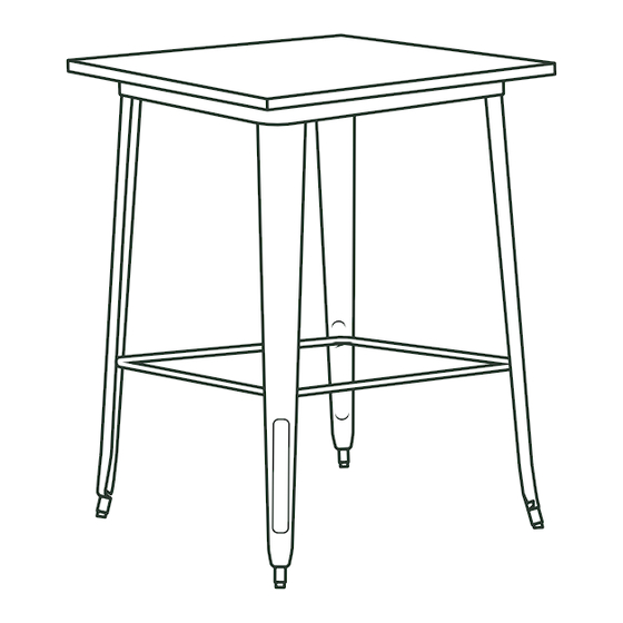
Bar Height Table
A S S E M B LY I N S T R U C T I O N S
ALLOY
Series
PA R T S L I S T
Table Top
A
Support Bar
B
S T E P 1
Place table top (A) upside down on a flat, clean surface.
Attach one table leg (C) to the corner of the table top. Hold the leg
against the corner and find the four threaded holes on the table top.
Use (4) M6x12 screws (E) to secure the leg to the table top using the
provided allen key (D).
B A R H E I G H T TA B L E • A S S E M B LY I N S T R U C T I O N S
(4) Table Legs
C
•
•
•
S T E P 2
Repeat the previous step for the remaining three legs. Do not
fully tighten screws yet.
H A R D WA R E
M6 Allen Key
(16) M6x12 Screws
D
E
N O T E S
Inspect all pieces for damage before assembly. Do not assemble
if any pieces are broken or damaged. Ensure you have all
required pieces before assembly.
Power drill is optional for assembly.
Graphics of images are shown with a square table top, but
assembly is the same for all table top shapes (rectangular,
square, and round).
W W W . L A N C A S T E R TA B L E A N D S E A T I N G . C O M
(4) M6x25 Screws
F
Advertisement

Related Manuals for Lancaster ALLOY Series


Summary of Contents for Lancaster ALLOY Series
- Page 1 Bar Height Table A S S E M B LY I N S T R U C T I O N S ALLOY Series PA R T S L I S T H A R D WA R E M6 Allen Key (16) M6x12 Screws (4) M6x25 Screws Table Top...
- Page 2 Bar Height Table A S S E M B LY I N S T R U C T I O N S ALLOY Series S T E P 3 S T E P 4 Place support bar (B) between all four legs. Locate the four holes Fully tighten all 16 screws on the table top and table legs.
Need help?
Do you have a question about the ALLOY Series and is the answer not in the manual?
Questions and answers