Table of Contents
Advertisement
Quick Links
Advertisement
Table of Contents

Subscribe to Our Youtube Channel
Related Manuals for AJ Aircraft AJ 103" Slick 540


Summary of Contents for AJ Aircraft AJ 103" Slick 540
- Page 1 AJ 103” Slick 540 Assembly Instructions aj-aircraft.com P a g e...
-
Page 2: Safety Precautions And Warnings
R/C flight as you Up Your Game with AJ Aircraft!! Safety Precautions and Warnings All of AJ Aircraft’s airframes have gone through many stages of extensive testing to ensure a high-quality kit which results in a safe and reliable airframe when assembled properly. Poor assembly practices along with substandard equipment will lead to an unsafe model. -
Page 3: Table Of Contents
Table of Contents Safety Precautions and Warnings ......................2 Description ............................4 Specs ..............................5 What’s in the box ........................... 5 Recommended Items for Completion ....................6 Tools Needed ............................6 Optional Configurations ........................7 Inspection ............................. 7 Covering ..............................8 Landing Gear ............................ -
Page 4: Description
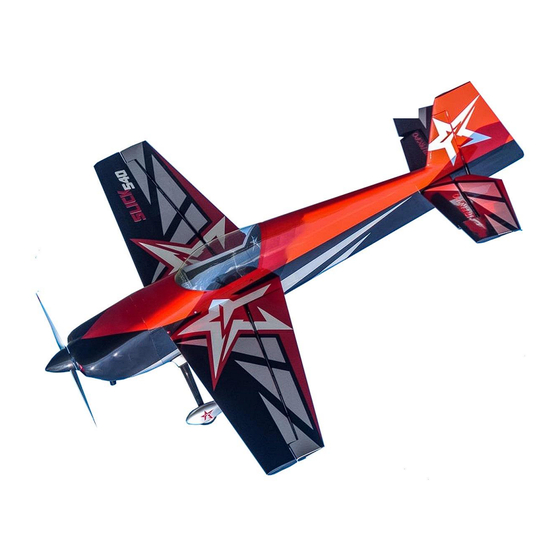
Description Whether you're looking to go out and do some 3d huckin' or lay down a smooth-as-butter precision flight, this airplane is for you! The wings have been thoroughly refined to allow precision flying, while not sacrificing any 3d characteristics. With a generous fuselage height, the model flies as well on its side as it does upright. -
Page 5: Specs
Specs • Wing Span - 103" • Length - 100" • Height - 27" • Wing Area – 1904 sq. in. • AUW (dry) - 26-27 lbs. • Gas Power - 100cc to 120cc • Radio - 9 channel with 8 high torque servos (400 oz./in minimum) & 1 throttle servo •... -
Page 6: Recommended Items For Completion
(2) x1.75” for push/pull • 9+ Channel Full Range Receiver • Ignition Spark Switch or Optical Kill Switch o or AJ Aircraft IBEC HV • Servo extensions: o (4) x 6” for receiver to wing o (2) x 6” for inner ailerons o (2) x 24”... -
Page 7: Optional Configurations
Optional Configurations You have the option of using a pull-pull rudder servo or a push-pull rudder servo setup. Fasteners, control horns and servo connecting rods are provided for optional rudder setups. Inspection We believe we offer the highest quality kits available. However you may find some minor blemishes, fractures or joint separations in the construction of our models. -
Page 8: Covering
Using an iron sock will reduce scratches. Red/White/Blue Scheme: • AJ Aircraft Covering (White) AJAC 2M W • AJ Aircraft Covering (Dark Blue) AJAC 2M DB • AJ Aircraft Covering (TRU Red) AJAC 2M TR •... -
Page 9: Landing Gear
The filler block can be held in position with strips of Landing Gear covering material, packing tape, or it can be glued in Landing gear parts contents are shown below. place. Install the landing gear with the thicker portion of the airfoil to the front. - Page 10 Install a wheel on the axel using a Nylock nut to retain the wheel. Install the wheel and axle onto the landing gear using Nylock nut. Test fit the wheel and wheel pants. Make sure the wheelpant has ample clearance around the tire. Trim the inside edge of the wheel pant as needed.
-
Page 11: Control Horn Installation
Mount the wheel pants to the landing gear with a Control Horn Installation washer and socket head screw. We recommend If not already opened -- using a thread locker on these screws. Carefully locate the servo pockets and aileron control horn mounting slots in the wings. - Page 12 Use sandpaper to roughen the lower portion of the Assemble a ball link (without a flange) to the control control horns on both sides. Roughen one side of horns using a socket head screw, washer and nylon the base plate. This will help the epoxy bond to the lock nut.
- Page 13 Apply epoxy to the control horn assembly and insert it into the aileron slots. Remove the control horn leaving the tape in position. Using a new hobby knife blade lightly cut through the covering but not into the balsa sheeting. Cut inside the tape edge about 1/16”.
-
Page 14: Aileron Servo Installation
Allow the epoxy to partially cure. Peel away the Connect a servo extension wire to the servo lead - masking tape after the epoxy is securely holding the 24” extension for the outer servo, 6” extension for control horn in place and still soft enough to easily the inner servo. - Page 15 Assemble the connection rod to a servo ball link This will make the measurement from the hinge line with the flange. Then connect the connection rod to to the linkage connection on the aileron horns as the control rod ball link. Make note that one end is a equal as possible.
-
Page 16: Elevator Assembly
mounting screws. (Socket head screws or a magnet Elevator Assembly attached to your screw driver may make inserting Connect the elevator servos to a receiver and power screws a little easier.) supply. Turn on your transmitter and set trim and sub trim to zero. -
Page 17: Rudder Assembly
Check the length of the assembly with the servo to estimate the length. When you get close to the correct length connect the flanged ball link to the servo arm with a washer and socket head screw. (Always adjust the connecting rod length with the servo powered up and centered.) Rudder Assembly You have the option of using a pull-pull rudder servo... - Page 18 Carefully locate the rudder control horn mounting slots. Use a covering iron to secure the covering around these areas before trimming away the covering. Cut the rudder covering to expose the control horn slots on both sides of the rudder. Remove the control horn and base.
- Page 19 centerline to locate two holes to connect the control horn. Mark the center of the rudder along the hinge line. Locate the control horn position by measuring from the center point to the control horn holes. Test fit to the rudder making sure the control horn is centered and square to the rudder.
-
Page 20: Pull-Pull Rudder Control
Slide the control horns into position and apply epoxy to the opposite site to adhere the other base in position. Assemble the alignment fixture with the control horn and rudder making sure the control horns are square to the rudder centerline. Wipe away excess epoxy using a paper towel soaked with denatured alcohol. - Page 21 Loop around the crush sleeve and back through the Connect the ball links to the rudder servo control sleeve again. Slide the second sleeve over the tail. horn using a screw, nylon lock nut and a washer. Pull the slack out of the cables and make sure the cables cross once inside the fuselage.
-
Page 22: Push-Pull Rudder Control
Center the rudder and position it aligned to the Mount the servo with the output shaft towards the nose of the airplane. Install the rudder control horn vertical stabilizer. Tape the rudder to the vertical as shown above for the rudder pull-pull setup. Use stabilizer to hold it centered. -
Page 23: Gas Engine Installation
The engine should be mounted with bolts through Gas Engine Installation the engine mounting plate, spacer(s), the fire wall, Plan your engine mounting by determining the through another flat washer, then a nylon lock nut. length of the engine, standoff, spacers or washers needed. - Page 24 Or you may have to mount the servo inside the fuselage and drill a pass-thru hole in the firewall to connect to the throttle arm. Depending on the orientation of the engine’s throttle arm, you may have to either use the throttle servo pocket on the bottom side of the engine box for twin cylinder engines.
-
Page 25: Ignition Module
Ignition Module It’s typically convenient to mount the engines ignition to the side or top of the engine box. Be sure to secure the spark plug wires so they don’t move around during flight. Excess movement can cause connector issues in time. Can also be mounted inside the engine box and pass the spark plug and sensor wiring through the pre- installed rubber grommets on the sides of the... -
Page 26: Standard In-Cowl Muffler Installation
Standard In-Cowl Muffler installation Canister Muffler installation Standard mufflers can be installed using the bolts Cut the covering away from the cannister ‘vent area’ and gaskets supplied with the engine or muffler. Be on the underside of the fuselage. mindful of the offset in the muffler mounting flanges as there is a left and right muffler. - Page 27 The kit comes with mounting brackets for different sizes of exhaust canisters. Select the appropriate bracket for your equipment. Adjust the height of the rear bracket to align the muffler to the header as straight as possible. Assemble the exhaust canister with header using the coupling and clamps.
-
Page 28: Fuel Tank
1” strap if you intend to do high G, 3D maneuvers. Fuel Tank We suggest using a quality 32 oz (1000cc) fuel tank and fuel line suited for gasoline such as AJ Aircraft, Fourtitude, Dubro, or Sullivan. The fuel tank vent line should loop up over the tank then exit through the bottom of the airplane. - Page 29 With the mufflers removed, fold the pattern down, install the cowl, fold the pattern back up to contact the bottom of the cowl and trace the hole patterns onto the cowl. Remove the cowl and cut out the exhaust tube holes.
-
Page 30: Wings And Horizontal Stabilizer Mounting
Install the cowl, remember to pass the choke linkage though the cowl. Wings and Horizontal Stabilizer mounting The wings and stabilizer/elevators are held in place with Quick Release slides. Wings – The Quick Release slides lock in the ‘Down’ position. To move them upward pull on the thumbscrew and to disengage the lock, and then slide the release upward. -
Page 31: Cg & Setup
Slide the wing tube through the fuselage. CG & Setup Take the time to properly balance and trim your With the Quick Release slides in the ‘Up’ position, aircraft. slide a wing onto the wing tube. Plug in the aileron extensions per your installation. - Page 32 CG should nearly hold the up-line. And a tail heavy CG will steepen the up-line. Enjoy your new plane! We at AJ Aircraft sincerely hope you enjoy flying the 103” Slick. Feel free to create a support ticket at aj-aircraft.com if you have any problems, questions, or suggestions.
Need help?
Do you have a question about the AJ 103" Slick 540 and is the answer not in the manual?
Questions and answers
I have 4 control horns 1 size, and 6 control horns a different size. Where do the 4 go in the wing or the elevator?