Table of Contents
Advertisement
Quick Links
Advertisement
Table of Contents

Related Manuals for AJ Aircraft 2M AJ Acuity


Summary of Contents for AJ Aircraft 2M AJ Acuity
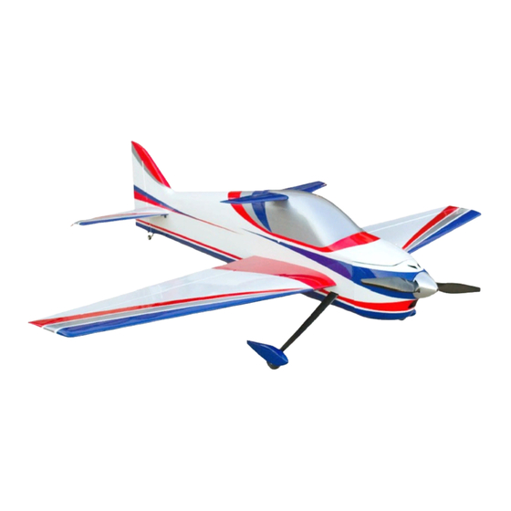
- Page 1 2M AJ Acuity Assembly Instructions...
- Page 2 WARNING AJ Aircraft’s extensive testing ensures a high quality kit that has gone through many stages to provide you with a safe, reliable, airframe. Poor assembly will lead to an unsafe model and therefore the instructions must be followed closely.
-
Page 3: Table Of Contents
Contents Contents ....................................2 Features ....................................2 Optional Configurations ................................3 Recommended Items for Completion ............................. 3 Tools Needed ..................................3 Covering ....................................4 Wings ...................................... 5 Landing Gear ................................... 9 Fuselage ....................................11 Rudder ....................................11 Push-Pull Rudder Control ..............................11 Pull-Pull Rudder Control .............................. -
Page 4: Optional Configurations
You have the option of using a pull-pull rudder servo or a push-pull rudder servo setup. Fasteners, control horns and servo connecting rods are provided for optional rudder setups. Recommended Items for Completion AJ Aircraft AJ5230-20P/205KV 12S 20x13 2 blade prop or 19.5x13 3 blade prop ... -
Page 5: Covering
Covering The covering on your Laser may have developed loose areas through temperature and humidity changes between manufacturing and shipping. This may also occur during the summer heat. The covering may require retightening a few times during your first summer of flying. Take a few minutes to go over all of the seams making sure all edges are secure. -
Page 6: Wings
Wings Carefully locate the aileron servo pocket. Shining a light through opposite side of the wing will help highlight the pocket location. The pocket is about 10” (255mm) from the wing root. Use a new hobby knife blade to cut though the covering. The hinges should already be glued into the ailerons. - Page 7 Slip each of the aileron hinges into the wing. Align the Check the aileron position at the hinges and wing tip end of the aileron to the wing tip. again before gluing. Start with the hinge near the wing tip. Flex the aileron slightly and apply a few drops of thin CA glue to one side.
- Page 8 Use sand paper to roughen the lower portion of the Apply epoxy to the slot in the aileron. Use a pin to help control horns on both sides. This will help the epoxy push the epoxy in. bond to the control horn parts. Test fit the control horn in the slot.
- Page 9 With the servo installed mark the mounting hole Attach the servo wire to the installation string and gently locations. Pre-drill for servo mounting screws using a pull the wire through the wing as you insert the servo 1/16” drill. Install the servo with the wood screws that into the wing.
-
Page 10: Landing Gear
The landing gear screws are supplied installed in the fuselage. Remove the 6, M4 socket head screws. Carefully locate the landing gear slot in the side of the fuselage just below the leading edge of the wing location. Make a cut in the center of the slot and at the corners. Use your trim iron to fold and attach the covering into the slot. - Page 11 Use 6 flat washers from the landing gear parts bag with Insert the wheel and axel into the wheel pant, then into the screws removed earlier to attach the landing gear. landing gear. Align the wheel pant indentation with the Add a drop of removable thread locker to the screws landing gear.
-
Page 12: Fuselage
Fuselage There is a servo pocket on each side of the fuselage. This pocket is intended for a push pull rudder setup. If you Inspect the fuselage for any interior joints that may have plan to use a pull-pull cable setup DO NOT cut the loosened as a result of shipping &... -
Page 13: Pull-Pull Rudder Control
Remove the rudder by sliding out the hinge pin. Trim the Tests fit the control horns to the slots. Use a file to covering from the control horn slot and follow the same modify the slot as needed. The control horn should be installation process used for ailerons. - Page 14 Connect the servo to a receiver and power supply. Turn Tread the brass cable eyes about half way into the ball on your transmitter. Set trim and sub trim to zero. Install links. a servo arm on the servo about perpendicular to the servo’s side.
-
Page 15: Elevator
Elevator Pull the slack out of the cables and make sure the cables cross once inside the fuselage. Connect the ball links to The elevators are pre-hinged but are not glued. the rudder control horn. Use a hole spacing that closely Slip each of the aileron hinges into the wing. - Page 16 The horizontal stabilizer will hold a 15x33x27mm servo with 4 mounting screws such as the Futaba BLS173VS. (Some filing to adjust the servo slot may be needed.) Add a few drops of thin CA glue around the mounting holes to harden the wood. Thread 2 ball links onto a turnbuckle connecting rod.
-
Page 17: Electric Motor
Slide the carbor fiber horizontal stabilizer tube thought When using the AJ 5230-20P-205KV motor standoffs are the fuselage. Then slide on the horizontal stabilizer. not needed. However you will need to use the 5mm shaft spacer that comes with the motor. Bolt the motor directly to the firewall using 4mm socket head cap screws and flat washers. -
Page 18: Cowl & Canopy
Cowl & Canopy Drill a 1/16” hole in the side of the cowl at the locations marked in the previous step. Do not drill through the The cowl will be mounted using 4 wood screws through wood tab on the fuselage. side of the fuselage just in front of the firewall. - Page 19 There are 2 areas in the bottom of the fuselage below the Measuring from both sides center the T-Canaliser in the rudder servo that can be cut open to provide air flow for canopy. motor and speed controller cooling. Use a covering iron to seal the edges of the areas.
-
Page 20: Radio Installation & Setup
Radio Installation & Setup The final step for assembly is attaching the wings. Your receiver can be mounted anywhere in the airframe. Heat the area around the large slot to attach the A piece of foam rubber should be used between the covering. - Page 21 Enjoy your new plane! We at AJ Aircraft sincerely hope you enjoy flying the 2M AJ Acuity. Feel free to create a support ticket at aj-aircraft.com if you have any problems, questions, or suggestions. Once you get a few flights in, we would greatly appreciate your review...
Need help?
Do you have a question about the 2M AJ Acuity and is the answer not in the manual?
Questions and answers