Table of Contents
Advertisement
Quick Links
Advertisement
Table of Contents

Subscribe to Our Youtube Channel
Related Manuals for AJ Aircraft Raven 73"


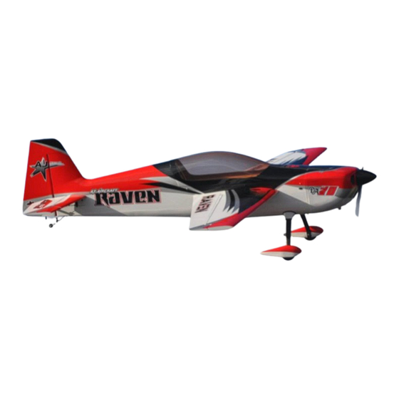
Summary of Contents for AJ Aircraft Raven 73"
- Page 1 73” AJ Raven Assembly Instructions...
-
Page 2: Congratulations
Building the airplane is very straight forward. The rudder cables are pre-installed, and the hinges are pre- glued. AJ Aircraft goes the extra step to make it easy to get this bird in the air in no time flat. High quality parts including dual G10 fiberglass control horns, carbon fiber wing tubes and heavy duty ball-links and turnbuckles ensure you won't need to spend more money replacing cheap hardware. -
Page 3: Table Of Contents
WARNING! AJ Aircraft’s extensive testing ensures a high quality kit that has gone through many stages to provide you with a safe, reliable, airframe. Poor assembly will lead to an unsafe model and therefore the instructions must be followed closely. Should you have any questions, please do not hesitate to contact us. The safe operation of this model is your responsibility and yours alone. -
Page 4: Features
Before starting, read through the entire set of instructions to familiarize yourself with the process. If there’s ever a question, contact AJ Aircraft. 734-244-4015 Features Specs: What's in the box: • • Wing Span - 73" NEW - Carbon-Kevlar plywood construction! •... -
Page 5: Recommended Items For Completion
Recommended Items for Completion • Power System AJ flies this airframe with the Electric Motor (If you choose to go electric.) following equipment: ▪ 2400+ Watt 8S/12S or Equivalent ▪ 100-120 Amp ECS AJ5230-20P/205KV 12S ▪ 12” ESC (Servo) Wire Extensions Falcon 20x10 prop ▪... -
Page 6: Tools Needed
Tools Needed Blue Painters Masking Tape Small Flat File Thin CA Glue Small Round File 30 Minute Epoxy or Electric Drill w/ Assorted Small Bits Polyurethane Glue (Gorilla Glue) Small Flat Blade Screwdrivers Denatured Alcohol Small Phillips Screwdriver Paper Towels Sandpaper (150-220 Grit) Removable Thread Locker (Loctite 242, Blue) Needle Nose Pliers... -
Page 7: Inspection
Inspection We believe we offer the highest quality kits available. However, you may find some minor blemishes, fractures or joint separations in the construction of our models. Many of these can be easily repaired by backing up the joint with balsa sheet or hard balsa sticks without affecting the performance or appearance of the aircraft. -
Page 8: Wings
Carefully locate the aileron control horn slots. Use a Wings covering sealing iron to bond the covering in the area the control horn will sit. Trim the covering away to expose The ailerons are pre hinged and glued to the wing. Firmly the slots. - Page 9 With the control horn in position apply painter’s masking Use sand paper to roughen the lower portion of the tape around the control horn base. Put the tape up to control horns on both sides. Roughen one side of the the base edge.
- Page 10 Wipe away excess epoxy using a paper towel soaked with Attach the servo wire to the installation string and gently denatured alcohol. Use an upward rolling motion as you pull the wire through the wing as you insert the servo wipe the excess epoxy to lift it from the surface.
-
Page 11: Landing Gear
Connect the connecting rod to the servo control arm and the aileron control horn using 2mm machine screws, locking nuts and a flat washer at the servo control arm. (Turn on the transmitter, receiver and servo while making adjusting to the connecting rod. This will keep the servo in its correct position.) Landing Gear Adjust the position of the aileron to the wing by turning... - Page 12 Drill pilot holes in the wheel pants for wood screws. Drill through the holes in the landing gear and through to the inside of the wheel pant. Place the wood filler block over the landing gear. We suggest using a piece of white covering or clear packing tape to hold the filler block in position.
-
Page 13: Fuselage
Ensure all set screws are tight on the pre-assembled tail Carefully locate the horizontal stabilizer pocket. Use a wheel assembly. trim iron to seal the covering around the edges of the pocket before trimming. Use a new hobby knife blade to cut though the covering. -
Page 14: Elevator
Install and center the main wing tube. Look at the plane Elevator from the back forward to make sure that the horizontal The hardware provided may be used to control elevator stabilizer is parallel with the wing tube. Notice that the halves with 1 or 2 servos. - Page 15 With the control horn in position apply painter’s masking Apply epoxy to the slots in the elevator. Use a pin to help tape around the control horn base. Put the tape up to push some epoxy into the slots. the base edge. Not under or over it. Apply epoxy to the control horn assembly and insert it Assemble a rod end to the control horn using a supplied into the elevator slots.
- Page 16 Roughen up the jointer plate for the elevator halves with Test fit pieces together and adjust as needed so you get a a piece of sand paper so the epoxy will adhere better. good fit between the elevator and the stabilizer. Check (The joiner plate is not used if you plan to use 2 elevator the hinge gap and the gap at the counter balance.
- Page 17 We suggest using 30 minute epoxy for the elevator Carefully remove “masking” tape before the epoxy fully jointer plate and polyurethane glue for the hinges. (Add sets. But do not remove the tape at the stabilizer and a drop of water to each hinge hole if using polyurethane elevator counter balance until epoxy is fully cured.
-
Page 18: Rudder
Install the servo into the fuselage and pre-drill for servo Use sand paper to roughen up the control horns so the mounting screws using a 1/16” drill. Install the servo with epoxy will adhere better. Assembly the control horns the wood screws that came with your servos. Remove with a ball link and brass cable eye. - Page 19 Align the rudder hinges to the vertical stabilizer hinges. Start the cable assembly at the servo end inside the Insert the rudder hinge pin through the top of the rudder fuselage. Thread on 2 crush sleeves and the brass cable then through each of the hinges.
-
Page 20: Electric Motor
Connect the ball links to the rudder control horn using a Remove the tape from the rudder/vertical stabilizer. socket head screw, nylon lock nut and a washer. Pull the Adjust the length of the cable by turning the brass cable slack out of the cables and make sure the cables cross eyes to center the rudder and achieve the desired cable once inside the fuselage. -
Page 21: Cowl & Canopy
Use an “X” mount with a mounting bolt circle of 75mm to Cowl & Canopy mount your motor. Use the 4mm bolts and washers. Apply painters’ tape over the mounting tabs to transfer Add removable thread locker during installation. the mounting locations to the cowl. Push a pin through the tape and hole in the mounting tab. - Page 22 Trim the covering in on the fuselage exposing the canopy Use nylon zip ties to secure the ESC to the bottom or side mounting holes. of the motor box. We recommend putting a small piece of foam between the ESC and motor box to dampen vibrations.
-
Page 23: Gas Engine
The distance between the prop backer plate and the Gas Engine firewall should be 160-161mm. This will provide space Many of the following pictures are of the 73” AJ Laser between the spinner and the cowl. with is very similar in construction to the Raven. The firewall is marked with the centerline offset to account for the built-in thrust angle and drilled with a 70mm wide x 55mm hole pattern. - Page 24 The placement of the throttle servo is dependent on the engine you choose to use. The servo can be mounted in the front of the fuselage in many cases. (If you choose this location drill 5 holes through the top of the engine box so servo mounting screws and the servo arm screws can be accessed.) Cut the cowl as needed to clear the engine head, spark...
- Page 25 We suggest using a quality 16 oz (500cc) fuel tank suited The fuel tank vent line should loop up over the tank then for gasoline such as Fourtitude, Dubro, or Sullivan. Begin exit through the bottom of the airplane. The fill line assembly by bending the longest copper tube as a vent should be capped by a fuel dot.
-
Page 26: Radio Installation & Setup
1" in front of the wing tube (+/- 1/2") Enjoy your new plane! We at AJ Aircraft sincerely hope you enjoy flying the Raven. Feel free to create a support ticket at aj-aircraft.com if you have any problems, questions, or suggestions.
Need help?
Do you have a question about the Raven 73" and is the answer not in the manual?
Questions and answers