
Related Manuals for EnerSys iQ Mini


Summary of Contents for EnerSys iQ Mini
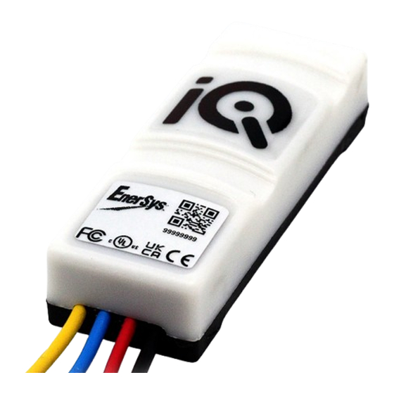
- Page 1 Battery Monitoring Device OWNER’S MANUAL Model Numbers: 300Q, 300B8, 310Q, 310S, and 301Q UL Listing applies to certain models only. www.enersys.com...
-
Page 2: Table Of Contents
CONTENTS Introduction ..........3 Features ............4 Technical Specifications ......4 Dimensions ..........5 Installation ..........6 300Q ............6 300B8 ............10 310Q ............14 310S ............19 301Q ............24 Visual LED Indication ......... 28 Connectivity ..........29 Frequently Asked Questions (FAQs).. -
Page 3: Introduction
This owner’s manual is not intended to substitute for any training on handling and operating the iQ Mini™ battery monitoring device that may be required by local laws and/or industry standards. Proper instruction and training of all users must be ensured prior to any contact with the battery system. -
Page 4: Features And Specifications
FEATURES & SPECIFICATIONS Features • Real time status • iQ Mini™ battery monitoring device mode status • Low voltage alert indicators • iQ Mini™ battery monitoring device can be • Multiple connection types installed on multiple battery types • Small and slim fit •... -
Page 5: Dimensions
DIMENSIONS Dimensions IQ mini™ Battery Monitoring Device Overall Dimensions Figure 1: iQ Mini™ Battery Monitoring Device Dimensions 29 mm (1.14") 20 mm (0.79") 80 mm (3.15") Figure 1 80 mm (3.15") 29 mm (1.14") 20 mm (0.79") *All dimensions are given in mm (inch). -
Page 6: Installation
INSTALLATION Installation: Model No. 300Q The iQ Mini™ battery monitoring device - 300Q is a battery life monitor that provides real-time status and is intended for use on 12V to 80V TPPL batteries. The iQ Mini™ battery monitoring device monitors and records cycles, temperatures, and automatically sends this data to a gateway or app for visualisation online. - Page 7 INSTALLATION Installation: Model No. 300Q (cont.) Tools required Sample cells layout Figure 2: iQ Mini™ Battery Monitoring Device Final Assembly on 24V TPPL Batteries Figure 2 iQ Mini™ Battery Monitoring Device - 300Q Connection - Q...
- Page 8 INSTALLATION Installation: Model No. 300Q (cont.) Ensure the voltage is between 2.0 and 2.25 volts Attach the iQ Mini™ Battery Monitoring Device to per cell before installation. the top of the battery. Connect the red cable to the positive terminal.
- Page 9 INSTALLATION Installation: Model No. 300Q (cont.) Connect the black cable to the negative terminal. Once the power has been connected, check the following start-up LED sequence. The black cable must be connected last. LED Check | Stage ONE Voltage Check | Stage TWO = 12v = 24v = 36v...
-
Page 10: 300B8
INSTALLATION Installation: Model No. 300B8 The iQ Mini™ battery monitoring device - 300B8 is a battery life monitor that provides real-time status and is intended for use on 12V to 80V TPPL batteries. The iQ Mini™ battery monitoring device monitors and records cycles, temperatures, and automatically sends this data to a gateway or app for visualisation online. - Page 11 INSTALLATION Installation: Model No. 300B8 (cont.) Tools required Sample cells layout Figure 3: iQ Mini™ Battery Monitoring Device Final Assembly on 24V TPPL Batteries Figure 3 iQ Mini™ Battery Monitoring Device - 300B8 Connection - B8...
- Page 12 INSTALLATION Installation: Model No. 300B8 (cont.) Ensure the voltage is between 2.0 and 2.25 volts Attach the iQ Mini™ battery monitoring device to per cell before installation. the top of the battery. Connect the red cable to the positive terminal.
- Page 13 INSTALLATION Installation: Model No. 300B8 (cont.) Connect the yellow cable to 12V/24V from the Connect the black cable to the negative terminal. negative terminal. The black cable must be connected last. (*N.B. Only connect at 24V for 80V batteries) LED Check | Stage ONE Once the power has been connected, check the 1 green >...
-
Page 14: 310Q
INSTALLATION Installation: Model No. 310Q The iQ Mini™ battery monitoring device - 310Q is a battery life monitor that provides real-time status and is intended for use on 12V to 80V flooded batteries. The iQ Mini™ battery monitoring device monitors and records cycles, temperatures, and automatically sends this data to a gateway or app for visualisation online. - Page 15 INSTALLATION Installation: Model No. 310Q (cont.) Tools required 1/2” Sample cells layout Figure 4: iQ Mini™ Battery Monitoring Device Final Assembly on 48V Flooded Batteries Figure 4 iQ Mini™ Battery Connection - Q Electrolyte Probe Monitoring Device - 310Q...
- Page 16 INSTALLATION Installation: Model No. 310Q (cont.) Ensure the voltage is between 2.0 and 2.25 volts Attach the iQ Mini™ battery monitoring device to per cell before installation. the battery and secure it with cable ties. Install the electrolyte probe. Punch a hole.
- Page 17 INSTALLATION Installation: Model No. 310Q (cont.) Minimum 3-5mm (1/8”) Trim the probe to the correct length and place it Make sure the probe is at least 3–5 mm (1/8 inch) into the battery. above the plate. Connect the red cable to the positive terminal. Insert the FlexiTap into the centre of the cable to ensure a good connection.
- Page 18 INSTALLATION Installation: Model No. 310Q (cont.) LED Check | Stage ONE Connect the black cable to the negative terminal. 1 green > 1 red > 1 amber & 1 blue Once the power has been connected, check the This flashing pattern will repeat twice before the following start-up LED sequence.
-
Page 19: 310S
INSTALLATION Installation: Model No. 310S The iQ Mini™ battery monitoring device - 310S is a battery life monitor that provides real-time status and is intended for use on 12V to 80V flooded batteries. The iQ Mini™ battery monitoring device monitors and records cycles, temperatures, and automatically sends this data to a gateway or app for visualisation online. - Page 20 INSTALLATION Installation: Model No. 310S (cont.) EPOXY Tools required 1/2” Sample cells layout Figure 5: iQ Mini™ Battery Monitoring Device Final Assembly on 48V Flooded Batteries Figure 5 iQ Mini™ Battery Connection - S Electrolyte Probe Monitoring Device - 310S...
- Page 21 INSTALLATION Installation: Model No. 310S (cont.) Ensure the voltage is between 2.0 and 2.25 volts Attach the iQ Mini™ battery monitoring device to per cell before installation. the battery and secure it with cable ties. Install the electrolyte probe. Punch a hole.
- Page 22 INSTALLATION Installation: Model No. 310S (cont.) Minimum 3-5mm (1/8”) Trim the probe to the correct length and place it Make sure the probe is at least 3–5mm (1/8 inch) into the battery. above the plate. Connect the red cable to the positive terminal. Screw the M4 connection to the terminal.
- Page 23 INSTALLATION Installation: Model No. 310S (cont.) Connect the yellow cable to 12V/24V from the Connect the black cable to the negative terminal. negative terminal. The black cable must be connected last. NOTE: Only connect at 24V for 80V batteries. LED Check | Stage ONE Once the power has been connected, check the 1 green >...
-
Page 24: 301Q
INSTALLATION Installation: Model No. 301Q The iQ Mini™ battery monitoring device - 301Q is a battery life monitor that provides real-time status and is intended for use on 12V to 80V TPPL batteries. The iQ Mini™ battery monitoring device monitors and records cycles, temperatures, and automatically sends this data to a gateway or app for visualisation online. - Page 25 INSTALLATION Installation: Model No. 301Q (cont.) Tools required Sample cells layout Figure 6: iQ Mini™ Battery Monitoring Device Final Assembly on 48V TPPL Batteries Figure 6 iQ Mini™ Battery Connection - Q Temperature Sensor Probe Monitoring Device - 301Q...
- Page 26 INSTALLATION Installation: Model No. 301Q (cont.) Ensure the voltage is between 2.0 and 2.25 volts Attach the iQ Mini™ battery monitoring device to per cell before installation. the battery and secure it with cable ties. Install the temperature sensor probe.
- Page 27 INSTALLATION Installation: Model No. 301Q (cont.) Connect the yellow cable to 12V/24V from the Connect the black cable to the negative terminal. negative terminal. The black cable must be connected last. (*N.B. Only connect at 24V for 80V batteries) LED Check | Stage ONE Once the power has been connected, check the 1 green >...
-
Page 28: Visual Led Indication
2.0 and 2.25 vpc during is indicated by the green LED flash just after the installation. initial boot-up sequence. Refer to the table below for the voltage detected by the iQ Mini™ battery monitoring device. Tap Connection Number of Flashes... -
Page 29: Connectivity
Connectivity iQ gateway™ Battery Data Transmitter The iQ GATEway™ battery data transmitter automatically collects the data from any iQ Mini™ battery monitoring devices that are within range and uploads the data directly to the online portal. This data is available in real time and shows the status of the connected devices. - Page 30 CONNECTIVITY Connectivity (cont.) Tools required iQ GATEway™ BATTERY DATA TRANSMITTER Overall Dimensions Figure106: iQ GATEway™ Battery Data Transmitter Dimensions 171 mm (6.73") 161.35 mm (6.35") 142.35 mm (5.6") 201 mm (7 .91") 80 mm (3.15") 158 mm (6.22") 122.36 mm (4.82") *All dimensions are given in mm (inch).
- Page 31 CONNECTIVITY Connectivity (cont.) Min 1m distance between antennae IQ-GATE-01 IQ-GATE-01 SN 123434 SN 123434 MAC AB: 12: 13: 44: aE MAC AB: 12: 13: 44: aE GATEway GATEway Power Signal Power Uplink Signal Data Uplink Fault Data Fault Place both antennae as high as possible to Powering the device.
-
Page 32: Frequently Asked Questions (Faqs)
® There is a rapid flashing amber LED on the iQ Mini™ battery monitoring device – what does this mean? The flashing amber means the voltage range is not correct. Ensure that the red and black wires are connected across 12V, 18V, or 24V only. -
Page 33: Spare Parts
® I’ve powered up the gateway, but none of the LEDs are turning on. Check the plug is correctly connected and turned on. If the problem persists contact your local EnerSys ® service location. The blue LED is not flashing – what does this mean? This means the receiver has not been activated and data is not being uploaded. - Page 34 SPARE PARTS Spare Parts (cont.) Terminal Connection B8 - Bolt Part no. Parts 300mm (11.81") IQ-RFB8 Terminal Connection M8 Bolt 300mm (11.81") 300mm (11.81") Terminal Connection S - M4 Screw Part no. Parts 300mm (11.81") IQ-RFS Terminal Connection M4 Screw 300mm (11.81") 300mm (11.81") iQ GATEway™...
- Page 35 NOTES Notes...
- Page 36 © 2024 EnerSys. All rights reserved. Unauthorised distribution prohibited. Trademarks and logos are the property of EnerSys and its affiliates except UL, CE, UKCA, IEC, Android, and iOS, which are not the property of EnerSys. Subject to revisions without prior notice. E.&O.E.
Need help?
Do you have a question about the iQ Mini and is the answer not in the manual?
Questions and answers