Table of Contents
Advertisement
Quick Links
Advertisement
Table of Contents

Related Manuals for Maxent MX-50X2


Summary of Contents for Maxent MX-50X2
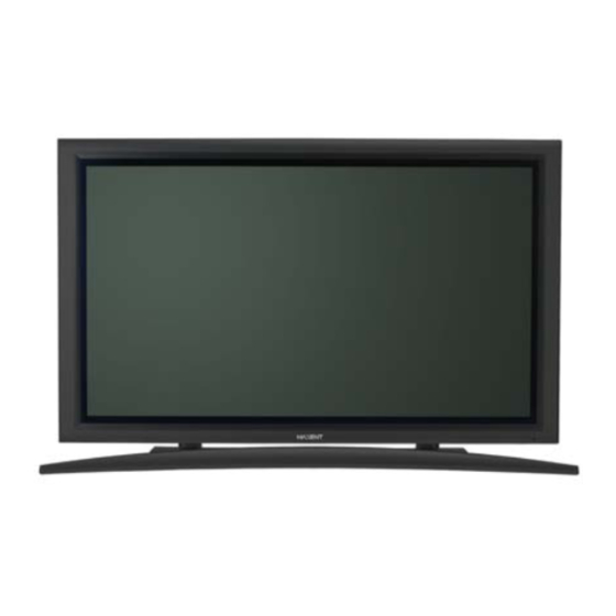
- Page 1 50” PDP Monitor Owners Manual...
-
Page 2: Important Safety Instructions
Important Safety Instructions WARNING RISK OF ELECTRIC SHOCK DO NOT OPEN WARNING: To reduce the risk of electric shock, do not remove the front or back covers. No user-serviceable parts inside. Refer servicing to qualified service personnel only. The lightning flash with arrow-head The exclamation point within a triangle within a triangle is intended to inform is intended to tell the user that important... -
Page 3: Cleaning & Maintenance
Important Safety Instructions If an outdoor antenna or cable system is connected to the display, be sure the antenna or cable system is grounded to provide some protection against voltage surges and static charge buildups. Section 810 of the National Electrical Code, ANSI/NFPA No.70-1984, provides information about proper grounding of the mast and supporting structure, grounding of the lead-in wire to an antenna discharge unit, size of grounding conductors, location of antenna discharge unit, connection to grounding electrodes, and requirements for the grounding electrode. -
Page 4: Regulatory Notice
Regulatory Notice FCC Statement The Federal Communications Commission Radio Frequency Interference Statement includes the following warning: This equipment has been tested and found to comply with the limits for a Class B digital device, pursuant to Part 15 of the FCC Rules. These limits are designed to provide reasonable protection against harmful interference in a residential installation. -
Page 5: Table Of Contents
Table of Contents Important Safety Instructions ........................2 Special Notices ..........................2 Warnings & Precautions ........................2 Cleaning & Maintenance ........................3 Special Warranty Info ........................3 Regulatory Notice ............................ 4 Getting to Know Your Display ........................7 Package Contents ..........................8 Front Panel Controls ......................... - Page 6 Table of Contents Memorizing Channels ........................58 On-Screen Status Display (TV Mode) ....................60 Blue Back ............................61 Changing Channels ........................... 61 MTS ..............................62 Closed Captioning ..........................63 V-Chip ............................... 64 Favorite Channel Programming ......................67 Quick View ............................68 Channel Lock ............................
-
Page 7: Getting To Know Your Display
Flat Panel Monitor Getting to Know Your Display... -
Page 8: Package Contents
Getting to Know Your Display Package Contents Flat Panel Display Remote Control Batteries 50" PDP Monitor User Manual Warranty Card AC Power Cord... -
Page 9: Front Panel Controls
Getting to Know Your Display Front Panel Controls Status LED Volume Adjustment Buttons Not Illuminated - No AC Power detected Use these buttons to adjust volume up and down. These keys also serve as navigation and adjust- If the main power switch (rear of panel) is turned off, ment keys when On Screen Display menu is this LED will not illuminate. -
Page 10: Rear Panel Connections
Getting to Know Your Display Rear Panel Connections RS-232 DVI IN Composite / S-Video Inputs Antenna Jack Connect Composite or S-Video signals from Connect to TV or CATV antenna. external sources such VCRs or DVD players. RGB Input Connect to RGB output of computer or Set-Top box. Component Video Inputs Auto-detecting component video inputs (Y/Pb/Pr or RS-232 Connector... -
Page 11: Remote Control
Getting to Know Your Display Remote Control Standby Power On/Off Push this button to turn on the monitor from Standby mode. Push it again to turn off to Standby mode. Number Keypad Use number keypad to select the TV channel you want to watch. -
Page 12: V-Chip
Getting to Know Your Display Remote Control (con’t) MTS Stereo Engages MTS stereo reception for TV. (See Page 62) Closed Captioning Turns on Closed Caption Mode. (See Page 63) Sub-Picture Channel UP/DOWN V-Chip Engages V-Chip protection circuitry settings. (See Page Smart ID This key is not applicable to this monitor. -
Page 13: Display Connections
Flat Panel Monitor Display Connections... -
Page 14: Connecting Tv Or Catv
Display Connections Connecting TV or CATV Connecting to TV or Cable TV Connect the RF cable from the antenna or cable socket to the RF connector labeled as TV on the back of the monitor. Connecting a VCR Using S-Video Input Connect the S-Video (4-pin DIN) connector from the VCR to the S-Video input on the back of monitor. -
Page 15: Connecting A Dvd
Display Connections Using TV Input Connect the output to TV (RF out or Antenna out) connector from the VCR to the TV input on the back of monitor. Notes: Cable must be connected from wall/cable box into the VCRs antenna (RF) input. Connecting a DVD Using Component Video Input There are two sets of component video inputs provided. -
Page 16: Using Composite Input
Display Connections Connecting a DVD (con’t) Using S-Video Input Connect the S-Video (4-pin DIN) connector from the DVD to the S-Video input on the back of monitor. Connect the red (R) and white (L) audio jacks from the DVD to the (R) and (L) audio-in jacks located next to the S-Video connector. -
Page 17: Connecting A Set-Top Box
Display Connections Connecting a Set-Top Box Using Component Video Input There are two sets of component video inputs provided. You can use either set of component inputs to connect your STB. Some HDTV Set top boxes may not have a Component Video output. Instead, use RGB input method. -
Page 18: External Audio Connections
Display Connections Connecting a Set-Top Box (con’t) Using DVI Input Connect the DVI-D connector from the back of the HDTV set top box to the DVI-IN Connector located on the back of the monitor. Connect the red (R) and white (L) audio-out jacks from the HDTV set top box to the R and L audio-in jacks located next to the DVI-D connector. -
Page 19: Connecting A Subwoofer
Display Connections Connecting a Subwoofer This monitor is equipped with a subwoofer output for connecting to an external amplified subwoofer. Connect a RCA cable from the subwoofer’s input to the subwoofer’s output jack on the back of the monitor. Notes: The RCA subwoofer outputs frequencies below 120Hz. -
Page 20: Setting Up Your Monitor Using Plug And Play
Display Connections Connecting a PC (con’t) Setting Up Your Monitor Using Plug and Play This monitor adheres to VESA Plug and Play standard to eliminate complicated and time consuming setup of monitors. This monitor identifies itself to the computer and automatically sends the PC its Extended Display Identification Data (EDID) using Display Data Channel (DDC) protocols. - Page 21 Display Connections Connecting a PC (con’t) Supported Resolutions This monitor supports the following resolutions Horizontal Vertical Frequency Frequency Dot Rate Vertical Horizontal Dot x Line (KHz) (Hz) (MHz) Polarity Polarity 640 x 480@60Hz 31.469 59.940 25.175 640 x 480@72Hz 37.861 72.809 31.500 640 x 480@75Hz...
-
Page 22: Rs-232 Connection
Display Connections RS-232 Connection Overview This monitor is equipped with an RS-232 serial terminal for using the monitor with computer controls. The RS-232 serial terminal conforms to the RS-232C interface specification. The computer will require software application (such as HyperTerminal) which allows the computer to send and receive control data that can support the communication parameters described in this section. - Page 23 Display Connections The following is an example of the communication process between the PC and the monitor using a program such as HyperTerminal. Example: Read Power Status followed by Power On command and input select to AV1 with disruption PC Status Monitor Status Send command to read power status Monitor rcv’s command...
- Page 24 Display Connections Description Command Data Options TV Channel Change 001…125 Closed Captioning OFF, CC1, CC2, CC3, CC4, TX1, TX2, TX3, TX4 Zoom WID=16:9, PAN=Panorama Stretch, NOR=4:3 with black bars, ZO1=Zoom1, ZO2=Zoom2 R-Gain 000…551 G-Gain 000…551 B-Gain 000…551 R-Bias 000…999 G-Bias 000…999 B-Bias 000…999...
-
Page 25: Basic Operations
Flat Panel Monitor Basic Operations... -
Page 26: Powering On/Off
Basic Operations Powering On/Off Using Front Panel or Remote Control Make sure the monitor is plugged into the wall outlet and the main AC switch located on the rear of the monitor is switched to ON position. If the power is plugged in and the AC switch is on, the STATUS LED will illuminate in orange color. -
Page 27: Volume Adjustment
Basic Operations Using Direct Input Selection Keys If you prefer not to cycle thru all available inputs, you can use the Direct Input Selection keys located towards the bottom of the remote control. Simply select the input that you would like to switch to and press the Direct Input Selection key for that input. -
Page 28: On-Screen Display Menu
Basic Operations On-Screen Display Menu Accessing OSD Menu via Remote Control or Front Panel The On-Screen Display (OSD) menu allows access to setup various parameters equipped with this display. To access the OSD menu, press button on the front panel of monitor or press any one of OSD Menu the four arrow keys located on the remote Navigation... -
Page 29: On-Screen Status Display
Basic Operations OSD Background Color Setting The background color of the OSD Menu can be customized. To change the OSD Background color setting, please follow the steps below. Access the OSD menu, select SETUP submenu. Use keys to highlight OSD BACKGROUND. -
Page 30: Understanding Widescreen Modes
Basic Operations Understanding Widescreen Modes This monitor is capable of displaying a widescreen image on the native 16:9 aspect ratio screen. However, not all available video content fits perfectly in a widescreen (16:9) format resulting in unused screen space. This monitor is capable of displaying images in various formats that is suitable for various types of content depending on its size. -
Page 31: Changing Aspect Ratios
Basic Operations Changing Aspect Ratios Using Remote Control All widescreen viewing modes are available by pressing the key. Pressing this key repeatedly will cycle through all six modes: Wide RGB/DVI mode Native (1:1) Note: Under Component video input mode, only 16:9 and 4:3 modes are available. - Page 32 Basic Operations...
-
Page 33: Picture Controls
Flat Panel Monitor Picture Controls... -
Page 34: Adjusting Picture Settings
Picture Controls Adjusting Picture Settings Using OSD Menu Various picture adjustments can be set using the Picture Adjustment OSD menu. Press the on the front panel or remote control. Use to select the PICTURE option from the menu and press key to confirm selection. - Page 35 Picture Controls BRIGHTNESS Adjust brightness to enhance the level of dark areas in the video picture such as night scenes and shadow scenes. Increasing brightness will make dark areas more visible. COLOR Use color to adjust the color saturation of the video picture. Increasing color will make the color more intense.
-
Page 36: Picture-In-Picture
Picture Controls Picture-in-Picture Turning On PIP PIP and POP modes allow users to view two video input sources simultaneously. Press the key once on the remote control to engage in Picture-in-Picture mode. Pressing the key repeatedly will cycle thru the following modes: PIP Key PIP Mode... - Page 37 Picture Controls Selecting Signal Source for Sub-Picture Various signal sources can be displayed within the sub-window under PIP picture mode. To select the input source for sub-window, please follow the steps below. Once the PIP mode is turned on, you can change the sub-picture input source by press- ing the key.
-
Page 38: Noise Reduction
Picture Controls Noise Reduction To improve the quality of the picture in the case of poor reception. Press the on the front panel or remote control. Use to select the PICTURE option from the menu and press key to confirm selection. Various settings are available from the PIC- TURE menu. -
Page 39: Image Shift
Picture Controls Image Shift Keep the image moving undetectable to prevent elecrically charged residual images. Press the on the front panel or remote control. Use to select the PICTURE option from the menu and press key to confirm selection. Various settings are available from the PIC- TURE menu. -
Page 40: Selecting Color Temperature
Picture Controls Selecting Color Temperature This monitor is capable of applying various color temperatures (also known as White Balance) onto the video signal for display. Press the on the front panel or remote control. Use to select the PICTURE option from the menu and press key to confirm selection.
Need help?
Do you have a question about the MX-50X2 and is the answer not in the manual?
Questions and answers