Table of Contents
Advertisement
Thank you for purchasing the MSI® motherboard. This User Guide gives
information about board layout, component overview, BIOS setup and software
installation.
Contents
Safety Information ........................................................................................................ 3
Specifications ................................................................................................................ 4
Special Features ........................................................................................................... 8
Back Panel Connectors ............................................................................................... 9
LAN Port LED Status Table .................................................................................... 9
Installing antennas (PRO B660M-A WIFI DDR4) .................................................. 10
Overview of Components ........................................................................................... 11
CPU Socket ........................................................................................................... 12
DIMM Slots ............................................................................................................ 13
PCI_E1~3: PCIe Expansion Slots .......................................................................... 14
JFP1, JFP2: Front Panel Connectors ................................................................... 14
M2_1~2: M.2 Slots (Key M) ................................................................................... 15
SATA5~8: SATA 6Gb/s Connectors ....................................................................... 17
JAUD1: Front Audio Connector ............................................................................ 17
CPU_PWR1~2, ATX_PWR1: Power Connectors ................................................... 18
CPU_FAN1, PUMP_FAN1, SYS_FAN1~2: Fan Connectors .................................. 19
JCI1: Chassis Intrusion Connector ....................................................................... 20
JBAT1: Clear CMOS (Reset BIOS) Jumper ........................................................... 20
JUSB4: USB 3.2 Gen 1 5Gbps Type-C Connector ................................................. 21
JUSB3: USB 3.2 Gen 1 Connector ........................................................................ 21
JUSB1~2: USB 2.0 Connectors ............................................................................. 22
JTPM1: TPM Module Connector ........................................................................... 22
JTBT1: Thunderbolt Add-on Card Connector ...................................................... 23
JCOM1: Serial Port Connector ............................................................................. 23
JDASH1: Tuning controller Connector ................................................................. 23
JRGB1: RGB LED connector ................................................................................. 24
JRAINBOW1~2: Addressable RGB LED connectors ............................................ 24
1
Advertisement
Table of Contents

Related Manuals for MSI PRO B660M-A WIFI DDR4


Summary of Contents for MSI PRO B660M-A WIFI DDR4
-
Page 1: Table Of Contents
Thank you for purchasing the MSI® motherboard. This User Guide gives information about board layout, component overview, BIOS setup and software installation. Contents Safety Information ......................3 Specifications ........................ 4 Special Features ......................8 Back Panel Connectors ....................9 LAN Port LED Status Table ..................9 Installing antennas (PRO B660M-A WIFI DDR4) .......... - Page 2 Installing OS, Drivers & MSI Center ................25 UEFI BIOS ........................26 BIOS Setup ......................27 Resetting BIOS ...................... 28 Updating BIOS ....................... 28...
-
Page 3: Safety Information
Safety Information ∙ The components included in this package are prone to damage from electrostatic discharge (ESD). Please adhere to the following instructions to ensure successful computer assembly. ∙ Ensure that all components are securely connected. Loose connections may cause the computer to not recognize a component or fail to start. -
Page 4: Specifications
Specifications ∙ Supports 12th Gen Intel® Core™ Processors ∙ Processor socket LGA1700 * Please go to www.msi.com to get the newest support status as new processors are released. Chipset Intel® B660 Chipset ∙ 4x DDR4 memory slots, support up to 128GB* ∙... - Page 5 Continued from previous column ∙ 2x M.2 slots (Key M) • M2_1 slot (From CPU) • Supports up to PCIe 4.0 x4 • Supports 2242/ 2260/ 2280 storage devices • M2_2 slot (From B660 chipset) • Supports up to PCIe 4.0 x4 M.2 SSD Slots •...
- Page 6 ∙ 2x USB 3.2 Gen 2 10Gbps Type-A ports (From B660 Connectors chipset) ∙ 1x 2.5G LAN (RJ45) port ∙ 2x Wi-Fi Antenna connectors (PRO B660M-A WIFI DDR4) ∙ 3x audio jacks I/O Controller NUVOTON NCT6687 Controller Chip Continued on next column...
- Page 7 ∙ UEFI AMI BIOS ∙ ACPI 6.4, SMBIOS 3.4 BIOS Features ∙ Multi-language ∙ Drivers ∙ MSI Center ∙ Intel Extreme Tuning Utility ∙ CPU-Z MSI GAMING Software ∙ Google Chrome™, Google Toolbar, Google Drive ∙ Norton™ Internet Security Solution...
-
Page 8: Special Features
Special Features MSI Center Features • LAN Manager • Mystic Light Extension (RAINBOW/ RGB) • Mystic Light • Mystic Light SYNC • Ambient Devices • Ambient Devices Support • Frozr AI Cooling • User Scenario Performance ∙ Lightning Gen 4 (M.2/PCIE) •... -
Page 9: Back Panel Connectors
Description PS/2 Mouse/ Keyboard port DisplayPort ports USB 3.2 Gen 1 5Gbps Type-A ports (From B660 chipset) 2.5Gbps LAN ports Wi-Fi Antenna connectors (PRO B660M-A WIFI DDR4) Line-in port Line-out port USB 2.0 Type-A ports (From B660 chipset) HDMI ports USB 3.2 Gen 2 10Gbps Type-A ports (From B660 chipset) -
Page 10: Installing Antennas (Pro B660M-A Wifi Ddr4)
Installing antennas (PRO B660M-A WIFI DDR4) 1. Screw the antennas tight to the antenna connectors as shown below. 2. Orient the antennas. -
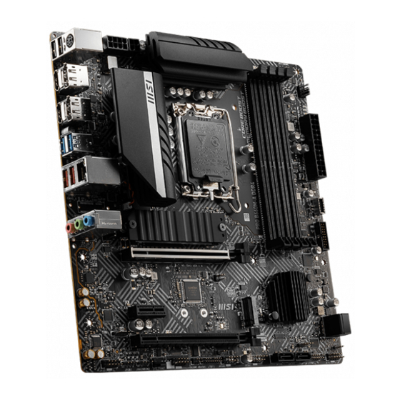
Page 11: Overview Of Components
JFP1 JRAINBOW1 JTPM1 SATA7 SATA8 CPU_FAN1 JUSB1 DIMMB2 DIMMB1 DIMMA2 JUSB2 DIMMA1 JTBT1 JDASH1 Processor JCOM1 Socket CPU_PWR2 SYS_FAN2 JRAINBOW2 CPU_PWR1 JRGB1 JAUD1... -
Page 12: Cpu Socket
Always unplug the power cord from the power outlet before installing or removing the CPU. ∙ Please retain the CPU protective cap after installing the processor. MSI will deal with Return Merchandise Authorization (RMA) requests if only the motherboard comes with the protective cap on the CPU socket. -
Page 13: Dimm Slots
It is recommended to use a more efficient memory cooling system for full DIMMs installation or overclocking. ∙ The stability and compatibility of installed memory module depend on installed CPU and devices when overclocking. ∙ Please refer to www.msi.com for more information on compatible memory. -
Page 14: Pci_E1~3: Pcie Expansion Slots
⚠ Important ∙ If you install a large and heavy graphics card, you need to use a tool such as MSI Graphics Card Bolster to support its weight to prevent deformation of the slot. ∙ For a single PCIe x16 expansion card installation with optimum performance, using the PCI_E1 slot is recommended. -
Page 15: M2_1~2: M.2 Slots (Key M)
M2_1~2: M.2 Slots (Key M) Please install the M.2 solid-state drive (SSD) into the M.2 slot as shown below. Installing M.2 module For M2_1 slot 1. Loosen the screws of M.2 SHIELD FROZR heatsink. 2. Remove the M.2 SHIELD FROZR and remove the protective films from the thermal pads. - Page 16 6. Put the M.2 SHIELD FROZR heatsink back in place and secure it. For M2_2 slot 1. Secure the supplied M.2 standoff according to your M.2 SSD length if need. 2. Insert your M.2 SSD into the M.2 slot at a 30-degree angle. 3.
-
Page 17: Sata5~8: Sata 6Gb/S Connectors
SATA5~8: SATA 6Gb/s Connectors These connectors are SATA 6Gb/s interface ports. Each connector can connect to one SATA device. SATA8 SATA6 SATA7 SATA5 ⚠ Important ∙ Please do not fold the SATA cable at a 90-degree angle. Data loss may result during transmission otherwise. -
Page 18: Cpu_Pwr1~2, Atx_Pwr1: Power Connectors
CPU_PWR1~2, ATX_PWR1: Power Connectors These connectors allow you to connect an ATX power supply. CPU_PWR1 Signal Name Signal Name Ground Ground Ground Ground CPU_PWR1 +12V +12V +12V +12V CPU_PWR2 Signal Name Signal Name Ground Ground CPU_PWR2 +12V +12V ATX_PWR1 Signal Name Signal Name +3.3V +3.3V... -
Page 19: Cpu_Fan1, Pump_Fan1, Sys_Fan1~2: Fan Connectors
CPU_FAN1, PUMP_FAN1, SYS_FAN1~2: Fan Connectors Fan connectors can be classified as PWM (Pulse Width Modulation) Mode or DC Mode. PWM Mode fan connectors provide constant 12V output and adjust fan speed with speed control signal. DC Mode fan connectors control fan speed by changing voltage. PWM Mode pin definition Signal Name Signal Name... -
Page 20: Jci1: Chassis Intrusion Connector
JCI1: Chassis Intrusion Connector This connector allows you to connect the chassis intrusion switch cable. Normal Trigger the chassis (default) intrusion event Using chassis intrusion detector 1. Connect the JCI1 connector to the chassis intrusion switch/ sensor on the chassis. 2. -
Page 21: Jusb4: Usb 3.2 Gen 1 5Gbps Type-C Connector
JUSB4: USB 3.2 Gen 1 5Gbps Type-C Connector This connector allows you to connect USB 3.2 Gen 1 5Gbps Type-C connector on the front panel. The connectors possess a foolproof design. When you connect the cable, be sure to connect it with the corresponding orientation. USB Type-C Cable JUSB4 USB Type-C port on... -
Page 22: Jusb1~2: Usb 2.0 Connectors
∙ In order to recharge your iPad, iPhone and iPod through USB ports, please install MSI Center utility. JTPM1: TPM Module Connector This connector is for TPM (Trusted Platform Module). Please refer to the TPM security platform manual for more details and usages. -
Page 23: Jtbt1: Thunderbolt Add-On Card Connector
JTBT1: Thunderbolt Add-on Card Connector This connector allows you to connect the add-on Thunderbolt I/O card. Signal Name Signal Name TBT_Force_PWR TBT_S0IX_Entry_REQ TBT_CIO_Plug_Event# TBT_S0IX_Entry_ACK SLP_S3#_TBT TBT_PSON_Override_N SLP_S5#_TBT Net Name Ground SMBCLK_VSB DG_PEWake SMBDATA_VSB TBT_RTD3_PWR_EN Ground TBT_Card_DET_R# PD_IRQ# JCOM1: Serial Port Connector This connector allows you to connect the optional serial port with bracket. -
Page 24: Jrgb1: Rgb Led Connector
Always turn off the power supply and unplug the power cord from the power outlet before installing or removing the RGB LED strip. ∙ Please use MSI’s software to control the extended LED strip. JRAINBOW1~2: Addressable RGB LED connectors The JRAINBOW connectors allow you to connect the WS2812B Individually Addressable RGB LED strips 5V. -
Page 25: Installing Os, Drivers & Msi Center
MSI Center is an application that helps you easily optimize game settings and smoothly use content creation softwares. It also allows you to control and synchronize LED light effects on PCs and other MSI products. With MSI Center, you can customize ideal modes, monitor system performance, and adjust fan speed. -
Page 26: Uefi Bios
UEFI has many new functions and advantages that traditional BIOS cannot achieve, and it will completely replace BIOS in the future. The MSI UEFI BIOS uses UEFI as the default boot mode to take full advantage of the new chipset’s ⚠... -
Page 27: Bios Setup
* When you press F10, a confirmation window appears and it provides the modification information. Select between Yes or No to confirm your choice. BIOS User Guide If you’d like to know more instructions on setting up the BIOS, please refer to http:// download.msi.com/manual/mb/Intel600BIOS.pdf ⚠ or scan the QR code to access. Important... -
Page 28: Resetting Bios
Updating BIOS Updating BIOS with M-FLASH Before updating: Please download the latest BIOS file that matches your motherboard model from MSI website. And then save the BIOS file into the USB flash drive. Updating BIOS: 1. Insert the USB flash drive that contains the update file into the USB port. - Page 29 ∙ Please close all other application software before updating the BIOS. To update BIOS: 1. Install and launch MSI Center and go to Support page. 2. Select Live Update and click on Advance button. 3. Select the BIOS file and click on Install button.
Need help?
Do you have a question about the PRO B660M-A WIFI DDR4 and is the answer not in the manual?
Questions and answers
3 ram sticks, 2x16gb 1x32gb which slots to get xmp to work?
To enable XMP with 2x16GB and 1x32GB RAM sticks on the MSI PRO B660M-A WIFI DDR4 motherboard, install the memory sticks in the DDR4 slots according to the following:
1. Place the 16GB sticks in slots that enable dual-channel mode (usually slots A2 and B2).
2. Place the 32GB stick in one of the remaining slots (A1 or B1).
Note: For best XMP support and stability, use matching memory modules. Mixing different capacities may limit XMP performance or cause instability.
This answer is automatically generated