Table of Contents
Advertisement
Quick Links
LA-5300 Broadcast Audio
Processor
LA-5300 Broadcast Audio Processor
Congratulations on your purchase of the Linear Acoustic LA-5300 Broadcast Audio Processor.
The LA-5300 provides everything broadcasters need to be ready for NEXTGEN TV/ATSC 3.0 audio in a
single, compact, integrated package, including:
Dolby® AC-4 encoding from PCM
Transcoding from Dolby Digital and Dolby Digital Plus to Dolby AC-4
Dolby AC-4 decoding for audience measurement watermarking and bitstream analysis and monitoring
Linear Acoustic UPMAX® ISC upmixing
Optional Verance and Nielsen watermarking
Loudness control via Dolby Real-Time Loudness Leveler (when encoding to Dolby AC-4)
Optionally, it also provides processing for a second legacy ATSC 1.0 program, including:
Dolby® Digital Plus (E-AC-3) and Dolby Digital (AC-3) encoding
Linear Acoustic UPMAX® ISC upmixing
Optional Verance and Nielsen watermarking
Loudness control via Linear Acoustic APTO® or Dolby Real-Time Loudness Leveler
Quick Start Guide
Hardware Overview
LA-5300 Front Panel
Advertisement
Table of Contents

Related Manuals for Telos Alliance LINEAR ACOUSTIC LA-5300


Summary of Contents for Telos Alliance LINEAR ACOUSTIC LA-5300
- Page 1 LA-5300 Broadcast Audio Processor LA-5300 Broadcast Audio Processor Congratulations on your purchase of the Linear Acoustic LA-5300 Broadcast Audio Processor. The LA-5300 provides everything broadcasters need to be ready for NEXTGEN TV/ATSC 3.0 audio in a single, compact, integrated package, including: Dolby®...
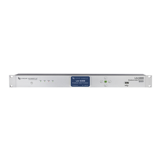
- Page 2 Figure 1 - Front panel The front panel of the LA-5300 includes the following: Reset button for restarting the unit from the front panel (1A) Four status LEDs indicating the status of each power supply (1B, 1C), the overall status of the unit (1D), and sync for the reference clock (1E) A color LCD display to show status and basic configuration parameters (1F) A five-button navigation cluster with Left, Right, Up, and Down arrows plus a green “OK”...
-
Page 3: Installation And Initial Setup
Two IEC power inlets for the redundant internal universal auto-ranging power supplies (2G) Note - Although the hardware is present for two independent SDI I/O paths, only the first SDI I/O is active at this time. The second path will be enabled in a future firmware update. Installation and Initial Setup Installation LA-5300 is a 1RU product intended to be permanently installed in a standard 19½”... - Page 4 Figure 3- Front panel home screen Setting IP Addresses LA-5300 ships with DHCP enabled and will automatically retrieve an IP address when connected to a network with a DHCP server. Important - The Control and AES67 Ethernet connections both require 1000BASE-T (Gigabit) switch ports in order to work properly.
- Page 5 Verify the information has been entered correctly and press the OK button to save the new values If you notice incorrect information and need to start over, use the Right button to highlight “Cancel” followed by the OK button Figure 4 - System information screen Figure 5 - IP configuration (control) screen If you are using AES67 I/O, pressing the Right button from the IP Configuration (Control) screen will bring you to the IP Configuration (AES67) screen.
- Page 6 1234 into the Password field (6B) then click the Log In button (6C). The ability to change the password will be included in an upcoming software update. Note - The Linear Acoustic LA-5300 is manufactured under license from Dolby Laboratories. Dolby, Dolby Audio, and the double-D symbol are trademarks of Dolby Laboratories.
-
Page 7: Front And Rear Panel Overview
Introduction The LA-5300 provides everything broadcasters need to be ready for NEXTGEN TV/ATSC 3.0 audio in a single, compact, integrated package, including: Dolby® AC-4 encoding from PCM Transcoding from Dolby Digital and Dolby Digital Plus to Dolby AC-4 Dolby AC-4 decoding for audience measurement watermarking and bitstream analysis and monitoring Linear Acoustic UPMAX®... - Page 8 Figure 1 - Front panel The front panel of the LA-5300 includes the following: Reset button for restarting the unit from the front panel (1A) Four status LEDs indicating the status of each power supply (1B, 1C), the overall status of the unit (1D), and sync for the reference clock (1E) A color LCD display to show status and basic configuration parameters (1F) A five-button navigation cluster with Left, Right, Up, and Down arrows plus a green “OK”...
- Page 9 Installation and Initial Setup Installation The LA-5300 is a 1RU product intended to be permanently installed in a standard 19½” equipment rack and secured with four standard rack screws. LA-5300 is fan cooled with air intakes and exhausts located on the side of the unit just behind the front panel, but whenever possible it is recommended to leave 1RU of empty space above and below the unit.
- Page 10 Figure 1- Front panel home screen Setting IP Addresses LA-5300 ships with DHCP enabled and will automatically retrieve an IP address when connected to a network with a DHCP server. Important - The Control and AES67 Ethernet connections both require 1000BASE-T (Gigabit) switch ports in order to work properly.
-
Page 11: Locate Mode
Figure 2 - System information screen Figure 3 - IP configuration (control) screen If you are using AES67 I/O, pressing the Right button from the IP Configuration (Control) screen will bring you to the IP Configuration (AES67) screen. The steps for configuring this port are identical to those above for the Control port. -
Page 12: Factory Reset
When you enable the “Locate Mode” from the remote user interface, the unit’s front panel display will repeatedly change color until Locate Mode has been cleared by pressing any key on the front panel or by clicking again on the “Locate Mode” button on the remote user interface. Enabling Locate Mode affects only the unit’s display and has no effect on the audio. - Page 13 same network and subnet as the LA-5300. Note - This section is primarily an overview of the user interface to provide an explanation of the various menus and screens. It is not intended to provide step-by-step instructions for setting up or operating the LA-5300.
- Page 14 Figure 1 - Home screen before logging in Additional menus become visible once you are logged in. These include the encoding, upmixing, watermarking, and monitor controls for the Program 1 (Dolby AC-4) encoder (2A), the same controls for the Program 2 (Dolby Digital Plus) encoder (2B), the I/O menus (2C) which include clock, GPI/O, and delay controls, detailed system-wide information and configuration settings (2D) which includes the IP configuration menu, and the Log Out button (2E).
- Page 15 in the Preset menu (3C) for easy recall. Note that there are no factory presets, and so the menu field will appear blank until a user preset is created and saved. Clicking on the Preset management icon (3E) reveals a dropdown menu with the following options: Save: Saves the current Program 1 settings to the selected preset, immediately over-writing the previous settings associated with the preset;...
- Page 16 Input and Output Routing Connect your SDI, AES-3, and/or AES67 sources to the rear panel of the LA-5300 as required for your installation. The LA-5300 can access any of the eight audio pairs carried in the incoming HD- or SD-SDI streams applied to SDI Input 1.
- Page 17 Figure 2 - Signal routing menu Creating an Input Group Click on your first audio input source (3A) to highlight it, then right-click and select “Create Input Group.” You may enter a custom name for this source in the Label field (3C) and customize the color (3B) of the graphical routing lines.
- Page 18 Figure 3- Creating an input group Routing Audio to the Program Input After saving the input group, it is necessary to first set the priority of the input source by dragging the input audio lines (4A) and then clicking when the desired priority level (4B) is highlighted. The LA-5300 will look for audio first on inputs connected to Priority 1.
- Page 19 Figure 5 - Selecting the input signal type To edit or delete a group, highlight then right-click the colored Edit rectangle (6A). Figure 6 - Editing or deleting an input group Creating an Output Group The steps for creating an output group are identical to creating an input group, but with the Outputs menu. Routing Audio to the Program Output Once the first output group has been created and saved, drag the output audio lines from the group to the desired program output, then click to save.
-
Page 20: Sample Rate Converters
Figure 7 - Delays menu Sample Rate Converters Sample rate converters (SRCs) are provided on each SDI input pair, each SDI output pair of the first SDI output, and each AES-3 input pair. The AES-3 output is always synced to the active reference clock. There are no SRCs in the AES67 path. -
Page 21: Clock Reference
Figure 8 - Sample rate converters Clock Reference Because the LA-5300 offers very flexible signal routing and supports multiple input and output formats, having a firm grasp of the clock sync (reference) requirements is critical. Clock Reference Requirements Reference clock source options include: Internal 48kHz SDI Input AES-3 Input... - Page 22 Figure 9 - Clock reference GPI/O LA-5300 offers five GPI and five GPO functions through its rear panel DB-15 connector, activated by a momentary contact closure. GPI/O Pinout Function Function Pin 1 +5VDC Pin 9 +5VDC Pin 2 GPI 1 Pin 10 GPO 1 Pin 3...
- Page 23 Figure 10 - GPI/O pinout GPI/O Functions GPI functions (11A) include: None Reboot/Reset Unit Hardware (Relay) Bypass Processing/Encoding Preset I/O Preset Show Preset (Processing/Encoding + I/O presets) GPO functions (11D) include: None GPI Passthrough Power Supply 1 up Power Supply 2 up Power Supply 1 down Power Supply 2 down Unit resetting...
-
Page 24: System Menu Overview
Unit above temperature Unit bypass (relay bypass) active Change in reference Primary reference clock is lost Secondary reference is lost Primary reference clock is active Secondary reference is active Internal reference is active Figure 11 - GPI/O menu The State Indicator (11B) for each function will light for the duration of the closure on GPIs. For GPOs, it will light for the duration of the active event. - Page 25 System Screen The main system screen contains a wealth of technical status information about the device hardware and software (1A). Some of it relates to the overall health of the unit (such as Power Supply status and unit uptime) but most information will only be required during the course of troubleshooting an issue with our support team or performing software updates.
- Page 26 Figure 1 - System screen IP Configuration Clicking on the IP Menu (2A) reveals the controls for DHCP settings plus fields for entering static IP addresses, subnets, and gateways for both the Control and AES67 Ethernet ports as well as network activity and status.
- Page 27 Figure 2 - IP configuration menu By default, LA-5300 is set up with DHCP enabled and will automatically receive an IP address when its Control Ethernet port is connected to a network with a DHCP server. To use a fixed IP address, click the Edit button (2D) for the appropriate port which unlocks the settings. (Please note the Edit button of the AES67 port is used for illustration in Figure 2 and is replaced by the Cancel and Apply buttons once you click on it).
- Page 28 Basic Dolby AC-4 Encoder Menu Basic parameters include Channel Mode (1A), Frame Rate (1B), Bit Rate (1C), audio Type (1G), Loudness Regulation (1F), Language (1E), and Dialogue Normalization (1D). Figure 1 - Basic Dolby AC-4 encoder menu Channel Mode The Channel Mode control (1A) sets the configuration of the audio output channels embedded in the AC-4 bitstream.
- Page 29 introducing A/V sync errors during source switching, much like Dolby E or ED2. The frame rate control (1B) should be set to match the video frame rate in your particular workflow. Select “Native” when there is no video reference available Bit Rate The Dolby AC-4 codec provides increased efficiency compared with Dolby AC-3 (Dolby Digital) to allow for the delivery of Dolby Atmos and multi-language content.
- Page 30 dialogue; it specifies a deviation of +/- 0.5LU and a peak level below -1dBTP ATSC A/85: Used in the United States and serving as the foundation and reference for the CALM Act; whenever possible, the anchor element of the audio (typically dialogue) should be measured and normalized to a target of -24dB LKFS, +/- 2dB which is accomplished here by enabling the dialogue intelligence feature ARIB TR-B32: The Japanese broadcast standard that uses a relative gate (per ITU BS 1770-2, like...
- Page 31 Lo/Ro: The Center and surround channel content is redirected to the Left and Right channels for playback in a system with only two speakers PL: This is a Dolby Surround-compatible matrix-encoded downmix that contains content from all channels and downmixes them to the Left and Right channels; this downmix is intended to be decoded by a Dolby Surround Pro Logic decoder which can extract the matrix-encoded content from the Left and Right channels to produce a four- or five-channel output with mono surround channels PLII: This is a Lt/Rt downmix that retains the stereo surround information from the original program;...
- Page 32 Figure 2 - Top portion of Dolby AC-4 encoder menu Preprocessing Mode Setting the Preprocessing Mode control (3A) to “Auto” grays out the associated controls in the “Previous Parameters” (3B) section and uses upstream metadata to determine individual control settings. Placing it in “Manual”...
- Page 33 “Not Applied” indicates surround attenuation has not been applied upstream and will be added by the encoder. “Unknown” should be selected in situations where it is not known whether or not surround attenuation has been applied. Previous Mix Type (2 channel) If the downmix type is known and present in the incoming metadata stream, set this control to “Auto”...
- Page 34 can be manually set. Lower settings provide more gentle level control and are best suited for content that has already been processed for compliance either in the file domain or by a real-time processor upstream. Higher settings gradually increase the amount of processing and are more suitable when program content levels vary.
-
Page 35: Confidence Monitoring
Confidence Monitoring The LA-5300 includes a Dolby AC-4 decoder for confidence monitoring. Monitor audio is routed to the channels immediately following those used for the bitstream output. For example, if the AC-4 bitstream occupies output channels 1 and 2 and the confidence decoder’s channel mode is 5.1, the monitor audio would be present on output channels 3 through 8. - Page 36 Figure 4 - Monitor menu for AC-4 decoder Basic Dolby Digital Plus Encoder Menu Clicking on the Dolby Digital Plus Encoder dropdown menu from the Program 2 screen reveals the basic encoder controls. There is a separate dropdown menu for advanced controls. Basic parameters include Encoder Mode (5A), Channel Mode (5B), Bit Rate (5D), Loudness Method (5E), and Dialogue Normalization (5C).
- Page 37 Figure 5 - Basic Dolby Digital Plus encoder menu Encode Mode Use the Encode Mode control (5A) to choose between Dolby Digital Plus (E-AC-3) or Dolby Digital (AC-3). For ATSC 1.0 applications, Dolby Digital is the proper choice. Channel Mode The Channel Mode control (5B) determines the channel output mode of the encoder, either 2.0 (L,R) for 2- channel content, or 5.1 (L,R,C,LFE,Ls,Rs) for 5.1-channel content.
- Page 38 Dialogue Normalization The Dialogue Normalization control (5C) sets the dialnorm metadata value in the Dolby AC-3 or E-AC-3 bitstream, which is the same as the desired output loudness target level. For ATSC A/85, this is normally set to -24dB. Advanced Dolby Digital Plus Encoder Menu The advanced parameters menu contains controls that determine whether certain settings and metadata values are set automatically or manually, and, if set manually, the values of individual settings.
- Page 39 Music Light: Provides a 12dB null band around the loudness target and uses lower ratios to preserve the dynamics of genres such as classical and jazz Speech: Provides a 5dB null band but higher ratios to more effectively deal with the varying levels and high peaks typically found in speech Downmix Gain Controls The Downmix Gain controls (6D) can be individually set for the Lo/Ro Surround, Lo/Ro Center, Lt/Rt...
- Page 40 Figure 6 - Advanced Dolby Digital Plus encoder menu UPMAX® Upmixing The LA-5300 uses the same new upmixing algorithm found in the Linear Acoustic UPMAX® ISC. If the channel count and format of the incoming content matches the desired output format, the LA-5300 will pass it through as-is.
- Page 41 Figure 1 - Basic UPMAX control grouping Preset and Format Controls UPMAX processing is largely based on presets. Several factory presets are included which can be used as- is or serve as starting points for a custom user preset. Preset Menu Use the Preset dropdown menu (2C) to choose a preset.
- Page 42 Output Format Menu The Output Format menu (2A) determines the output channel configuration. Output options include: 5.1: Provides a constant 5.1-channel output from Stereo, Stereo + Dialog, and 5.1-channel input sources 5.1 Legacy: Like the standard 5.1 output, it provides a constant 5.1-channel output from Stereo, Stereo + Dialog, and 5.1-channel input sources but with upmixing that is sonically closer to the previous UPMAX algorithm used in the Linear Acoustic UPMAX v4 upmixer and the algorithm employed in the various Linear Acoustic AERO®-series processors...
- Page 43 Figure 2 - UPMAX preset and format controls LFE Channel Controls The LFE Channel controls are used to tune the crossover frequencies, gain, and signal routing of the low frequency effects audio. LFE Crossover The LFE Crossover control (3B) defines the crossover frequency at which to extract the low frequency signal routed to the LFE Channel and is typically set between 60 and 100Hz.
- Page 44 Figure 3 - UPMAX LFE Channel controls Center Width Controls These controls define the routing of the LF and HF bands across the Left, Center and Right Channels. Used in combination with the Mid-Bass Crossover frequency control, the provide the ability to craft the image of the Front Channels in a way that maintains a direct sonic-visual association of dialog while providing a...
- Page 45 pleasant and wide image of the phase-correlated elements. Though values are expressed in a decimal format, they easily correlate to a percentage value (0.00 = 0%, 0.05 = 50%, 1.00 = 100%, etc.). The LF Center Width control (4B) determines the amount of LF audio routed to the Center versus the Left and Right Channels.
- Page 46 Figure 4 - UPMAX Center Width controls Auto-Detect Controls When the Input Format is set to Auto-Detect, the LA-5300 continuously monitors the input signal to determine its format and will automatically switch to Stereo, Stereo + Dialog, or 5.1-channel processing modes.
- Page 47 Figure 5 - UPMAX Auto-Detect controls Advanced UPMAX Menu The Advanced parameters are included for audio experts who wish to dig deep and tweak settings for very specific applications or demanding tastes. They are not required for most users and are accordingly not displayed by default.
- Page 48 In order for a stereo downmix to render at the same level as the original stereo source that was upmixed, the gain applied to the rear channels must be the inverse of the Dolby Rear Channel Downmix Level. Put another way, if you want a 3dB boost in the rear channels, the Rear Channel Downmix Level control (6F) should be set to -3.
- Page 49 Figure 6 - UPMAX Advanced menu controls Nielsen® and Verance® Watermark Encoding The LA-5300 includes optional support for audience measurement watermarking from both Nielsen and Verance. In both applications, proprietary and customer-specific information is required and is provided by the vendor. Nielsen Watermark Encoding Set the Nielsen Watermark Enable control (1B) to “On”...
- Page 50 generated. Please check with Nielsen to determine the correct process for your station. Supported processes include N2, N6, N2+N6, CBET, CBET+N6, and CBET+N2+N6. Use the SDI, Check Digit, CSID, and CBET Check Digit fields (1C) to enter the proper codes as provided by Nielsen for your individual station.
- Page 51 Set the Verance Watermark Enable control (2B) to “On” to enable the encoder. Check the Status window (2C) to verify that the encoder is running. The Calibrate control (2A) is used in conjunction with a special audio test file to measure delay when the Verance watermark is inserted.
- Page 52 APTO® Processing LA-5300 units equipped with the Dolby Digital Plus Encoder for a second program source offer a choice of loudness control options including Dolby’s own Real Time Loudness Leveler (RTLL) and Linear Acoustic® APTO processing. There are no dedicated controls when using the RTLL option, but APTO is a bit more complex and requires some additional explanation.
- Page 53 The Adaptation control (1B) determines how much processing is applied to the incoming signal in the Dynamic Range processing stage, and, in combination with various individual controls, determines dynamic range of the output audio The ideal amount of Adaptation depends upon both the source content and on the destination platform. Content that has been pre-analyzed for loudness, scaled, and normalized in the file domain will require less realtime processing than, say, live sports, which can have rather unpredictable audio levels.
- Page 54 Adaptive Input Detection is especially useful when source audio levels are unknown or are likely to vary widely as it allows the Dynamic Range processing stage to respond more predictively the actual incoming content. If the incoming content has already been analyzed and loudness-corrected in the file domain, less overall processing is required and a more natural-sounding output can be achieved by setting the Average Input Level to the same value as the target level used during file-based correction and reducing the value of the Adaptive Input Percentage control (also found in the Advanced menu) or disabling Adaptive Input...
- Page 55 Figure 1 - Basic APTO controls Advanced APTO Controls As we’ve mentioned before, most users and applications will be well served by simply selecting the appropriate factory profile according either to compliance regulations. At most, some adjustments to the Basic controls may be necessary. Unless there are extenuating circumstances or the need to solve a particular problem with highly difficult programming, adjusting the Advanced parameters described below is rarely necessary.
- Page 56 many seconds of continuous speech are required for the measurements to be considered reliable and valid, and after which the Compliance processing stage adaptively switches to dialog normalization mode A minimum of 5 seconds is recommended. Shorter values may incorrectly factor in non-dialog material, and significantly longer values may cause unnecessary delays in engaging dialog normalization processing, especially in content with shorter segments of continuous dialog.
- Page 57 The primary goal of APTO processing is to deliver a consistent average output level as set by the Target Level control. This does not mean, however, that the actual output audio level must never deviate from this value. In fact, a certain amount of dynamic range helps preserve the artistic integrity of the original programming and makes for a more engaging audio experience for the viewer.
- Page 58 The Average Maximum Attenuation control (2J) sets the maximum amount of negative gain (gain reduction) applied in the Compliance processing stage in order to reach the Target level. Larger values will allow loud program segments to be reduced by a greater amount. However, setting this control too high –...
-
Page 59: Specifications
In these cases where the average input level is not easy to predict, it is best to enter a value that matches the output target loudness value, enable Adaptive Input Detection, and take advantage of APTO’s intelligent dynamics processing. Figure 2 - Advanced APTO controls Specifications Processing Loudness Control... - Page 60 Acoustic APTO™ Upmixing Linear Acoustic UPMAX® ISC upmixing Decoding Decodes Dolby Digital (AC-3), Dolby Digital Plus (E-AC-3), and Dolby AC-4 at the input for watermarking, bitstream analysis, and monitoring Supports Dolby AC-4 pass-through Transcoding Transcodes Dolby Digital and Dolby Digital Plus to Dolby AC-4 Encoding Encodes to Dolby AC-4 with Dolby Real Time Loudness Leveler (RTLL) Optional encoding of second program to Dolby Digital Plus (E-AC-3) or Dolby Digital (AC-3) with Dolby...
- Page 61 SDI input to SDI output with SRCs disabled: 33.5ms SDI input to SDI output with SRCs enabled: 36.5ms AES67 input to AES67 output: 107ms (measurement made using Telos Alliance SDI xNode which has a latency value of 80ms) Latency is subject to change depending upon software version...
-
Page 62: Front Panel Controls And Indicators
Parallel GPI/O Control Port 15-pin female D connector, 0-5V TTL levels; 5 inputs, 5 outputs Front Panel Controls and Indicators 5-key navigation cluster; graphical color LCD display; LED status indicators for each power supply, status, and reference Power Dual internal redundant auto-ranging power supplies, each rated at 100-264VAC, 50/60Hz, 100 Watts maximum Dimensions and Weight 19”W x 9”D x 1.75”... -
Page 63: Warranty
Decisions 2005/618/EC, 2005/717/EC, 2005/747/EC (RoHS directive), and WEEE Licensing The Linear Acoustic LA-5300 is manufactured under license from Dolby Laboratories; Dolby, Dolby Audio, and the double-D symbol are trademarks of Dolby Laboratories. The NEXTGEN TV logo is an unregistered trademark of the Consumer Technology Association and is...
Need help?
Do you have a question about the LINEAR ACOUSTIC LA-5300 and is the answer not in the manual?
Questions and answers