Table of Contents
Advertisement
Advertisement
Table of Contents

Related Manuals for MSI K8NGM-V


Summary of Contents for MSI K8NGM-V
- Page 1 K8NGM2 Series MS-7207 (v2.X) Micro-ATX Mainboard G52-M7207X5...
- Page 2 FCC-B Radio Frequency Interference Statement This equipment has been tested and found to comply with the limits for a class B digital device, pursuant to part 15 of the FCC rules. These limits are designed to provide reasonable protection against harmful interference in a residential installation. This equipment generates, uses and can radiate radio frequency energy and, if not installed and used in accordance with the instruction manual, may cause harmful interference to radio communications.
-
Page 3: Copyright Notice
This device complies with Part 15 of the FCC Rules. Operation is subject to the following two conditions: (1) this device may not cause harmful interference, and (2) this device must accept any interference received, including interference that may cause undesired operation Copyright Notice T he material in this document is the intellec tual property of M ICRO-STAR INTERNATIONAL. -
Page 4: Technical Support
Alternatively, please try the following help resources for further guidance. † Visit the MSI homepage & FAQ site for technical guide, BIOS updates, driver updates, and other information: http://www.msi.com.tw & http://www.msi. -
Page 5: Weee Statement
WEEE Statement... -
Page 8: Table Of Contents
CONTENTS FCC-B Radio Frequency Interference Statement ............ii Copyright Notice ......................iii Technical Support ......................iv Safety Instructions ......................iv WEEE Statement ......................v Chapter 1. Getting Started ..................1-1 Mainboard Specifications ................... 1-2 Mainboard Layout ....................1-5 Packing Checklist ....................1-6 Chapter 2. - Page 9 Chassis Intrusion Switch Connector: JCI1 ..........2-18 SPDIF-Out/ SPDIF-In Connector: JSPDO1/JSPDI1 (SPDIF-In is optional) 2-19 Audio-out Connector: J1 ................2-19 Serial Port Header: JCOM1 (Optional) ............. 2-20 IEEE 1394 Connectors: J1394_1 (Optional) ..........2-20 Front Panel Connector: JFP1/JFP2 ............2-21 IrDA Infrared Module Header: JIR1............2-21 TV-Out Connector: JTV1 (For GeForce 6150 Only, Optional) ....
- Page 10 Access Point Mode ..................4-7 WLAN Card Mode ..................4-8 Live Update ......................4-9 MEGA STICK ....................... 4-10 Basic Function ................... 4-10 Non-Unicode programs supported ............4-12 PC Alert ....................... 4-14 Power on Agent ....................4-15 Power Off / Restart ................... 4-16 Start W ith ....................
- Page 11 Mixer ......................A-8 AudioIO ....................... A-12 S/PDIF ......................A-15 Microphone ....................A-17 3D Audio Demo ................... A-18 Information ....................A-19 Using 2-, 4-, 6- & 8- Channel Audio Function ..........A-20 Appendix B: Using the TV-Out Function (HDTV-Out Integrated) ....B-1 Installing the TV-Out Bracket ................
-
Page 12: Chapter 1. Getting Started
Getting Started Ch ap ter 1 . Get ti ng Started Getting Started Thank you for choosing the K8NGM2 Series (MS-7207 v2.X) Micro ATX mainboard. The K8NGM2 Series mainboards are based on ® ® nVidia GeForce 6150/6100 & nVidia nForce 430/410 chipsets ®... -
Page 13: Mainboard Specifications
MS-7207 M-ATX Mainboard Mainboard Specifications † Supports 64-bit AMD ® K8 Athlon64/ Athlon64FX processor (Socket 939). † Supports 4800+ and higher CPU. (For the latest information about CPU, please visit http://www.msi.com.tw/pro- gram/products/mainboard/mbd/pro_mbd_cpu_support.php) Chipset † nVidia ® GeForce 6150/6100 Chipset (Optional) - HyperTransport connection to AMD K8 Athlon64 processor. - Page 14 Getting Started MSI Reminds You... 1. Please note that users cannot install OS, either WinME or Win98, in their SATA hard drives. Under these two OSs, SATA can only be used as an ordinary storage device. 2. To create a bootable RAID volume for a Windows 2000 environment, Microsoft’s Windows 2000 Service Pack 4 (SP4) is required.
- Page 15 The 1394 GUID address is burnt in the BIOS core. If the 1394 GUID address is lost due to an unpredictable event, such as replac- ing a new BIOS chip, users can use the utility from MSI’s website by entering the 1394 GUID address to recover its original one.
-
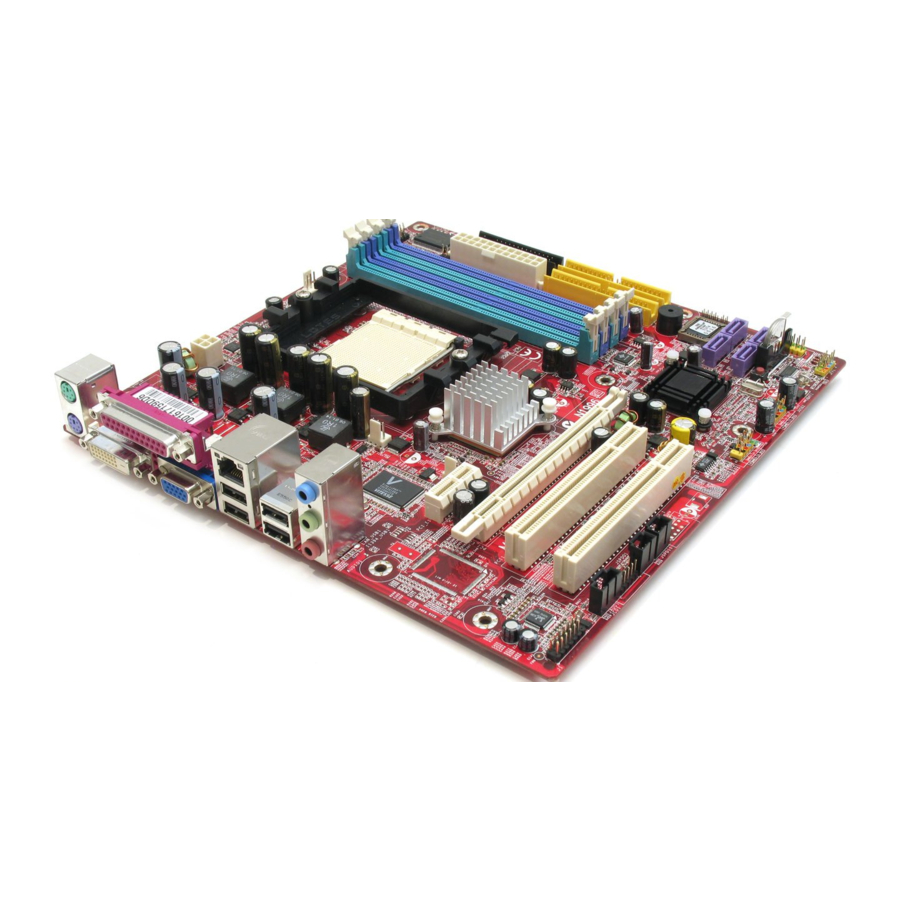
Page 16: Mainboard Layout
Getting Started Mainboard Layout K8NGM2 Series (MS-7207 v2.X) M-ATX Mainboard... -
Page 17: Packing Checklist
MS-7207 M-ATX Mainboard Packing Checklist MSI Driver/Utility CD SATA Cable (Optional) MSI motherboard Standard Cable for Standard Cable for Power Cable (Optional) Floppy Disk IDE Devices 1394 Bracket (Optional) USB Bracket (Optional) Back IO Shield Audio-out Bracket TV-out Bracket User’s Guide... -
Page 18: Chapter 2. Hardware Setup
Hardware Setup Chapter 2. Hardware Setup Hardware Setup This chapter tells you how to install the CPU, memory modules, and expansion cards, as well as how to setup the jumpers on the mainboard. Also, it provides the instructions on connecting the pe- ripheral devices, such as the mouse, keyboard, etc. -
Page 19: Quick Components Guide
MS-7207 M-ATX Mainboard Quick Components Guide JTV1, p.2-22 JPW1, p.2-9 CPUFAN1, p.2-15 DDR DIMMs, p.2-7 JCOM1, p.2-20 CPU, p.2-3 Back Panel I/O, p.2-10 JCI1, p.2-18 FDD1, p.2-15 ATX1, p.2-9 SYSFAN1, p.2-15 N B F A N 1 , p.2-15 IDE1/2, p.2-16 PCI Express Slots, p.2-25 SATA1~4,... -
Page 20: Central Processing Unit: Cpu
If you do not have the heat sink and cooling fan, contact your dealer to purchase and install them before turning on the computer. For the latest information about CPU, please visit http://www.msi.com.tw/pro- gram/products/mainboard/mbd/pro_mbd_cpu_support.php. MSI Reminds You... -
Page 21: Cpu Installation Procedures For Socket 939
MS-7207 M-ATX Mainboard CPU Installation Procedures for Socket 939 1. Please turn off the power and unplug the power cord before Open Lever installing the CPU. Sliding 90 degree Plate 2. Pull the lever s ideways away from the socket. Make sure to raise the lever up to a 90-de- gree angle. -
Page 22: Installing Amd Athlon64 Cpu Cooler Set
MSI Reminds You... Mainboard photos shown in this section are for demonstration of the cooler installation for Socket 939 CPUs only. The appearance of your mainboard may vary depending on the model you purchase. - Page 23 Safety Hook Fixed Lever Fixed Bolt MSI Reminds You... While disconnecting the Safety Hook from the fixed bolt, it is necessary to keep an eye on your fingers, because once the Safety Hook is discon- nected from the fixed bolt, the fixed lever will spring back instantly.
-
Page 24: Memory
128MB~1GB 128MB~1GB 128MB~1GB Dual Channel MSI Reminds You... - In dual-channel mode, make sure that you install memory modules of the same type and density on DDR DIMMs. - To enable successful system boot-up, always insert the memory modules into the DIMM1 slots first. -
Page 25: Installing Ddr Modules
MS-7207 M-ATX Mainboard Installing DDR Modules The DDR DIMM has only one notch on the center of module. The module will only fit in the right orientation. Insert the DIMM memory module vertically into the DIMM slot. Then push it in until the golden finger on the memory module is deeply inserted in the socket. -
Page 26: Power Supply
Pin Definition JPW1 SIGNAL MSI Reminds You... 1. These two connectors connect to the ATX power supply and have to work together to ensure stable operation of the mainboard. 2. Power supply of 350 watts (and above) is highly recommended for system stability. -
Page 27: Back Panel
MS-7207 M-ATX Mainboard Back Panel 1394 Port L-In Parallel (Optional) M ou se L-Out DVI Port VGA Port Keyboard (for GeForce 6150) Ports Ports (optional) Mouse/Keyboard Connector ® The mainboard provides a standard PS/2 mouse/keyboard mini DIN connector ® ® for attaching a PS/2 mouse/keyboard. -
Page 28: Digital Panel Connector (For Geforce 6150 Only)(Optional)
T.M.D.S. Clock Shield T.M.D.S. Data1/3 Shield T.M.D.S. Clock+ T.M.D.S. Clock- MSI Reminds You... Please note that the DVI connector doesn’t support to connect the D- Sub to DVI converter. USB Connectors The mainboard provides an OHCI (Open Host Controller Interface) Universal Serial Bus root for attaching USB devices such as keyboard, mouse or other USB- compatible devices. -
Page 29: Lan (Rj-45) Jack:10/100 Lan (Rtl8201Cl) Or Giga-Bit Lan (Vsc8201Rx : Optional)
MS-7207 M-ATX Mainboard LAN (RJ-45) Jack:10/100 LAN (RTL8201CL) or Giga-bit LAN (VSC8201RX : optional) The mainboard provides 1 standard RJ-45 jack for connection to single Local Area Network (LAN). This LAN enables data to be transferred at 10/ 100Mbps or (1000Mbps for VSC8201RX only). -
Page 30: Audio Port Connectors & Audio Header (J1)
Center and Subwoofer Out Line Out Side Surround Out M IC MSI Reminds You... For the advanced functions of the audio codec, please refer to Appen- dix A: Introduction to Realtek ALC880 for details. IEEE 1394 Port (optional) There is one 1394 port on the back panel providing the connection for 1394 devices. -
Page 31: Parallel Port Connector: Lpt1
MS-7207 M-ATX Mainboard Parallel Port Connector: LPT1 The mainboard provides a 25-pin female centronic connector as LPT. A parallel port is a standard printer port that supports Enhanced Parallel Port (EPP) and Ex- tended Capabilities Parallel Port (ECP) mode. Pin Definition SIGNAL DESCRIPTION STROBE... -
Page 32: Connectors
CPU fan control. +1 2V SENSOR +1 2V +1 2V SENSOR SENSOR SYSFAN1 NBFAN1 CPUFAN1 MSI Reminds You... ® Please refer to the recommended CPU fans at AMD official website or consult the vendors for proper CPU cooling fan. 2-15... -
Page 33: Ata133 Hard Disk Connectors: Ide1 & Ide2
IDE2 (Secondary IDE Connector) IDE2 can also connect a Master and a Slave drive. MSI Reminds You... If you install two hard disks on cable, you must configure the second drive to Slave mode by setting its jumper. Refer to the hard disk docu- mentation supplied by hard disk vendors for jumper setting instructions. -
Page 34: Serial Ataii Connectors: Sata1~Sata4
Serial ATA cable Take out the dust cover and connect to the hard disk devices Connect to SATA1/2/3/4 MSI Reminds You... Please do not fold the Serial ATA cable into 90-degree angle. Otherwise, data loss may occur during transmission. 2-17... -
Page 35: Cd-In Connector: Jcd1
MS-7207 M-ATX Mainboard CD-In Connector: JCD1 This connector is provided for CD-ROM audio. JCD1 Front Panel Audio Connector: JAUD1 The JAUD1 front panel audio connector allows you to connect to the front ® panel audio and is compliant with Intel Front Panel I/O Connectivity Design Guide. -
Page 36: Spdif-Out/ Spdif-In Connector: Jspdo1/Jspdi1 (Spdif-In Is Optional)
Hardware Setup SPDIF-Out/ SPDIF-In Connector: JSPDO1/ JSPDI1 (SPDIF-In is optional) These connectors are used to connect SPDIF (Sony & Philips Digital Intercon- nect Format) interface for digital audio transmission. The JSPDO1 is for SPDIF-Out and the JSPDI1 is for SPDIF-In. SPDIF-Out SPDIF-In JSPDI1... -
Page 37: Serial Port Header: Jcom1 (Optional)
MS-7207 M-ATX Mainboard Serial Port Header: JCOM1 (Optional) The mainboard offers one 9-pin header as serial port. The port is a 16550A high speed communication port that sends/receives 16 bytes FIFOs. You can attach a serial mouse or other serial device directly to it. Pin Definition JCOM1 SIGNAL... -
Page 38: Front Panel Connector: Jfp1/Jfp2
Hardware Setup Front Panel Connector: JFP1/JFP2 The mainboard provides one front panel connector for electrical connection to ® the front panel switches and LEDs. The JFP1 is compliant with Intel Front Panel I/O Connectivity Design Guide. JFP1 Pin Definition SIGNAL DESCRIPTION Power Power... -
Page 39: Tv-Out Connector: Jtv1 (For Geforce 6150 Only, Optional)
TV-Out Connector TV-Out Connector (RCA Composite) (S-Video) MSI Reminds You... 1. Please note that the TV-Out bracket supports to connect one TV only. Meanwhile you can not connect two TVs to this bracket. Otherwise, the TVs will not be functional. -
Page 40: Front Usb Connectors: Jusb1/ Jusb2
JUSB1, JUSB2 USB4+ USB5+ (USB 2.0) Key (no pin) USBOC Connected to JUSB1 or JUSB2 (yellow connectors) USB 2.0 Bracket (Optional) MSI Reminds You... Note that the pins of VCC and GND must be connected correctly to avoid possible damage. 2-23... -
Page 41: Button
MS-7207 M-ATX Mainboard Button The motherboard provides the following button for you to set the computer’s function. This section will explain how to change your motherboard’s function through the usage of the button. Clear CMOS Button: SW1 There is a CMOS RAM on board that has a power supply from external battery to keep the system configuration data. -
Page 42: Slots
Hardware Setup Slots The motherboard provides one PCI Express x16 slot, one PCI Express x1 slot, and two 32-bit PCI bus slots. PCI Express Slots The PCI Express slot, as a high-bandwidth, low pin count, serial, interconnect technology. PCI Express architecture provides a high performance I/O infrastructure for Desktop Platforms with transfer rates starting at 2.5 Giga transfers per second over a PCI Express x1 lane for Gigabit Ethernet, TV Tuners, 1394 controllers, and general purpose I/O. -
Page 43: Chapter 3. Bios Setup
SETUP. ² You want to change the default settings for customized features. MSI Reminds You... 1. The items under each BIOS category described in this chapter are under continuous update for better system performance. Therefore, the description may be slightly different from the latest BIOS and should be held for reference only. -
Page 44: Entering Setup
MS-7207 M-ATX Mainboard Entering Setup Power on the computer and the system will start POST (Power On Self Test) process. W hen the message below appears on the screen, press <DEL> key to enter Setup. Press DEL to enter SET UP If the message disappears before you respond and you still wish to enter Setup, restart the system by turning it OFF and On or pressing the RESET button. -
Page 45: Getting Help
BIOS Setup Getting Help After entering the Setup menu, the first menu you will see is the Main Menu. M ain M enu The main menu lists the setup functions you can make changes to. You can use the control keys ( to select the item. -
Page 46: The Main Menu
MS-7207 M-ATX Mainboard The Main Menu ® Once you enter AMI BIOS CMOS Setup Utility, the Main Menu (Figure 1) will appear on the screen. The Main Menu allows you to select from twelve setup func- tions and two exit choices. Use arrow keys to select among the items and press <Enter>... - Page 47 BIOS Setup Cell_M enu This menu shows the frequency of CPU. Load Fail-Safe Defaults Use this menu to load the default values set by the BIOS vendor for stable system performance. Load Optimized Defaults Use this menu to load the default values set by the mainboard manufacturer specifi- cally for optimal performance of the mainboard.
-
Page 48: Standard Cmos Features
MS-7207 M-ATX Mainboard Standard CMOS Features The items in Standard CMOS Features Menu are divided into several categories. Each category includes no, one or more than one setup items. Use the arrow keys to highlight the item and then use the <PgUp> or <PgDn> keys to select the value you want in each item. - Page 49 BIOS Setup Dev ice This item shows the information about the specified item (Read-only). Type This item defines the HDD parameters. LBA/Large M ode This item allows you to enable or disable the LBA (Logical Block Address, logical block size in hard disk) mode. Setting options: [Auto], [Disabled]. Block Mode W hen the setting is Auto, it will read or write more sector at every circle to enhance the hard disk performance.
- Page 50 MS-7207 M-ATX Mainboard Hard Disk S.M.A.R.T. This allows you to activate the S.M.A.R.T. (Self-Monitoring Analysis & Reporting Technology) capability for the hard disks. S.M.A.R.T is a utility that monitors your disk status to predict hard disk failure. This gives you an opportunity to move data from a hard disk that is going to fail to a safe place before the hard disk becomes offline.
-
Page 51: Advanced Bios Features
BIOS Setup Advanced BIOS Features Quick Boot Select Enabled to reduce the amount of time required to run the power-on self-test (POST). A quick POST skips certain steps. We recommend that you normally disable quick POST. It is better to find a problem during POST than lose data during your work. Setting options: [Enabled], [Disabled]. - Page 52 MS-7207 M-ATX Mainboard IOAPIC Function This field is used to enable or disable the APIC (Advanced Programmable Interrupt Controller). Due to compliance with PC2001 design guide, the system is able to run in APIC mode. Enabling APIC mode will expand available IRQ resources for the system. Setting options: [Enabled], [Disabled].
-
Page 53: Advanced Chipset Features
BIOS Setup Advanced Chipset Features MSI Reminds You... Change these settings only if you are familiar with the chipset. M emclock M ode Users can place an artificial memory clock on the system. Please note that memory is prevented from running faster than this frequency. Setting options:[Auto], [Limit]. - Page 54 MS-7207 M-ATX Mainboard a technique that DRAM itself predicts the address of the next memory location to be accessed after the first address is accessed. To use the feature, you need to define the burst length, which is the actual length of burst plus the starting address and allows internal address counter to properly generate the next memory location.
- Page 55 BIOS Setup TV M ode Support This item allows you to select the TV display mode. Setting options: [NTSC_M], [NTSC_J], [PAL_M], [PAL_BDGHI], [PAL_N], [PAL_NC], [Default]. OnChip VGA Trap Enable Setting options: [Enabled] and [Disabled]. CPU-LDT Frequency, MHz This setting shows the current CPU Front Side Bus clock frequency. PCI-Express Frequency, MHz This setting shows the current PCI-Express Front Side Bus clock frequency.
-
Page 56: Integrated Peripherals
MS-7207 M-ATX Mainboard Integrated Peripherals USB 1.1 Controller This setting disables/enables the USB 1.1 controller. Setting options: [Enabled], [Disabled]. USB 2.0 Controller Set to [Enabled] if you need to use any USB 2.0 device in the operating system that does not support or have any USB 2.0 driver installed, such as DOS and SCO Unix. Setting options: [Disabled], [Enabled]. - Page 57 BIOS Setup Onboard IEEE1394 Controller This setting allows you to enable/disable the onboard IEEE 1394 controller. Set- ting options: [Enabled], [Disabled]. AZALIA AUDIO Select Enabled to use the audio capabilities of your system. Setting options: [Auto], [Disabled]. M AC LAN This setting controls the onboard LAN controller.
- Page 58 MS-7207 M-ATX Mainboard IDE Devices Configuration Press <Enter> to enter the sub-menu and the following screen appears: PCI IDE BusM aster This item allows you to enable/ disable the PCI IDE busmaster. Setting options: [Disabled], [Enabled]. On-Chip IDE Controller The integrated peripheral controller contains an IDE interface with support for two IDE channels.
-
Page 59: Power Management Features
BIOS Setup Power Management Features MSI Reminds You... S3-related functions described in this section are available only when your BIOS supports S3 sleep mode. ACPI Function This item is to activate the ACPI (Advanced Configuration and Power Management Interface) Function. If your operating system is ACPI-aware, such as Windows 98SE/ 2000/ME, select [Enabled]. - Page 60 MS-7207 M-ATX Mainboard Power Button Function This feature allows users to configure the Power Button function. Settings are: [On/Off] The power button functions as a normal power-on/-off button. [Suspend] W hen you press the power button, the computer enters the suspend/sleep mode, but if the button is pressed for more than four seconds, the computer is turned off.
- Page 61 BIOS Setup PS/2 Device Wakeup from S5 This controls how and whether the PS/2 keyboard is able to power on the system from S5. If you choose [Password], you must type the password to power on the system. The S3 wakeup function can be set up from W indows. Settings: [Disabled], [Enabled].
-
Page 62: Pnp/Pci Configurations
MS-7207 M-ATX Mainboard PNP/PCI Configurations This section describes configuring the PCI bus system and PnP (Plug & Play) feature. PCI, or Peripheral Component Interconnect, is a system which allows I/O devices to operate at speeds nearing the speed the CPU itself uses when communi- cating with its special components. - Page 63 BIOS Setup IRQ Resource Setup Press <Enter> to enter the sub-menu and the following screen appears. IRQ 3/4/5/7/9/10/11/14/15 These items specify the bus where the specified IRQ line is used. The settings determine if BIOS should remove an IRQ from the pool of available IRQs passed to devices that are configurable by the system BIOS.
- Page 64 MS-7207 M-ATX Mainboard MSI Reminds You... IRQ (Interrupt Request) lines are system resources allocated to I/O devices. When an I/O device needs to gain attention of the operating system, it signals this by causing an IRQ to occur. After receiving the signal, when the operating system is ready, the system will interrupt itself and perform the service required by the I/O device.
-
Page 65: H/W Monitor
BIOS Setup H/W Monitor This section shows the status of your CPU, fan, overall system status, etc. Monitor function is available only if there is hardware monitoring mechanism onboard. Chassis Intrusion The field enables or disables the feature of recording the chassis intrusion status and issuing a warning message if the chassis is once opened. -
Page 66: Cell_Menu
MS-7207 M-ATX Mainboard Cell_Menu The items in Cell Menu includes some important settings of CPU, PCIE, DRAM. MSI Reminds You... Change these settings only if you are familiar with the chipset. Current CPU Clock This field shows the current clocks of CPU. Read-only. - Page 67 BIOS Setup Adjust DDR Voltage (V) Adjusting the DDR voltage can increase the DDR speed. Any changes made to this setting may cause a stability issue, so changing the DDR voltage for long-term purpose is NOT recommended. Spread Spectrum Press <Enter> to enter the sub-menu and the following screen appears: W hen the motherboard’s clock generator pulses, the extreme values (spikes) of the pulses creates EMI (Electromagnetic Interference).
-
Page 68: Load Fail-Safe/Optimized Defaults
MS-7207 M-ATX Mainboard Load Fail-Safe/Optimized Defaults The two options on the main menu allow users to restore all of the BIOS settings to the default Fail-Safe or Optimized values. The Optimized Defaults are the default values set by the mainboard manufacturer specifically for optimal perform- ance of the mainboard. -
Page 69: Bios Setting Password
BIOS Setup BIOS Setting Password W hen you select this function, a message as below will appear on the screen: Type the password, up to six characters in length, and press <Enter>. The password typed now will replace any previously set password from CMOS memory. You will be prompted to confirm the password. -
Page 70: Chapter 4. Introduction To Digicell
MP3 files management and com- munication / 802.11g W LAN settings. Moreover, with this unique utility, you will be able to activate the MSI well-known feature ‘Live Update’, which makes it easier to update the BIOS/drivers online, and to moni- tor the system hardware status (CPU/Fan temperature and speed). -
Page 71: Main
Introduction: Click on each icon appearing above to enter the sub-menu to make further configuration. M SI Click on this button to link to MSI website: http://www.msi.com.tw. Quick Guide Click on this button and the quick guide of DigiCell will be displayed for you to review. - Page 72 Power on Agent In this sub-menu, you can configure date, time and auto-executed programs of the power-on, power-off and restarting features. MSI Reminds You... Click on back button in every sub-menu and it will bring you back to the main menu.
-
Page 73: H/W Diagnostic
In the H/W Diagnostic sub-menu, you can see the information, status and note of each DigiCell. You may double check the connection and installation of the item marked as gray. You may also click on the Mail to MSI button to send your questions or suggestions to MSI’s technical support staff. -
Page 74: Communication
Introduction to DigiCell Communication In the Communication sub-menu, you can see the status of all the LAN / W LAN / Bluetooth on the screen if the hardware is installed. The first icon indicates the onboard LAN on your system, the second icon indicates the wireless LAN status, and the third one is the information about the bluetooth on your system. -
Page 75: Software Access Point
MS-7207 M-ATX Mainboard M SI Feature Software Access Point In the Software Access Point sub-menu, you can see the communication status on your system and choose the desired software access point mode by clicking on the desired icon, in which the default settings are configured for your usage. The default software access point mode is set to WLAN Card M ode. -
Page 76: Access Point Mode
Introduction to DigiCell Access Point Mode Click on “Setting” button of the Access Point Mode and the following screen will display. IP Sharing Click on this icon to enable/disable the IP sharing. The default of this setting is disabled. Disabled. Enabled. -
Page 77: Wlan Card Mode
MS-7207 M-ATX Mainboard M SI Feature enable this feature, only PCs with MAC address located in Association Control List can connect to the wireless LAN. M AC Address MAC stands for Media Access Control. A MAC address is the hardware address of a device connected to a network. -
Page 78: Live Update
BIOS/drivers/VGA BIOS/VGA Driver/Utility online so that you don’t need to search for the correct BIOS/driver version throughout the whole Web site. To use the function, you need to install the “MSI Live Update 3” application. After the installation, the “MSI Live Update 3”... -
Page 79: Mega Stick
MS-7207 M-ATX Mainboard M SI Feature MEGA STICK In the MEGA STICK sub-menu, you can configure the settings of MSI MEGA STICK and the media files (*.m3u, *.mp3, *.wav, *.cda, *.wma) on your system. Basic Function Here you can edit your own play list with the buttons “load”, “save”, “delete”, “shuttle”, “repeat”... - Page 80 Introduction to DigiCell There is also a toolbar for you to execute some basic function, like play, stop, pause, previous/next song, song info and volume adjust. There is also a scroll bar on the top for you to forward/rewind. pause previous next forward/rewind...
-
Page 81: Non-Unicode Programs Supported
MS-7207 M-ATX Mainboard M SI Feature Non-Unicode programs supported If you are using an operating system in European languages, and you’d like to play the media files in MEGA STICK with East-Asian languages (such as Chinese, Japanese... etc.), it is possible that the file names display incorrectly. However, you can ins tall the Supplemental Language Support provided by Microsoft to solve this problem. - Page 82 Introduction to DigiCell 3. Then go to the [Advanced] tab and select the language you want to be supported (the language of the filename in the MegaStick) from the drop- down list in the [Language for non-Unicode programs], then click [Apply]. The system will install the necessary components from your Microsoft Setup CD immediately.
-
Page 83: Pc Alert
MS-7207 M-ATX Mainboard M SI Feature PC Alert Click on the PC Alert icon in the main menu and the PC Alert program will be enabled. PC Alert is just like your PC doctor that can detect and view the PC hardware and system status during real time operation. -
Page 84: Power On Agent
Click “OK” to restart the computer right away or click “Later” to restart your computer later. MSI Reminds You... Please note that the new setting will not take effect until you restart your computer. -
Page 85: Power Off / Restart
Delete. delete the added program MSI Reminds You... You can also enable the Every turn on function, which will enable the specified program(s) and file(s) every time the Digi Cell utility runs. -
Page 86: Auto Login
Introduction to DigiCell Auto Login Since the Power On function allows the system to power on automatically, you may have to enable this Auto Login function in the following situations: 1. If you are using a computer belonging to a domain in office, and you need to enter your user name &... -
Page 87: Chapter 5. Nvidia Raid Introduction
nVIDIA RAID Introduction Chapter 6. nVidia RAID In- troduction nVidia RAID Introduction NVIDIA brings Redundant Array of Independent Disks (RAID) technology—which is used by the world’s leading businesses—to the common PC desktop. This technology uses multiple drives to either increase total disk space or to offer data protection. For all levels, RAID techniques optimize storage solutions by using multiple disks grouped together and treating them as a s ingle storage resource. -
Page 88: Introduction
M S-7207 M -ATX M ainboard Introduction System Requirement Operating System Support NVRAID supports the following operating systems: W indows XP W indows 2000 Professional RAID Arrays NVRAID supports the following types of RAID arrays described in this section: RAID 0: RAID 0 defines a disk striping scheme that improves the disk read and write times for many applications. -
Page 89: Raid Configuration
nVIDIA RAID Introduction RAID Configuration Basic Configuration Instructions The following are the basic steps for configuring NVRAID: Non-Bootable RAID Array 1. Choose the hard disks that are to be RAID enabled in the system BIOS. (To enable the nVidia RAID Function in nVidia RAID Setup of Integrated Peripherals in BIOS.) 2. - Page 90 Channel 2, controller 0, Master 2.1.M Channel 2, controller 1, Master MSI Reminds You... There is no such thing as Slave drive in Serial ATA. All drives are considered to be Master since there is a one to one connection...
- Page 91 nVIDIA RAID Introduction Using the Define a New Array Window If necessary, press the tab key to move from field to field until the appropriate field is highlighted. • Selecting the RAID Mode By default, this is set to [Mirroring]. To change to a different RAID mode, press the down arrow key until the mode that you want appears in the RAID Mode box—either [Mirroring], [Striping], [RAID5], [Spanning], or [Stripe Mirroring].
- Page 92 M S-7207 M -ATX M ainboard Completing the RAID BIOS Setup 1. After assigning your RAID array disks, press F7. The Clear disk data prompt appears. 2. Press Y if you want to wipe out all the data from the RAID array, otherwise press N.
-
Page 93: Installing The Raid Driver (For Bootable Raid Array)
Please follow the instruction below to make an nVIDIA Serial ATA RAID driver for yourself. 1. Insert the MSI CD into the CD-ROM drive. 2. Click the “Browse CD” on the Setup screen. 3. Copy all the contents in the : \\nVidia\System\C51+M CP51\IDE\Win2k or XP\sataraid\ to a formatted floppy disk. - Page 94 5. Follow the instructions on how to install W indows XP. After W indows XP is com- pletely installed, it is recommended that you install the the RAID management tool. MSI Reminds You... Each time you add a new hard drive to a RAID array, the RAID driver will have to be installed under Windows once for that hard drive.
-
Page 95: Nvidia Raid Utility Installation
2. Select the modules that you want to install. Make sure that the “NVIDIA IDE Driver” is selected. MSI Reminds You... You must install the NVIDIA IDE driver in order to enable NVIDIA RAID. If you do not install the NVIDIA IDE driver, NVIDIA RAID will not be enabled. -
Page 96: Initializing And Using The Disk Array
M S-7207 M -ATX M ainboard Initializing and Using the Disk Array The RAID array is now ready to be initialized under W indows. 1. Launch Computer Management by clicking “Start” --> “Settings” --> “Control Panel” then open the “Administrative Tools” folder and double click on “Computer Management”. - Page 97 nVIDIA RAID Introduction 5. Check the disk in the list if you want to make the array a dynamic disk, then click Next. The Completing the Initialize and Convert Disk Wizard window appears. 6. Click Finish. The “Computer Management” window appears. The actual disks listed will depend on your system, and the unallocated partition is the total combined storage of two hard disks.
-
Page 98: Raid Drives Management
\\nVidia\System\C51+MCP51\IDE\Win2k or XP\raidtool\ of the setup CD accompanied with your mainboard). The RAID configuration information appears in the right-side pane, as shown below. MSI Reminds You... The information in the figures in this part may very from what it is shown in your system. -
Page 99: Setting Up A Spare Raid Disk
nVIDIA RAID Introduction Setting Up a Spare RAID Disk You can designate a hard drive to be used as a spare drive for a RAID 1, RAID 0+1 or RAID 5 array. The spare drive can take over for a failed disk. NVRAID supports two types of spare drives: •... - Page 100 M S-7207 M -ATX M ainboard Assigning a Dedicated Disk To mark a disk as dedicated, or reserve it for use by a specific array, Step 1: Mark the Disk as a Free Disk 1. Enter the system BIOS setup and make sure that the drive that you want to mark as free is RAID enabled.
- Page 101 nVIDIA RAID Introduction 3. Click Next. The RAID Array Selection page appears. 4. From the Free Disk Selection page, select one of the two free disks available. This would be the disk that will be designated to the mirror array. 5.
- Page 102 M S-7207 M -ATX M ainboard Removing a Dedicated Disk Once a dedicated disk has been assigned to a particular array, it can be removed at any time. To remove the disk, right click on the dedicated disk and select “Remove Disk...”...
-
Page 103: Morphing From One Raid Array To Another
nVIDIA RAID Introduction Morphing From One RAID Array to Another In a traditional RAID environment, when a user wants to change the current state of a disk or a current array to a new RAID configuration, the process of reconfiguring the new array involves multiple steps. -
Page 104: Hot Plug Array
M S-7207 M -ATX M ainboard From New Array Disk Requirements m > n m >= n2 RAID 0 Number of RAID 0 disks must be equal to or greater than half the number of RAID 0+1 disks. RAID 1 ** Not a valid combination ** RAID 0+1 m >= n+2 ;... -
Page 105: Initializing A Raid Array
nVIDIA RAID Introduction 2 Click Next and the following screen shot will appear: 3 Connect the RAID disk that you want to use with any given RAID array. 4 Click Next and the following screen shot will appear: 5 Click Finish. Initializing a RAID Array Initializing a RAID array erases all the data that is stored on that array, and writes all zeros to the disks. - Page 106 M S-7207 M -ATX M ainboard 1 From the NVRAIDMAN window, right click on any available free disk and select Create Array as show in Figure below. 2 The Create Array W izard opens. Follow the W izard to create a Mirror array. 3 At the Create Array W izard Welcome screen, click Next.
- Page 107 nVIDIA RAID Introduction 8 Click OK. The Clearing System Data screen appears again with the Initialize Array check box checked as shown below. 9 Click Next, then click Finish at the Completing the NVIDIA Create Array W izard screen. The NVRAIDMAN windows shows the created RAID array as shown below.
-
Page 108: Rebuilding A Raid Array
M S-7207 M -ATX M ainboard Rebuilding a RAID Array Rebuilding is the process of restoring data to a hard drive from other drives in the array. This applies only to fault tolerant arrays such as RAID 1, RAID 0+1, as well as a RAID 5. - Page 109 nVIDIA RAID Introduction 4. Click Next. The Disk Selection page appears. 5. Select the drive that you want to rebuild by clicking it from the list, then click Next. The Completing the NVIDIA Rebuild Array page appears. 6. Click Finish. The array rebuilding starts after a few seconds, and a small pop-up message appears towards the bottom right corner of the screen as shown in the figure below.
- Page 110 M S-7207 M -ATX M ainboard During the rebuilding process, the NVRAID Management utility screen shows the status under the System Tasks and Details sections. M ore About Rebuilding Arrays • Rebuilding Occurs in the Background The rebuilding process is very slow (it can take up to a day) and occurs in the background so as not to affect the performance of the system.
-
Page 111: Synchronizing A Raid Array
nVIDIA RAID Introduction Synchronizing a RAID Array Synchronizing an array will force a rebuild of redundancy or parity. The operation is applicable to any fault tolerant array such as RAID 1, 0+1 and RAID 5. • For RAID1 and RAID 0+1, “sync” results in copying the data to the redundancy disk, •... -
Page 112: Usind Disk Alert
M S-7207 M -ATX M ainboard Usind Disk Alert The RAID manager application includes a disk alert feature that provides a graphical indication of the status of the hard disks in the system. W hen the RAID manager application detects a failure condition of an attached drive, a pop-up box appears in the clock area of the W indows system tray. -
Page 113: Appendix A: Introduction To Realtek Alc880
Introduction to Realtek ALC880 Appendix A: Introduction to Realtek ALC880 The mainboard is equipped with Realtek ALC880 chip, which provides support for 8-channel audio output, including 2 Front, 2 Rear, 2 Side, 1 Center and 1 Subwoofer channel. ALC880 allows the board to attach 2, 4, 6 or 8 speakers for better surround sound effect. -
Page 114: Installing The Audio Driver
1. Insert the companion CD into the CD-ROM drive. The setup screen will automatically appear. 2. Click Realtek HD Audio Driver. Click here MSI Reminds You... The HD Audio Configuration software utility is under continuous update to enhance audio applications. Hence, the program screens shown here in this appendix may be slightly different from the latest software utility and shall be held for reference only. - Page 115 Introduction to Realtek ALC880 3. Click Next to install the Realtek High Definition Audio Driver. Clic k he r e 4. Click Finish to restart the system. Se le ct this o ptio n Clic k he r e...
-
Page 116: Software Configuration
MS-7207 M-ATX Mainboard Software Configuration After installing the audio driver, you are able to use the 2-, 4-, 6- or 8- channel audio feature now. Click the audio icon from the system tray at the lower-right corner of the screen to activate the HD Audio Configuration. It is also available to enable the audio driver by clicking the Azalia HD Sound Effect Manager from the Control Panel. -
Page 117: Sound Effect
Introduction to Realtek ALC880 Sound Effect Here you can select a sound effect you like from the Environment list. Load EQ Setting Reset EQ Setting EQ Setting On/Off Save Preset Delete EQ Setting You may choose the provided sound effects, and the equalizer will adjust automatically. - Page 118 MS-7207 M-ATX Mainboard Equalizer Selection Equalizer frees users from default settings; users may create their owned preferred settings by utilizing this tool. 10 bands of equalizer, ranging from 100Hz to 16KHz. Save Reset The settings are saved 10 bands of equalizer permanently for future would go back to the use.
- Page 119 Introduction to Realtek ALC880 Frequently Used Equalizer Setting Realtek recognizes the needs that you might have. By leveraging our long experience at audio field, Realtek HD Audio Sound Manager provides you certain optimized equal- izer settings that are frequently used for your quick enjoyment. [How to Use It] Other than the buttons “Pop”...
-
Page 120: Mixer
Realtek HD Audio rear output or Realtek HD Audio front output items. MSI Reminds You... Before set up, please make sure the playback devices are well plugged in the jacks on the rear or front panel. The Realtek HD Audio front output item will appear after you pluging the speakers into the jacks on the front panel. - Page 121 Introduction to Realtek ALC880 W hen you are playing the first audio source (for example: use W indows Media Player to play DVD/VCD), the output will be played from the rear panel, which is the default setting. Then you must to select the Realtek HD Audio front output from the scroll list first, and use a different program to play the second audio source (for example: use W inamp to play MP3 files).
- Page 122 MS-7207 M-ATX Mainboard 3. Playback control Playback device Tool Mute This function is to let you freely decide which ports to output the sound. And this is essential when multi- streaming playback enabled. M u te You may choose to mute single or multiple volume controls or to completely mute sound output.
- Page 123 If you’d like to connect your microphone to the front audio panel. You may control the microphone volume by Mic Volume or front mic-in on the mixer. MSI Reminds You... Only the speakers that plugged into the Line-Out jack (the green ne) on the back panel will be functional when you intend to listen to the audio that has been recorded from the microphone.
-
Page 124: Audioio
MS-7207 M-ATX Mainboard AudioIO In this tab, you can easily configure your multi-channel audio function and speakers. You can choose a desired multi-channel operation here. a. Headphone for the common headphone b. 2CH Speaker for Stereo-Speaker Output (default setting) c. 4CH Speaker for 4-Speaker Output d. - Page 125 Introduction to Realtek ALC880 Correct M essage Assume to plug a headphone in the Green jack at back panel. The icon beside green jack become visible and the dialogue “connected device” pops up. Check the headphone, then click OK. As soon as OK is clicked, the icon beside green jack becomes “headphone”...
- Page 126 MS-7207 M-ATX Mainboard Global Connector Settings Click to access global connector settings. 1. M ute rear panel when front headphone plugged in Once this item is checked, whenever front headphone is plugged, the music that is playing from the back panel, will be stopped. 2.
-
Page 127: S/Pdif
Introduction to Realtek ALC880 S/PDIF Short for Sony/Philips Digital Interface, a standard audio file transfer format. S/ PDIF allows the transfer of digital audio signals from one device to another without having to be converted first to an analog format. Maintaining the viability of a digital signal prevents the quality of the signal from degrading when it is converted to analog. - Page 128 MS-7207 M-ATX Mainboard Test Speakers You can select the speaker by clicking it to test its functionality. The one you select will light up and make testing sound. If any speaker fails to make sound, then check whether the cable is inserted firmly to the connector or replace the bad speakers with good ones.
-
Page 129: Microphone
Introduction to Realtek ALC880 Microphone In this tab you may set the function of the microphone. Select the Noise Suppression to remove the possible noise during recording, or select Acoustic Echo Cancelltion to cancel the acoustic echo druing recording. A-17... -
Page 130: 3D Audio Demo
MS-7207 M-ATX Mainboard 3D Audio Demo In this tab you may adjust your 3D positional audio before playing 3D audio applications like gaming. You may also select different environment to choose the most suitable environment you like. A-18... -
Page 131: Information
Introduction to Realtek ALC880 Information In this tab it provides some information about this HD Audio Configuration utility, including Audio Driver Version, DirectX Version, Audio Controller & Audio Codec. You may also select the language of this utility by choosing from the Language list. Also there is a selection Show icon in system tray. -
Page 132: Using 2-, 4-, 6- & 8- Channel Audio Function
MS-7207 M-ATX Mainboard Using 2-, 4-, 6- & 8- Channel Audio Function Connecting the Speakers W hen you have set the Multi-Channel Audio Function mode properly in the software utility, connect your speakers to the correct phone jacks in accordance with the setting in software utility. - Page 133 Introduction to Realtek ALC880 n 4-Channel M ode for 4-Speaker Output Description: Connect two speakers to back panel’s Line Out connector and two speakers to the real-chan- 4-Channel Analog Audio Output nel Line Out connector. Line In Line Out (Front channels) Line Out (Rear channels) Line Out (Center and Subwoofer channel, but no functioning in this mode) Side Surround Out (Side channels, but no functioning in this mode)
- Page 134 MS-7207 M-ATX Mainboard n 6-Channel M ode for 6-Speaker Output Description: Connect two speakers to back panel’s Line Out connector, two speakers to the rear-channel 6-Channel Analog Audio Output and two speakers to the cen- ter/subwoofer-channel Line Out connectors. Line In Line Out (Front channels) Line Out (Rear channels) Line Out (Center and Subwoofer channel)
- Page 135 Introduction to Realtek ALC880 n 8-Channel M ode for 8-Speaker Output Description: Connect two speakers to back panel’s Line Out connector, two speakers to the rear-channel, 8-Channel Analog Audio Output two speakers to the c enter/ subwoofer-channel Line Out connectors, and two speakers Line Out (Side channels) to the side-channel Line Out Line Out (Front channels)
-
Page 136: Appendix B: Using The Tv-Out Function (Hdtv-Out Integrated
Using the TV-Out Function Appendix B: Using the TV-Out Func- tion (HDTV-Out Integrated) You need to install the TV-Out bracket before you can get access to the TV-out function. Follow the procedures described later to set up the TV-Out bracket and configure the display settings. -
Page 137: Installing The Tv-Out Bracket
4. Place the TV-Out bracket into the first slot of your system case. MSI Reminds You... If you intend to use the TV-out function, please note that the TV-Out bracket supports to connect one TV only. Meanwhile you can not con- nect two TVs to this bracket. -
Page 138: Connecting S-Video/ Rca & Hdtv Cables
Using the TV-Out Function Connecting S-Video/ RCA & HDTV Cables Connecting S-Video cable 1. Connect one end of the S-Video cable to the TV-Out(S) connector. S-Video cable 2. Connect the other end of the S-Video cable to the TV. - Page 139 MS-7207 M-ATX Mainboard Connecting RCA cable 1. Connect one end of the RCA cable to the blue connector of the TV-Out cable. The RCA cable usually comes with three connecotrs on both ends. The white or red connector is for audio while the yellow one is for video. RCA cable W hite (Audio) Red (Audio)
- Page 140 Using the TV-Out Function Connecting HDTV cable 1. Connect one end of the HDTV cable to the TV-Out(C) connectors. The HDTV cable usually comes with three connecotrs on both ends. HDTV cable Green Blue Blue Green 2. Connect the other end of the HDTV cable to the HDTV.
-
Page 141: Display Setup
MS-7207 M-ATX Mainboard Display Setup The following procedures describe display setup using W indows XP. Windows 2000/ME/9X screens are slightly different but the procedures are the same as described. To enable the TV-Out function, follow this procedure: 1. Restart the computer. After entering the Windows OS, left-click in the win- dow and the screen will pop up a menu. - Page 142 Using the TV-Out Function 4. In the nView tab, click Device Set- tings to set up or change settings related to the output device used for the current display. click here 5. In the Device Selection tab, first click TV and then Change Format. click here...
- Page 143 MS-7207 M-ATX Mainboard 6. Select your local TV format. 7. (refer to Step 4) Under Device Settings, click Device Adjust- ments. In the Screen Adjust- ment tab, use the 4-way navigation keys to adjust the screen position. Click Default to restore the factory setup value.
Need help?
Do you have a question about the K8NGM-V and is the answer not in the manual?
Questions and answers