Table of Contents
Advertisement
Quick Links
Service
Manual
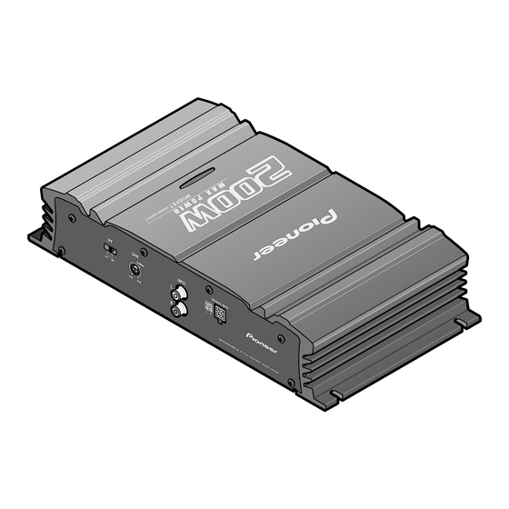
BRIDGEABLE POWER AMPLIFIER
GM-3000T
GM-3000T
GM-3000T
For details, refer to "Important symbols for good services".
PIONEER CORPORATION
PIONEER ELECTRONICS (USA) INC.
PIONEER EUROPE NV
Haven 1087 Keetberglaan 1, 9120 Melsele, Belgium
PIONEER ELECTRONICS ASIACENTRE PTE.LTD. 253 Alexandra Road, #04-01, Singapore 159936
C PIONEER CORPORATION 2004
GM-3000T/X1H/EW
/X1H/UC
/X1H/ES
4-1, Meguro 1-Chome, Meguro-ku, Tokyo 153-8654, Japan
P.O.Box 1760, Long Beach, CA 90801-1760 U.S.A.
/X1H/EW
K-ZZB. JUNE 2004 Printed in Japan
ORDER NO.
CRT3239
Advertisement
Table of Contents

Related Manuals for Pioneer GM3000


Summary of Contents for Pioneer GM3000
- Page 1 PIONEER ELECTRONICS (USA) INC. P.O.Box 1760, Long Beach, CA 90801-1760 U.S.A. PIONEER EUROPE NV Haven 1087 Keetberglaan 1, 9120 Melsele, Belgium PIONEER ELECTRONICS ASIACENTRE PTE.LTD. 253 Alexandra Road, #04-01, Singapore 159936 C PIONEER CORPORATION 2004 K-ZZB. JUNE 2004 Printed in Japan...
-
Page 2: Safety Information
SAFETY INFORMATION UC model CAUTION This service manual is intended for qualified service technicians; it is not meant for the casual do-it-yourselfer. Qualified technicians have the necessary test equipment and tools, and have been trained to properly and safely repair complex products such as those covered by this manual. -
Page 3: Table Of Contents
CONTENTS SAFETY INFORMATION..........2 5. ELECTRICAL PARTS LIST........14 1. SPECIFICATIONS ............3 6. ADJUSTMENT ............16 2. EXPLODED VIEWS AND PARTS LIST ......4 7. GENERAL INFORMATION........17 2.1 PACKING..............4 7.1 DIAGNOSIS ............17 2.2 EXTERIOR ............6 7.1.1 DISASSEMBLY.........17 3. SCHEMATIC DIAGRAM..........8 7.1.2 ..18 CONNECTOR FUNCTION DESCRIPTION 3.1 OVERALL CONNECTION DIAGRAM....8 8. -
Page 4: Exploded Views And Parts List
2. EXPLODED VIEWS AND PARTS LIST 2.1 PACKING GM-3000T/X1H/EW... - Page 5 NOTE: - Parts marked by “*” are generally unavailable because they are not in our Master Spare Parts List. - Screws adjacent to ∇ mark on the product are used for disassembly. - For the applying amount of lubricants or glue, follow the instructions in this manual. ( In the case of no amount instructions, apply as you think it appropriate.) - PACKING SECTION PARTS LIST Part No.
-
Page 6: Exterior
2.2 EXTERIOR GM-3000T/X1H/EW... - Page 7 - EXTERIOR SECTION PARTS LIST Mark No. Description Part No. 1 Screw BBZ30P050FTC 2 Screw BBZ30P060FTC 3 Screw BBZ30P080FTC 4 Screw BBZ30P120FTC 5 Screw BMZ30P050FTC 6 Screw BSZ30P050FTC 7 Screw BSZ30P050FZK 8 Screw(M3x8) HBA0011 9 Screw(M3) HBA0028 10 Stud HLA0022 11 Case HNB0131 12 Panel...
-
Page 8: Schematic Diagram
3. SCHEMATIC DIAGRAM 3.1 OVERALL CONNECTION DIAGRAM Note: When ordering service parts, be sure to refer to " EXPLODED VIEWS AND PARTS LIST" or "ELECTRICAL PARTS LIST". GM-3000T/X1H/EW... - Page 9 NOTE : The > mark found on some component parts indicates Symbol indicates a resistor. Decimal points for resistor the importance of the safety factor of the part. No differentiation is made between chip resistors and and capacitor fixed values Therefore, when replacing, be sure to use parts of discrete resistors.
-
Page 10: Pcb Connection Diagram
4. PCB CONNECTION DIAGRAM 4.1 AMP UNIT NOTE FOR PCB DIAGRAMS AMP UNIT 1.The parts mounted on this PCB include all necessary parts for several destination. For further information for respective destinations, be sure to check with the schematic dia- gram. - Page 11 SIDE A GM-3000T/X1H/EW...
- Page 12 AMP UNIT GM-3000T/X1H/EW...
- Page 13 SIDE B GM-3000T/X1H/EW...
-
Page 14: Electrical Parts List
5. ELECTRICAL PARTS LIST NOTE: - Parts whose parts numbers are omitted are subject to being not supplied. - The part numbers shown below indicate chip components. Chip Resistor RS1/_S___J,RS1/__S___J Chip Capacitor (except for CQS..) CKS.., CCS.., CSZS..=====Circuit Symbol and No.===Part Name Part No. - Page 15 =====Circuit Symbol and No.===Part Name Part No. =====Circuit Symbol and No.===Part Name Part No. ------ ------------------------------------------ ------------------------- ------ ------------------------------------------ ------------------------- RS1/10S153J RN1/10SE2201D RS1/10S153J RS1/10S683J RD1/4PU561J RS1/10S683J RD1/4PU561J RD1/4PU103J RD1/4PU161J RS1/10S473J RD1/4PU161J RS1/10S102J RD1/4PU473J RS1/10S153J RD1/4PU473J (EW,ES) RS1/10S105J RD1/4PU221J RD1/4PU101J RD1/4PU562J RD1/4PU332J RD1/4PU222J RD1/4PU101J...
-
Page 16: Adjustment
=====Circuit Symbol and No.===Part Name Part No. =====Circuit Symbol and No.===Part Name Part No. ------ ------------------------------------------ ------------------------- ------ ------------------------------------------ ------------------------- CKSQYB103K50 CFTNA224J50 CKSQYB103K50 CEAT100M16 CEAT100M16 CEAT221M10 CEAT100M16 CQMA102J50 CEAT470M16 CEAT2R2M50 CKSQYB103K50 CEAT100M16 CEAT220M16 3300µF/16V HCH0005 470µF/16V CCH1183 CQMA472J50 CKSQYB103K50 CQMA472J50 CQMA103J50 CQMA102J50 CEAT2R2M50... -
Page 17: General Information
7. GENERAL INFORMATION 7.1 DIAGNOSIS 7.1.1 DISASSEMBLY Removing the Case (Fig.1) Remove the three screws. Remove the four screws and then remove the Case. Case Fig.1 Removing the Amp Unit (Fig.2) Remove the six screws and then remove the Panel. Remove the screw. -
Page 18: Connector Function Description
7.1.2 CONNECTOR FUNCTION DESCRIPTION GM-3000T/X1H/EW... -
Page 19: Operations
8. OPERATIONS GM-3000T/X1H/EW...
Need help?
Do you have a question about the GM3000 and is the answer not in the manual?
Questions and answers