Table of Contents
Advertisement
Quick Links
Advertisement
Table of Contents

Related Manuals for Elife UNIDRIVE H Series

Summary of Contents for Elife UNIDRIVE H Series
- Page 1 Brushless Edition - Rev. B UNIDRIVE H Series Application Reference Manual...
- Page 2 Tel: +39 0565 944121 Fax: +39 0565 945726 email: info@elifeinternational.com This manual is copyrighted of Elife International. All rights are reserved. This manual must not be copied in whole or in part, nor transferred to any other media or language, without express written permission of Elife International.
-
Page 3: Table Of Contents
Contents 1 Overview 2 Installation and Wiring 2.1 Mounting UNIDRIVE on-board ..... 2.2 Connections ....... . 2.2.1 High Power Connections . - Page 4 The common features of all models of UNIDRIVE H Series ..An overview of the UNIDRIVE H Series Models ... . . A summary table of high-power connections, except the H4896-6-X Type. 7 Fuse size in accordance with the UNIDRIVE Type.
-
Page 5: Overview
Integrated Fuse Holder (only up 80 V) • European Conformity , and designed and tested in accordance with the Electromagnetic compatibility (EMC) emission [EN 61000-6-4] and immunity [EN 61000-6-2] standards. ® Elife International is a Member of CiA - CAN in Automation... -
Page 6: The Common Features Of All Models Of Unidrive H Series
Two High Powered Digital Outputs One 12-bit Analog Input 0 ÷ 10 V Five Digital Inputs Single Ended Four Digital Outputs Singled Ended The common features of all models of UNIDRIVE H Series Table 1.1: ALUE PWM Operating Frequency: 6103 Hz... -
Page 7: An Overview Of The Unidrive H Series Models
A broad range of models enable us to satisfy every requirements and to suggest the best solution for your system. An overview of the UNIDRIVE H Series Models is shown in Table 1.2. For other models, have a look at UNIDRIVE S Series for lower power models or at UNIDRIVE M Series for higher power models. -
Page 8: Product Identification Label
00000143 S/N: Customer Code UNIQUELY CODE IDENTIFIES Portoferraio - ITALY YOU AS A ELIFE IDENTIFIES YOUR UNIDRIVE CUSTOMER www.elifeinternational.com Compliance with the EU regulatory requirement for electrical and electronic equipment. When your UNIDRIVE is no more usable, can’t be treated as generic garbage, but... -
Page 9: Installation And Wiring
Installation and Wiring Mounting UNIDRIVE on-board The UNIDRIVE can be mounted in any orientation, but you must choose a location in order to keep the controller clean and dry, aways from sunlight, water and ice. When you mount the UNIDRIVE on-board you should ensure an effective heat dissipation between the UNIDRIVE and the vehicle surface. -
Page 10: High Power Connections
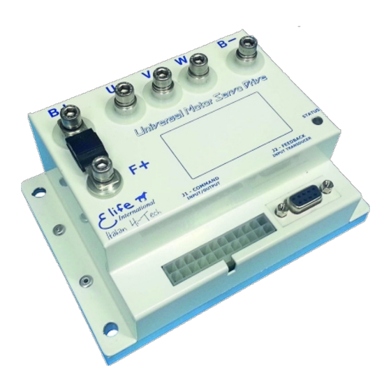
Feedback Connections J2 - FEEDBACK A 9-pin female low power connector ( ) to connect your feedback board. UNIDRIVE has different types of connectors that can be categorized in: High Figure 2.1: J1 - COMMAND ) and Power Connections (U,V,W,F+,B-,B+), Low Power Connections ( J2 - FEEDBACK Feedback Connector ( 2.2.1... -
Page 11: A Summary Table Of High-Power Connections, Except The H4896-6-X Type. 7 2.2 Fuse Size In Accordance With The Unidrive Type
Fuse size in accordance with the UNIDRIVE Type. Table 2.2: UNIDRIVE T ATING H2448-2 100 A H2424-3 100 A H2436-3 70 A H2448-3 50 A H4896-6 70 A UNIDRIVE H Series - High-power connections. Figure 2.2: Connections... -
Page 12: Low Power Connections
2.2.2 Low Power Connections The low power logic control connections are provided by a 24-pin male connector J1 - COMMAND ). The pins’ description is given in Table 2.3. J1 - COMMAND connector. Table 2.3: The pins’ description for the I/O T ESCRIPTION PERATING... - Page 13 . . . continued from previous page I/O T ESCRIPTION PERATING ANGE Analog Common / ANALOG GND Potentiometer Low Input CAN- Standard CAN CAN_L bus line (dominant low) TX output, it is used to TX RS232 Standard RS232 communicate with RS232 in order to realize Telemetry panel RS232 Common, it is used to SERIAL GND...
-
Page 14: Operating Range
. . . continued from previous page I/O T ESCRIPTION PERATING ANGE RX Input, it is used to RX RS232 Standard RS232 communicate with RS232 in order to realize Telemetry panel Concluded Note The digital inputs have over-voltage protection up to battery voltage. Chapter 2 Installation and Wiring... -
Page 15: Standard Wiring Diagrams And Wiring Instructions
Standard Wiring Diagrams and Wiring Instructions This section contains standard wiring diagrams to be used to connect your UNIDRIVE H Series on your system. The following wiring diagrams cover only the standard operating mode in which the UNIDRIVE works to drive a Brushless Servomotor. It’s also possible to connect two or more UNIDRIVE together for specific application (e.g: steering wheel control) and drive different types of servomotor. -
Page 16: Unidrive I/O Definitions For Standalone Mode
UNIDRIVE I/O definitions for Standalone Mode. Table 2.4: ESCRIPTION High = Unlocked, Low = Locked. HANDBRAKE Optional This input is processed only before bridge activation High = Slow mode, Low = Fast mode. FAST/SLOW Optional This input is processed only before bridge activation High = Forward, Low = Stop FORWARD... - Page 17 Vbatt → 24Vout @ 6A VENDOR SPECIFIC BATTERY 24 to 48V The wiring diagram to connect your UNIDRIVE H Series - except the H4896-6-x Figure 2.3: Type - to your system in Standalone Mode. Standard Wiring Diagrams and Wiring Instructions...
- Page 18 Standalone Mode - Wiring Diagram [H4896-6-x Type] OPTIONAL SIGNAL CONNECTIONS RS232-2 TX 1A DELAYED RS232-2 RX 4A DELAYED RS232-2 GND HANDBRAKE 1A DELAYED FORWARD FAST/SLOW BACKWARD EMERGENCY Alternative: use a voltage source in place of the pot. UNIDRIVE H4896-x REVERSE STATUS ALARM BRAKE 24V...
-
Page 19: Plc Mode
2.3.2 PLC Mode The PLC mode is a flexible, self-contained operating mode for automatic vehicles (AGV). The details of inputs and output of this operating mode are shown in Table 2.5. Table 2.5: UNIDRIVE I/O definitions for PLC Mode ESCRIPTION High = Active Overtravel for CCW Optional rotation, Low = Inactive Overtravel... - Page 20 DC / DC Vbatt → 24Vout @ 6A VENDOR SPECIFIC BATTERY 24 to 48V Figure 2.5: The wiring diagram to connect your UNIDRIVE H Series - except the H4896-6-x Type - to your system in PLC Mode. Chapter 2 Installation and Wiring...
- Page 21 PLC Mode - Wiring Diagram [H4896-6-x Type] OPTIONAL SIGNAL CONNECTIONS 1A DELAYED RS232-2 TX RS232-2 RX 4A DELAYED RS232-2 GND 1A DELAYED RUN / STOP EMERGENCY CAN- ANALOG INPUT CAN+ ANALOG GND UNIDRIVE See manual for details H4896-x ALARM MOTOR SPEED REPEATER BRAKE 24V CONTACTOR 24V POWER...
-
Page 22: Input Configuration
In this configuration it is also possible to read the most important information through CAN bus. In this case the IN4 and IN5 input could be used as shown in Table 2.6. CAN bus address selector switch at the node set to 0. Table 2.6: I/O T ESCRIPTION... -
Page 23: Can Network Mode
2.3.3 CAN Network Mode ® In CAN Network mode you can control your motor through CANopen bus protocol. ® ® For further information about CANopen protocol, please refer to CiA DSP402 ® protocol (version 3.0.1.15) and UNDRIVE CANopen Manual. A description of the inputs and outputs connections for this operating mode is shown in Table 2.7 Table 2.7: UNIDRIVE I/O definitions for Can Network Mode... - Page 24 DC / DC Vbatt → 24Vout @ 6A VENDOR SPECIFIC BATTERY 24 to 48V The wiring diagram to connect your UNIDRIVE H Series - except the H4896-6-x Figure 2.7: Type - to your system in CAN Network. Chapter 2 Installation and Wiring...
- Page 25 CAN Network Mode - Wiring Diagram [H4896-6-x Type] OPTIONAL SIGNAL CONNECTIONS RS232-2 TX 1A DELAYED RS232-2 RX 4A DELAYED RS232-2 GND CAN ADDRESS ADR1 ADR0 NODE ADR0 OPEN OPEN ADR1 OPEN +24V CAN- +24V OPEN +24V +24V Note: CAN+ CAN ADDRESS can be also set by telemetry panel from Node 1 to 127 UNIDRIVE H4896-x...
-
Page 26: Rs232 Mode
® Please pay particular attention when wiring CANopen connection: at both ends there must be a 120Ω resistor and the bus length must be the following: IT RATE US LENGTH 1 Mbit/s 25 m 500 Kbit/s 100 m 250 Kbit/s 250 m 125 Kbit/s 100 m... - Page 27 Vbatt → 24Vout @ 6A VENDOR SPECIFIC BATTERY 24 to 48V The wiring diagram to connect your UNIDRIVE H Series - except the H4896-6-x Figure 2.9: Type - to your system in RS232 Mode Standard Wiring Diagrams and Wiring Instructions...
- Page 28 RS232 Mode - Wiring Diagram [H4896-6-x Type] SIGNAL CONNECTIONS RS232-2 TX 1A DELAYED RS232-2 RX 4A DELAYED RS232-2 GND EMERGENCY 1A DELAYED UNIDRIVE H4896-x MOTOR SPEED REPEATER BRAKE 24V CONTACTOR 24V POWER CONNECTIONS MAIN FUSE +OUT -OUT DC / DC Vbatt →...
-
Page 29: Feedback Connector
Feedback Connector J2 - FEEDBACK A female 9-pin connector ( ) is provided to connect the feedback board to the UNIDRIVE (See Figure 2.11). J2 - FEEDBACK Pin Assignments of the connector. Figure 2.11: Note J2 - FEEDBACK The pinout descriptions of connector depends on the type of feedback board mounted on your motor. -
Page 30: Resolver
2.4.1 Resolver J2 - FEEDBACK connector (See Figure 2.11) to Pinout Description of the Table 2.9: connect a Resolver to your UNIDRIVE. PERATING I/O T ESCRIPTION ANGE DRIVING From -5 to +5 V Mandatory The negative Driving signal SIGNAL - THERMAL Optional Temperature sensor... -
Page 31: Sincos Encoder
2.4.2 SinCos Encoder J2 - FEEDBACK connector (See Figure 2.11) to Pinout Description of the Table 2.10: connect a SinCos Encoder to your UNIDRIVE. PERATING I/O T ESCRIPTION ANGE +5 V V = +5 V Mandatory SinCos Supply From -5 to +5 V Mandatory Sine Signal From -5 to +5 V... -
Page 33: Configuration
Configuration This chapter covers what you need to know to configure your UNIDRIVER H Series via Telemetry Panel. Warning This part of the manual assumes that UNIDRIVE was wired up correctly by following methods described in Chapter 2. Telemetry Panel allows the adjustment of a wide range of parameters through the USB port in order to customize the vehicle’s performance characteristics. -
Page 34: Connect Unidrive To Your Pc
Autotuning The gain parameters for closed-loop current control and offset value of Resolver/SinCos can be estimated in Autotuning tab. Car EV Mode Only activated for UNIDRIVE M Series. It will not be dealt with in the present manual. Steering Mode Steering Mode is an advanced operating mode of UNIDRIVE. -
Page 35: Change Programmable Parameters
When the progress bar is running, Telemetry Panel downloads data from .cfg Figure 3.2: file to UNIDRIVE. • In oder to import parameters from file and download them on to UNIDRIVE: Move to Programmable Parameters tab. Select the File Menu and click on Open option. Select the desired .cfg file and wait for the progress bar to get completely green (Figure 3.2). -
Page 36: Operating Mode And Controller Parameters
Programmable Parameters tab allows you to read and change the main Figure 3.3: programmable parameters and set the operating mode. In Programmable Parameters tab (Figure 3.3) you can read and change the main programmable parameters and set the operating mode of UNIDRIVE (Standalone,PLC,etc). After connecting your UNIDRIVE to PC and stopping the motor, the values can be changed in Programmable Parameters tab. - Page 37 Note The gain parameters for closed-loop position control will only processed ® if configuration is CANopen and mode of operation is Interpolated Position Mode. Speed closed loop This text box is only valid for DC motor. Feedback inversion This text box is only valid for DC motor. Encoder inversion This text box is only valid for DC motor.
-
Page 38: Motor And Acceleration Parameters
3.4.2 Motor and Acceleration Parameters Up slope Lower values indicate a longer acceleration time and a more gradual departure, while bigger values indicate a faster acceleration. The implemented ® ramp is linear. This parameter is also programmable by CANopen protocol. ALUE ALUE 35 ·... -
Page 39: Canopen ® Parameters
ALUE ESCRIPTION Direction inversion is realized through direction digital input 0 - 10 (DIR/FORWARD). When the potentiometer value is between 5 and 10 V speed reference is 0-5 - 10 positive. When it is less than 5 V speed reference is negative. Direction inversion is realized through direction digital input 0 - 5 (DIR/FORWARD) -
Page 40: Locked Parameters
Note ® The CANopen values will only processed if UNIDRIVE works in CAN Network or PLC configuration. 3.4.5 Locked Parameters In Programmable Parameters tab there are a few programmable parameters which their text-boxes are disabled but filled with a value (Figure 3.4). You can unlock them and change their value. -
Page 41: Max Value
Parameters Figure 3.4: Programmable there some parameters locked. You can unlocked them after clicking on Change Locked Parameters button. parameter indicates the phase advance angle with respect to back-EMF of phase current. ALUE ALUE a.u. Tips and Advice Motors whose inductance value is high might require a high value of phase advance angle. - Page 42 intervenes only after one minute from brake activation. Its value must be less than 50%. Resolver/SinCos offset This parameter is only valid for Motor with Resolver or SinCos Encoder. Offset to sum to resolver/encoder position. ALUE ALUE 359.99 degree Tips and Advice Resolver/SinCos offset value can be calculated by using Telemetry Panel.
-
Page 43: Advanced Parameters
Back-EMF sample period This text box is only valid for DC motor. This text box is only valid for DC motor. 3.4.6 Advanced Parameters Adavanced tab allows you to read and change some more programmable parameters (Figure 3.5). firmware version, serial number, Some information about UNIDRIVE - such as ®... - Page 44 If emergency input fault is ON, when emergency input gets low motor will stop with alarm; otherwise motor will only stop with ramp. Alarm output N.L. logic This textbox is disabled for UNIDRIVE H Series in standard operating mode. Emergency Slope This parameter configures alarm deceleration, lower values...
- Page 45 Note If KTY83/122 or KTY84/130 is chosen, it will also be possible to read motor temperature from Telemetry tab. Maximum motor temperature At this temperature drive must rise Motor overtemperature alarm. ALUE ALUE ◦ ◦ (32) (491) Encoder resolution This parameter is only available for DC motors. Mechanical reducer This parameter is only available for DC motors.
-
Page 46: Auto-Tuning Unidrive Parameters
Auto-tuning UNIDRIVE Parameters Telemetry Panel includes two functions which help you to estimate approximate value of the following parameters: • The gain parameters for closed-loop current control. • The Offset Resolver/SinCos to sum to resolver/encoder position. Warning Please note that the suggested parameters are only a point of departure. They must be adjusted according to system and you should run the motor only after checking them. -
Page 47: Offset Resolver/Sincos
In Autotuning tab allows Figure 3.6: you to estimate gain parameters for closed-loop current control. 3.5.2 Offset Resolver/SinCos Finding the correct value of Offset Resolver/SinCos is critical to the proper functioning of the system. Telemetry Panel helps you determine the correct value of Offset Resolver/SinCos to sum to resolver/SinCos position: Move to Programmable Parameters tab. - Page 48 In Resolver Autotuning panel you can see two LED indicators: Resolver state This alarm indicates that resolver cable isn’t connected or that resolver is broken. If led is red, it won’t be possible to accomplish resolver autotuning. Brake state This led reflects the brake setting: when brake is locked led is green, when unlocked led is yellow.
-
Page 49: Monitoring Unidrive
Monitoring UNIDRIVE After wiring up correctly UNIDRIVE (See Chapter 2) and adjusting the programmable parameters (See Chapter 3), you are finally ready to test your system. Warning Before starting the test, you had better lift your vehicle up. The driving wheels must be off the ground and free to rotate. - Page 50 Tips and Advice In order to test your device for the first time, we suggest to select RS232 (in Speed or Torque mode) as Configuration in Programmable Parameters tab. So you will be able to manually set the target velocity of your motor (See Section 2.3.4 and Section 4.2.4).
- Page 51 Telemetry Panel displays a wide range of telemetry data and enables you to plot Figure 4.1: or log these data over time. Reading Telemetry Data from Telemetry Panel...
-
Page 52: Alarm Indicators
Analog input 2 It’s only displayed for UNIDRIVE M Series. Output Power It shows the relative electrical output power. Actual position It shows the actual of position control closed-loop. This parameter is processed only for CAN Network configuration when the operational mode is Interpolated position mode. -
Page 53: Reset All Current Alarms
Communication timeout This alarm happens when configuration is Steering and driver measure a communication timeout. Feedback This alarm indicates that the feedback cable isn’t properly connected or that the feedback is broken. Overcurrent It happens whenever one of the modules of three current phases is higher than a threshold. -
Page 54: Digital I/O And Drive State Indicators
Tips and Advice It’s also possible to reset all running alarms with a rising edge signal (transition from low to high) at the P 15 (RUN / STOP) in Standalone and PLC configuration and with a fault reset command if you employ CAN telemetry protocol. -
Page 55: The Target Velocity/Torque Track Bar
TATUS EANING Green The relay is enabled Yellow The relay is disabled Power supply relay failure Tips and Advice If you get this alarm only when you give RUN command, this behavior is probably due to a Resolver problem (See Appendix A and read the Feedback Alarm troubleshooting). -
Page 56: Plot And Log Telemetry Data In Real-Time
This track bar allows you to manually set the target velocity - or torque - value of your Motor from 0 to the Max value that you have set as the Max motor Speed (See Section 3.4.2). The sign of value determine the direction of rotation: ALUE IRECTION OF OTATION... -
Page 57: Plotting And Logging Telemetry Data With Telemetry Panel
Plotting and logging telemetry data with Telemetry Panel. Table 4.2: UTTON UNCTION UTTON UNCTION Play Button Pause Button Start to plot telemetry data Stop plotting telemetry data Save Button Stop Button Start to log telemetry data Stop collecting telemetry data Select one or more (max four) telemetry data that you’ll want to observe from TRACE 1, TRACE 2,TRACE 3 or TRACE 4 list (Figure 4.3). -
Page 59: Maintenance
UNDRIVE. You can read these messages in one of the following ways: Diagnostic Display Elife Diagnostic Display allows you to get some information about battery - autonomy and voltage - and UNIDRIVE fault codes. Telemetry Panel Telemetry Panel enables you to control your UNIDRIVE and read a wide range of telemetry data (See Chapter 4). -
Page 61: Troubleshooting: Alarm Messages
This section covers only the common and likely causes of alarm messages and actions that should be taken by the operator. UNIDRIVE alarms can be interpreted using the Telemetry Panel (See Chapter 5), Elife Diagnostic Display ® or can be read through the CanOpen Protocol also. - Page 62 Following Alarm DESCRIPTION This kind of alarm happens when the detected speed is less than 80% or more than 120% over the set time period (See Section 3.4.6). UNIDRIVE BEHAVIOUR UNIDRIVE stops motor rotation with emergency slope (disabling power relay and three-phase bridge) and unlocks motor brake. POSSIBLE TROUBLESHOOTING ISSUE There are two possible reasons for this alarm: the phase current isn’t sufficient to accomplish operation or your motor is...
- Page 63 Communication timeout Alarm DESCRIPTION This alarm happens when configuration is Steering and master measure a communication timeout. UNIDRIVE BEHAVIOUR UNIDRIVE stops motor rotation with emergency slope (disabling power relay and three-phase bridge) and unlocks motor brake. POSSIBLE TROUBLESHOOTING ISSUE Check configuration and wiring between the UNIDRIVE and master (See UNIDRIVE - Steering Mode Manual).
-
Page 64: Overcurrent Alarm
If these checks failed, you must: Check the correct connection between motor housing appropriate terminal and driver negative terminal (-). Check electrical isolation between every phase and motor housing. Pass feedback cable as far as possible from power cables. Check the correct Resolver/SinCos installation within motor. Overcurrent Alarm DESCRIPTION It happens whenever one of the modules of three current phases is... -
Page 65: Overvoltage Alarm
Overvoltage Alarm DESCRIPTION This error is showed when bus voltage is higher than 80 V for 24 ÷ 48 models and 122 V for 48 ÷ 96 models. UNIDRIVE BEHAVIOUR UNIDRIVE stops motor rotation with emergency slope (disabling power relay and three-phase bridge) and unlocks motor brake. POSSIBLE TROUBLESHOOTING ISSUE There are two possible explanation for this alarm:... - Page 66 Motor overtemperature Alarm DESCRIPTION This alarm appears when: • Motor temperature exceeds Maximum motor temperature value if set Temperature probe type is KTY83/122 or KTY84/130. • Motor temperature sensor isn’t connected if Thermostat is selected as Temperature probe type. UNIDRIVE BEHAVIOUR UNIDRIVE stops motor rotation with emergency slope (disabling power relay and three-phase bridge) and unlocks motor brake.
-
Page 67: Operating Range
Index of Programmable Parameters Index of UNIDRIVE Programmable Parameters in alphabetical order. Table B.1: PERATING ANGE ROGRAMMABLE EFERENCE ® by C UNIT allowed values Pag. 35 Analogic input Brake current Pag. 37 reduction boolean value Pag. 40 Brake fault alarm ®... - Page 68 . . . continued from previous page PERATING ANGE ROGRAMMABLE EFERENCE ® UNIT by C °C Maximum motor Pag. 41 temperature (32) (491) (°F) Amperes • Maximum phase Pag. 37 current integer Pag. 36 Motor poles boolean value Pag. 33 NH Alarm Output boolean value Pag.
- Page 70 © Elife International 2016 www.elifeinternational.com...
Need help?
Do you have a question about the UNIDRIVE H Series and is the answer not in the manual?
Questions and answers