
Related Manuals for Elife Elife-Drive HR Series

Summary of Contents for Elife Elife-Drive HR Series
- Page 1 Brushless Edition - Rev. B Elife-Drive HR Series (ex H) Application Reference Manual...
- Page 2 Tel: +39 0565 944121 Fax: +39 0565 945726 email: info@elifeinternational.com This manual is copyrighted of Elife International. All rights are reserved. This manual must not be copied in whole or in part, nor transferred to any other media or language, without express written permission of Elife International.
-
Page 3: Table Of Contents
3.1 Software Overview ......33 3.2 Connect Elife-Drive to your PC ..... 34 3.3 Import and Export Parameter Values . - Page 4 Elife-Drive I/O definitions for Standalone Mode... . . 12 Elife-Drive I/O definitions for PLC Mode ....16 CAN bus address selector switch at the node set to 0.
- Page 5 Plotting and logging telemetry data with Telemetry Panel..60 Index of Elife-Drive Programmable Parameters in alphabetical order. .
-
Page 7: Overview
Overview Elife-Drive is the new family of drivers designed to drive the various types of low-voltage servomotors, specifically for use in battery powered devices. The compact form was made possible thanks to the high efficiency of the design, manufactured with state-of-art electronic components. -
Page 8: The Common Features Of All Models Of Elife-Drive H Series
Two High Powered Digital Outputs One 12-bit Analog Input 0 10 V Five Digital Inputs Single Ended Four Digital Outputs Singled Ended The common features of all models of Elife-Drive H Series Table 1.1: ALUE PWM Operating Frequency: 6103 Hz... -
Page 9: An Overview Of The Elife-Drive H Series Models
A broad range of models enable us to satisfy every requirements and to suggest the best solution for your system. An overview of the Elife-Drive H Series Models is shown in Table 1.2. For other models, have a look at Elife-Drive S Series for lower power models or at Elife-Drive M Series for higher power models. - Page 10 Most of information about your Elife-Drive - such as serial number, model, customer information, etc - can be found on a label located on the front of the Elife-Drive (see figure below). Some of these information might be requested when you contact the technical assistance.
-
Page 11: Installation And Wiring
Elife-Drive and the vehicle surface. Elife-Drive has a LED light on the front of the device that visually explains what the driver is doing (see Section 4.1), if you want it to be visible you should take this into consideration before choosing the location where your Elife-Drive will be mounted. -
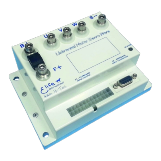
Page 12: High Power Connections
A 9-pin female low power connector ( ) to connect your feedback board. Figure 2.1: Elife-Drive has different types of connectors that can be categorized in: High J1 - COMMAND ) and Power Connections (U,V,W,F+,B-,B+), Low Power Connections ( J2 - FEEDBACK Feedback Connector ( 2.2.1... -
Page 13: A Summary Table Of High-Power Connections, Except The H4896-X-X Type. 7 2.2 Fuse Size In Accordance With The Elife-Drive Type
Make sure when you connect the high-power cables that the feedback cable passes as far as possible from the power cables and they are not located close to each other, in order to avoid electromagnetic interference. Fuse size in accordance with the Elife-Drive Type. Table 2.2: LIFE... -
Page 14: Low Power Connections
2.2.2 Low Power Connections The low power logic control connections are provided by a 24-pin male connector J1 - COMMAND ). The pins’ description is given in Table 2.3. J1 - COMMAND connector. The pins’ description for the Table 2.3: I/O T ESCRIPTION PERATING... - Page 15 . . . continued from previous page I/O T ESCRIPTION PERATING ANGE Analog Common / ANALOG GND Potentiometer Low Input CAN- Standard CAN CAN_L bus line (dominant low) TX output, it is used to TX RS232 Standard RS232 communicate with RS232 in order to realize Telemetry panel RS232 Common, it is used to SERIAL GND...
- Page 16 Note The digital inputs have over-voltage protection up to battery voltage and the analog input up to 26 V. Installation and Wiring Chapter 2...
-
Page 17: Standard Wiring Diagrams And Wiring Instructions
Standard Wiring Diagrams and Wiring Instructions This section contains standard wiring diagrams to be used to connect your Elife-Drive H Series on your system. The following wiring diagrams cover only the standard operating mode in which the Elife-Drive works to drive a Brushless Servomotor. -
Page 18: Elife-Drive I/O Definitions For Standalone Mode
Elife-Drive I/O definitions for Standalone Mode. Table 2.4: ESCRIPTION Rising Edge Signal = Enable/Disable CRUISE Optional Active or Disable the Cruise Control if a Rising Edge Signal is detected High = Slow mode, Low = Fast mode. FAST/SLOW Optional This input is processed only before bridge... - Page 19 A Risign Edge Signal on IN1 If the Emergency Input is unsupplied. For any Alarm Occours. The wiring diagram for standalone mode is shown in Figure 2.3 for any Elife-Drive H Series Type, except the H4896-X-X Type (Figure 2.4). Standard Wiring Diagrams and Wiring Instructions...
- Page 20 DC / DC Vbatt → 24Vout @ 6A VENDOR SPECIFIC BATTERY 24 to 48V The wiring diagram to connect your Elife-Drive H Series - except the H4896-X-X Figure 2.3: Type - to your system in Standalone Mode. Installation and Wiring Chapter 2...
- Page 21 MAIN FUSE -OUT +OUT DC / DC Vbatt → 24Vout @ 6A VENDOR SPECIFIC BATTERY 48V to 96V The wiring diagram to connect your Elife-Drive H4896-X-X to your system in Figure 2.4: Standalone Mode. Standard Wiring Diagrams and Wiring Instructions...
-
Page 22: Plc Mode
The PLC mode is a flexible, self-contained operating mode for automatic vehicles (AGV). The details of inputs and output of this operating mode are shown in Table 2.5. Table 2.5: Elife-Drive I/O definitions for PLC Mode ESCRIPTION High = Active Overtravel for CCW Optional... -
Page 23: Can Bus Address Selector Switch At The Node Set To 0
3.4.6) Elife-Drive will stop the motor when one of two over-travel inputs (CCW OVERTRAVEL and CW OVERTRAVEL) will get high. Otherwise if the overtravels are disabled by the Telemetry panel, the IN1 can be use Cruise Control. to active the Cruise Control. - Page 24 DC / DC Vbatt → 24Vout @ 6A VENDOR SPECIFIC BATTERY 24 to 48V The wiring diagram to connect your Elife-Drive H Series - except the H4896-X-X Figure 2.5: Type - to your system in PLC Mode. Installation and Wiring Chapter 2...
- Page 25 @ 6A VENDOR SPECIFIC BATTERY 48V to 96V The wiring diagram to connect your Elife-Drive H4896-X-X to your system in Figure 2.6: PLC Mode. In the wiring diagram Resolver is used as Feedback System, for other feedback systems see Section 2.4.
-
Page 26: Can Network Mode
CAN address selector inputs (CAN ADR0,CAN ADR1) are ignored to set the CAN Address. The IN5 input becomes an Emegency Input and will must be supplied, otherwise Elife-Drive stops motor rotation and unlocks motor brake In case that the CAN address is set to 0 through Telemetry panel, after switch-on it... - Page 27 → 24V @ 6A batt VENDOR SPECIFIC BATTERY 24 to 48V The wiring diagram to connect your Elife-Drive H Series - except the H4896-X-X Figure 2.7: Type - to your system in CAN Network. Standard Wiring Diagrams and Wiring Instructions...
- Page 28 MAIN FUSE -OUT +OUT DC / DC → 24V @ 6A batt VENDOR SPECIFIC BATTERY 48 to 96V The wiring diagram to connect your Elife-Drive H4896-X-X to your system in Figure 2.8: CAN Network Mode. Installation and Wiring Chapter 2...
- Page 29 CAN N NPUT ONFIGURATION CAN ADR1 CAN ADR0 CAN ADR1 CAN ADR0 +24V CAN ADR1 +24V CAN ADR0 CAN ADR1 +24V CAN ADR0 +24V ® Please pay particular attention when wiring CANopen connection: at both ends there must be a 120Ω resistor and the bus length must be the following: IT RATE US LENGTH 1 Mbit/s...
-
Page 30: Rs232 Mode
Alarm output, it changes its current state OUT3 ALARM whenever an alarm is present. See Section 3.4.1, Pag. 37 For further information, see Elife-Drive - RS232 Communication Protocol document Installation and Wiring Chapter 2... - Page 31 VENDOR SPECIFIC BATTERY 24 to 48V The wiring diagram to connect your Elife-Drive H Series - except the H4896-X-X Figure 2.9: Type - to your system in RS232 Mode. To connect the feedback system see Section 2.4. Standard Wiring Diagrams and Wiring Instructions...
- Page 32 Vbatt → 24Vout @ 6A VENDOR SPECIFIC BATTERY 48V to 96V The wiring diagram to connect your Elife-Drive H4896-X-X to your system in Figure 2.10: RS232 Mode. To connect the feedback system see Section 2.4. Installation and Wiring Chapter 2...
-
Page 33: Feedback Connector
Note J2 - FEEDBACK The pinout descriptions and type of connector depends on the type of feedback board mounted on your motor and the Elife-Drive Type chosen. Connector: A female 9-pin connector used to connect the following Motor Feedback: Resolver: See Section 2.4.1. - Page 34 See Section 2.4.4. Digital Absolute Encoder: SSI or SPI Connection, see Section 2.4.5. J2 - FEEDBACK Pin Assignments of the female connector on Elife-Drive (VGA Figure 2.12: Connector). Warning Make sure when you connect the high-powered connections that the feedback cable passes as far as possible from the power cables, and them are not located close to each other, in order to avoid electromagnetic interference.
-
Page 35: Resolver
FEMALE - VIEW FROM WIRE SIDE 1 9 8 10 12 Wiring Diagram to connect your Resolver board to Elife-Drive if your motor Figure 2.13: has a M23 feedback motor connector (a possible connection). The M23 pins out are specified in the Motor Technical Datasheet. -
Page 36: Sincos Encoder
2.4.2 SinCos Encoder J2 - FEEDBACK DB9 connector (See Figure 2.11) Table 2.10: Pinout Description of the to connect a SinCos Encoder to your Elife-Drive. PERATING I/O T ESCRIPTION ANGE +5 V V = +5 V Mandatory SinCos Supply From 0 to +5 V... -
Page 37: Fa-Coder
2.4.4 Fa-Coder J2 - FEEDBACK VGA connector (See Figure 2.12) Pinout Description of the Table 2.12: to connect a Fa-Coder to your Elife-Drive. PERATING I/O T ESCRIPTION ANGE From 0 to +5 V Mandatory Hall Sensor U From 0 to +5 V... -
Page 38: Digital Absolute Angle Position
(See Pag. 45) In case of SPI Sensor, the DATA signals are also called MISO. Note The Elife-Drive is compatible with a wide range of Motor Feedback that use SSI or SPI as protocol communication. Installation and Wiring Chapter 2... -
Page 39: Configuration
Configuration This chapter covers what you need to know to configure your Elife-Drive MR and MP Series via Telemetry Panel. Warning This part of the manual assumes that Elife-Drive was wired up correctly by following methods described in Chapter 2. -
Page 40: Connect Elife-Drive To Your Pc
Steering Mode manual. Connect Elife-Drive to your PC In order to connect your Elife-Drive to Telemetry Panel, you should connect it to PC and wait for USB port recognition. After USB port recognition, you can launch Telemetry Panel and click on Connection menu (Figure 3.1). -
Page 41: Import And Export Parameter Values
Import and Export Parameter Values After connecting your Elife-Drive to PC you can easily import or export (save) parameter values from and to .cfg file by Telemetry Panel. In oder to import parameters from file and download them on to Elife-Drive: Move to Programmable Parameters tab. -
Page 42: Operating Mode And Controller Parameters
In Programmable Parameters tab (Figure 3.3) you can read and change the main programmable parameters and set the operating mode of Elife-Drive (Standalone,PLC,etc). After connecting your Elife-Drive to PC and stopping the motor, the values can be changed in Programmable Parameters tab. - Page 43 Standalone,CAN Network,PLC and RS232 (in Speed or Torque Mode). Warning Elife-Drive must be wired up correctly according to the operating mode selected. See Chapter 2. Max drive temperature At this drive temperature drive must rise "Drive over-temperature"...
-
Page 44: Motor And Acceleration Parameters
Following error delay When the detected speed is less than 80 % or more than 120 % of the target speed over the set time, Elife-Drive stops the motor with ® following error alarm. This parameter is also programmable by CANopen protocol. -
Page 45: Throttle Parameters
Backward maximum speed Only valid for Elife-Drive M Series. 3.4.3 Throttle Parameters Analogic input This parameter describes the analog operational mode used to process the speed potentiometer. It is processed only for PLC and Standalone. ALUE ESCRIPTION Direction inversion is realized through direction digital input 0 - 10 (DIR/FORWARD). -
Page 46: Locked Parameters
filled with a value (Figure 3.4). You can unlock them and change their value. Warning These parameters are critical for the correct function of Elife-Drive. You should change these parameters carefully and only if necessary. In order to change these parameters: Click on Change Locked Parameters button. - Page 47 Parameters Figure 3.4: Programmable there some parameters locked. You can unlocked them after clicking on Change Locked Parameters button. Tips and Advice The Kp and Ki values can be calculated by using Telemetry Panel. See Section 3.5.1 Motor poles It indicates the number of motor poles and must be taken from motor datasheet.
- Page 48 This parameter is only valid for Hall sensor drive. It must be chosen after precisely setting of phase zero, applying backward direction. ALUE ALUE 359.99 degree The maximum peak output current depends on the Elife-Drive model installed. Configuration Chapter 3...
-
Page 49: Advanced Parameters
Advanced Parameters Adavanced tab allows you to read and change some more programmable parameters (Figure 3.5). firmware version, serial number, Some information about Elife-Drive - such as ® CANopen parameters customer code, etc - and are displayed in this tab. - Page 50 When turned OFF, Elife-Drive won’t stop the motor nor inform about a power supply relay failure. Lower battery dinamic decrease if it turned ON, when the battery is being consumed Elife-Drive decrease automatically the speed in order to extend the battery life. Configuration Chapter 3...
- Page 51 Power control If this option is set ON, Elife-Drive limits the max value of mechanical power of your motor for the nominal power of your Elife-Drive. Feedback Alarm in Stop If this option is set OFF, the Feedback alarm is processed as warning when the Elife-Drive is in stop mode.
-
Page 52: Auto-Tuning Elife-Drive Parameters
Potentiometer Supply This parameter is only available for Elife-Drive M Series. TPD02 transmission type It sets the type of transmission for TPDO2. It’s only ® ® processed if configuration is CANopen and can be programmable by CANopen protocol also. ALUE... -
Page 53: Finding The Min And Max Values For Sincos Encoder
The Telemetry Panel shows you the value of Kp and Ki and gets you some additional information (Cut Frequency, Motor RL Constant, PWM attenuation) which can be useful to tune Kp and Ki parameters. Elife-Drive also suggests you the max value of Slope for acceleration and deceleration ramps (See Section 3.4.2). - Page 54 SinCos Encoder installed (these values depend both the type of SinCos Encoder chosen and from how it’s mounted on the motor). Telemetry Panel automatically send to Elife-Drive the values founded. Configuration Chapter 3...
-
Page 55: Offset Resolver/Sincos
Check that motor runs through Velocity Target trackbar. Note Telemetry Panel will automatically send the new value of Offset Resolver/SinCos calculated to Elife-Drive. In Resolver Autotuning panel you can see two LED indicators: Feedback state This alarm indicates that resolver cable isn’t connected or that resolver is broken. - Page 56 - is valid both star and triangle (or Delta) connection Note The Elife-Drives (XXXXX-7 Series) allow you to set the Excitation amplitude,Input sensitivity and Excitation frequency parameters. This values must be chosen in according to the Resolver Technical Datasheet.
-
Page 57: Monitoring Elife-Drive
All testing and adjustment must be done in safe condition. LED Diagnostics Elife-Drive has an LED light on the front of the device that visually explains what the driver is doing. Below is the explanation of the different LED’s status: Blinking ORANGE... - Page 58 Temperature of Elife-Drive. Motor Temperature This information is available only if Temperature probe type parameter in Advanced tab is KTY83/122 or KTY84/130. In Chapter 3 is explained the details how install and connect your Elife-Drive to PC. Monitoring Elife-Drive Chapter 4...
- Page 59 Figure 4.1: Telemetry Panel displays a wide range of telemetry data and enables you to plot or log these data over time. Reading Telemetry Data from Telemetry Panel...
-
Page 60: Alarm Indicators
Alarm Indicators The Alarm Indicators on Telemetry tab enable you to determine what kind of errors are present. When Elife-Drive detects one or more alarms stops motor rotation (disabling power relay and three-phase bridge) and unlocks motor brake. A green led means that the corresponding alarm isn’t signaled, while a red led means that the alarm is active. - Page 61 This alarm indicates that the feedback cable isn’t properly connected or that the feedback is broken. Tips and Advice By a Popup Window, Elife-Drive shows you additional information about Feedback Alarm. Overcurrent It happens whenever one of the modules of three current phases is higher than a threshold.
-
Page 62: Reset All Current Alarms
Motor temperature sensor isn’t connected if Thermostat is selected as PTC type. Safety It is only displayed for Elife-Drive M Series. Stalled Rotor It’s alarm appears when the motor is blocked and at the same time the phase current is high about for approximately for a second. -
Page 63: Description Of Digital I/O Indicators In Telemetry Panel
Drive status Output 3 Drive alarm Output 4 Encoder emulator Only if "Analog input" is 0-10V or 0-5V. The Drive State Indicators get you some information about the following Elife-Drive state: Power Relay This led reflects the supply relay: TATUS EANING... -
Page 64: The Target Velocity/Torque Track Bar
This function can be useful for testing your motor, without worrying about other devices (e.g: potentiometer) or other controllers (e.g: PLC). You can also put the exact value of desired target velocity/torque on the textbox at the left end of the track bar. Monitoring Elife-Drive Chapter 4... -
Page 65: Plot And Log Telemetry Data In Real-Time
Plot and Log Telemetry Data in Real-Time In telemetry Panel you can also plot telemetry data over time and create a log file to view later in a spreadsheet program. Telemetry Panel allows you to set the following plot parameters: Y-axis Scale Y Max and Y Min set the maximum and minimum value the y-axis of the plot. - Page 66 Start to plot telemetry data Stop plotting telemetry data Save Button Stop Button Start to log telemetry data Stop collecting telemetry data Telemetry Panel allows you to plot and log one or more telemetry data. Figure 4.3: Monitoring Elife-Drive Chapter 4...
-
Page 67: Maintenance
Maintenance Elife-Drive no needs any maintenance interventions. It’s only necessary to keep the contacts and the controller clean and dry. The fuse is the only user-serviceable part in the Elife-Drive (See Table 2.2, Pag. 7). Warning Never attempt to disassemble, repair, or modify the Elife-Drive yourself, penalty the voiding of the warranty rules. -
Page 69: A Troubleshooting: Alarm Messages
Troubleshooting: Alarm Messages This section covers only the common and likely causes of alarm messages and actions that should be taken by the operator. Elife-Drive alarms can be interpreted using the Telemetry Panel (See Chapter 5), Elife Diagnostic Display ®... - Page 70 POSSIBLE TROUBLESHOOTING ISSUE Restore drive temperature conditions, then reset alarms. If the error appears frequently, you must improve heat exchange between the Elife-Drive and the vehicle surface (See Section 2.1). Troubleshooting: Alarm Messages Chapter A...
- Page 71 POSSIBLE TROUBLESHOOTING ISSUE Check configuration and wiring between the Elife-Drive and master (See Elife-Drive - Steering Mode Manual). Feedback Alarm DESCRIPTION The Feedback cable isn’t properly connected or otherwise if this error...
- Page 72 It happens whenever one of the modules of three current phases is higher than a threshold. Elife-Drive BEHAVIOUR Elife-Drive stops motor rotation with emergency slope (disabling power relay and three-phase bridge) and unlocks motor brake. POSSIBLE TROUBLESHOOTING ISSUE The possible actions that should be taken: Check the proper functioning of the feedback system.
- Page 73 POSSIBLE TROUBLESHOOTING ISSUE There are two possible explanation for this alarm: Battery voltage, or battery charging voltage, is too high for the Elife-Drive Type installed. The voltage generated by your motor, when is in generator mode, is higher than the battery voltage: Change your battery system or decrease the Max motor speed value (See Section 3.4.2).
- Page 74 It is processed only for PLC and Standalone configurations. Elife-Drive BEHAVIOUR When motor is rotating, if analog input cable will disconnect or break during run operation, Elife-Drive stops motor rotation with emergency slope (disabling power relay and three-phase bridge) and unlocks motor brake. POSSIBLE TROUBLESHOOTING ISSUE...
- Page 75 After switch on, drive won’t enable power relay and three-phase bridge. POSSIBLE TROUBLESHOOTING ISSUE The possible actions that should be taken: Check the integrity of the fuse. If this error appears always when you run Elife-Drive, contact the technical assistance.
-
Page 77: B Index Of Programmable Parameters
Index of Programmable Parameters Index of Elife-Drive Programmable Parameters in alphabetical order. Table B.1: PERATING ANGE ROGRAMMABLE EFERENCE ® UNIT by C allowed values Pag. 39 Analogic input Brake current Pag. 42 reduction boolean value Pag. 44 Brake fault alarm ®... - Page 78 . . . continued from previous page PERATING ANGE ROGRAMMABLE EFERENCE ® UNIT by C Amperes • Maximum phase Pag. 42 current Pag. 41 Motor poles integer boolean value Pag. 37 NH Alarm Output Pag. 45 boolean value Overtravel warning Pag.
- Page 80 © Elife International 2018 www.elifeinternational.com...
Need help?
Do you have a question about the Elife-Drive HR Series and is the answer not in the manual?
Questions and answers