
Related Manuals for Condair HumiLife MN


Summary of Contents for Condair HumiLife MN
- Page 1 PLANNING AND INSTALLATION INSTRUCTIONS Condair HumiLife - The flexible room solution Condair MN Humidification, Dehumidification and Evaporative Cooling...
- Page 2 Condair Ltd., except to the extent required for installation or maintenance of recipient's equipment. Liability Notice Condair Ltd. does not accept any liability due to incorrect installation or operation of the equipment or due to the use of parts/components/equipment that are not authorized by Condair Ltd.
-
Page 3: Table Of Contents
Calculating cable and hose lengths Overview of clearances to be observed Information on positioning the central unit and water filter(s) Information on positioning of the components of the optional reverse osmosis system Condair RO-HB Positioning the spray heads Water supply requirements 4.9.1... - Page 4 5.6.1 Drill wall duct(s) 5.6.2 Laying cable ducts Installing the central unit and water filter housing(s) Installing the components of the optional reverse osmosis system Condair RO-HB Setting up water inlet and outlet 5.9.1 Information on water installation 5.9.2 Water installation overview 5.9.3...
-
Page 5: Introduction
First things first! Thank you for choosing the Condair MN. The Condair MN has been built using state-of-the-art technology and in accordance with the latest safety regulations. However, improper installation and use of the Condair MN may put users and/or third parties at risk and may also cause damage to material assets. - Page 6 Keep this documentation in a safe place for further use. If these instructions are lost or if you are unsure whether this documentation is still up to date, please contact your Condair representative. Language versions This documentation is available in various languages. For more information, please contact your Condair representative. Introduction...
-
Page 7: For Your Safety
Furthermore, for safety and warranty reasons, interventions may only be undertaken by specialist personnel authorized by Condair. It is assumed that all persons entrusted to work on the Condair MN are familiar with and abide by the regulations on occupational health and safety and accident prevention. - Page 8 Hazards that may arise from the Condair MN: DANGER! Risk of electrocution The Condair MN's central unit is supplied with line voltage. If the central unit is open, live parts may be touched. Touching live parts may cause severe injury or death.
- Page 9 Preventing hazardous operating conditions If it is suspected that safe operation is no longer possible, the Condair MN should immediately be shut down and secured against accidental power-up. Then, contact the Condair representative. This can be the case under the following circumstances: –...
-
Page 10: Product Overview
The identification of the product is found on the specification label on the right side of the central unit: Production Type designation Serial number (7 digits) Month/Year Condair Ltd., 2740 Fenton Road, Ottawa, Ontario K1T3T7 Supply voltage Type: Condair MN Serial-No: XXXXXXX 02.20 Voltage: 100-240V/1~/50-60Hz Power: max. -
Page 11: System Overviews
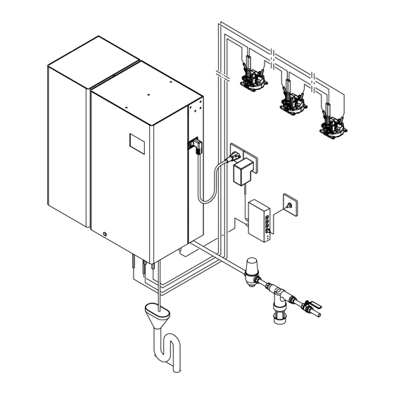
Main power supply receptacles for central unit and LAN gateway (provided on site) LAN connection (provided on site) LAN cable (provided on site) Fig. 2: Overview of Condair MN system with internal drainage of spray circuit 2600432-J EN UL 2411 Product overview... - Page 12 Main power supply receptacles for central unit and LAN gateway (provided on site) CAN bus cable Water hoses Spray heads Fig. 3: Overview Condair MN system with internal drainage of spray circuit and reverse osmosis system Condair RO-HB Product overview 2600432-J EN UL 2411...
- Page 13 Main power supply receptacles for central unit and LAN gateway (provided on site) LAN connection (provided on site) LAN cable (provided on site) Fig. 4: Overview of Condair MN system with external drainage of spray circuit 2600432-J EN UL 2411 Product overview...
- Page 14 Main power supply receptacles for central unit and LAN gateway (provided on site) CAN bus cable Water hoses Spray heads Drain module (mounted externally) Fig. 5: Overview of Condair MN system with external drainage of spray circuit and reverse osmosis system Condair RO-HB Product overview 2600432-J EN UL 2411...
-
Page 15: System Description
5) per spray circuit. The Condair MN system can optionally be equipped with a reverse osmosis system RO-HB (reverse osmosis unit with expansion tank) and a booster module to feed the Condair MN system with RO water (see Fig. 3 Fig. - Page 16 Hygiene functions In order to comply with the guidelines set out in VDI 6022, sheet 6, the Condair MN has the following hygiene functions as standard: – Periodic system flushing – UV treatment of water – Permanent temperature control –...
-
Page 17: Spray Circuit Design
Spray circuit design Room 2 Room 3 Room 2 Room 3 Room 4 Room 1 Zone 5 Zone 3 Zone 2 Zone 4 Room 1 Room 4 Bathroom Kitchen Kitchen Bathroom Zone 1 Zone 6 CU: Central unit 1x CAN bus cable SH: Spray head 1x hose DM: Drain module (external drainage) -
Page 18: Options
Options Second water filter in housing Second water filter to prolong the interval between filter replacements. Water filter without housing Water filter without housing for placing on the ground. Serves as an alternative to the first and/or second water filter if there is no room to attach the water filter in the housing at the installation site. - Page 19 Reverse osmosis system RO-HB Reverse osmosis system RO-HB consisting of the reverse osmosis unit Condair RO-H and the 12 l expansion tank for feeding the central unit with RO water. Note: A booster module is additionally required to operate the Condair MN system with the RO-HB reverse osmosis system.
-
Page 20: Planning A Condair Mn System
Planning a Condair MN system Note on the water supply to the Condair MN The Condair MN can be operated with raw water (drinking water) or with RO water from the reverse osmosis system Condair RO-HB. For larger systems or systems with a high number of operating days and/or with a high number of op- erating hours per day, the use of the reverse osmosis system RO-HB for the treatment of the supply water must be considered. -
Page 21: Calculating Cable And Hose Lengths
262 ft (80 m) 58.0 psig (400 kPa) up to 328 ft (100 m) 65.3 psig (450 kP) up to 361 ft (110 m) 72.5 psig (500 kPa) up to 394 ft (120 m) 2600432-J EN UL 2411 Planning a Condair MN system... -
Page 22: Overview Of Clearances To Be Observed
. 6 " Fig. 7: Overview of clearances to be observed (dimensions in inch (mm)) Note: Detailed information on the placement of the individual components can be found in Section 4.6 Section 4.8. Planning a Condair MN system 2600432-J EN UL 2411... -
Page 23: Information On Positioning The Central Unit And Water Filter(S)
0.8" (20) Ensure sufficient space (min. 11.8" (min. 300 mm)) 6.1" (156) to position the drain funnel with trap Fig. 8: Central unit and water filter dimensions (dimensions in inch (mm)) 2600432-J EN UL 2411 Planning a Condair MN system... -
Page 24: Information On Positioning Of The Components Of The Optional Reverse Osmosis System Condair Ro-Hb
Ensure sufficient space (min. 11.8" Net weight: 29.3 lbs (13.3 kg) (min. 300 mm)) to position the drain Operating weight: 34.2 lbs (15.5 kg) funnel with trap Fig. 9: Dimensions RO-H (dimensions in inch (mm)) Planning a Condair MN system 2600432-J EN UL 2411... - Page 25 Fig. 10: Dimensions expansion tank (dimensions in inch (mm)) 1.77" (45) 7.87" (200) 3.94" (100) 9.84" (250) 0.22" (8.5) Weight booster module: 18.7 lbs (8.5 kg) Fig. 11: Dimensions booster module (dimensions in inch (mm)) 2600432-J EN UL 2411 Planning a Condair MN system...
- Page 26 If possible, the RO-HB reverse osmosis system, the booster module as well as the central unit and the water filter(s) of the Condair MN should be placed on the same floor. If this is not possible in your specific case, please contact your Condair representative.
- Page 27 1.77" (45) Booster Water filter Central unit module 3.94" (100) Reverse osmosis unit Condair RO-H Expansion tank 13.78" (350) 1.77" (45) Free space Fig. 14: Placement example 3 (dimensions in inch (mm)) 2600432-J EN UL 2411 Planning a Condair MN system...
-
Page 28: Positioning The Spray Heads
– Spray heads should ideally be positioned in walkways. However, it must be ensured that people are not negatively impacted by the cooling of the room air during atomization. Planning a Condair MN system 2600432-J EN UL 2411... -
Page 29: Water Supply Requirements
4.9.2 Water supply requirements for the reverse osmosis system Condair RO-HB Information on the water supply of the reverse osmosis system Condair RO-HB can be found in the separate installation and operation manual for the Condair RO-H. 2600432-J EN UL 2411... -
Page 30: Water Outlet Requirements
Note: If the water drain of the optional reverse osmosis unit Condair RO-H cannot be routed into the drain funnel of the central unit, an additional drain funnel with trap must be provided in the room. -
Page 31: Lan Connection Requirements
4.12 LAN connection requirements The LAN connection is used to establish connection for the remote operation of the system via the Condair HumiLife-App and for the remote maintenance of the system by an authorized Condair service technician. For the central unit's LAN connection, there must be an Ethernet connection in direct proximity to the central unit where possible. -
Page 32: Delivery Scope Overview
4.14 Delivery scope overview All material not supplied by Condair must be arranged by the installer according to the conditions on site. Material Condair delivery Provided on site scope Central unit – Central unit with water filter(s) – Mains power cable (3-pin) with plug –... -
Page 33: Preparatory Installations
5.1.2 Storage and transport Storage The Condair MN components must be stored in the original packaging in a place secured against drip- ping water under the following conditions until installation: – Room temperature: 41 ... 104°F (5 ... 40°C) –... -
Page 34: Tools Required For Installation
Tools required for installation The following tools are required to install the Condair MN: – Standard electrical installation tools: – Pliers – Wire strippers (e.g. Weidmüller Stripex) – Crimping pliers (e.g. Knipex 975314) – Slot and Philips screwdrivers – Wire insertion tool –... -
Page 35: Preparatory Installations Overview
Preparatory installations overview The preparatory installations must be carried out by the electrician and plumber and consist of the fol- lowing tasks: Step Task Responsible Discussing the electrical plan with the installers Designers Carrying out preparatory installations. Electricians • Preparatory installations for flush-mounting spray heads in new buildings with concrete ceilings: •... - Page 36 (see Section 5.7). • If applicable: Mount components of the optional reverse osmosis system Condair RO-HB at the intended location (see Section 5.8). • Install the drain funnel with trap beneath the central unit and, if designed as such, beneath the external drain module(s) and con-...
-
Page 37: Preparatory Installations For Flush-Mounting Spray Heads In New Buildings With Concrete Ceilings
Preparatory installations for flush-mounting spray heads in new buildings with concrete ceilings 5.4.1 Install installation boxes for flush-mounting in concrete ceilings For flush-mounting spray heads in concrete ceilings in new buildings or suspended insulated ceilings, the installation boxes must be installed at the intended spray head installation points. 5.4.1.1 Flush-mounting installation boxes for concrete ceilings Use: for installation in concrete ceilings in new buildings... -
Page 38: Laying The Guide Pipes
5.4.2 Laying the guide pipes Lead a guide pipe (with feed-in cord/wire) into and away from each flush-mounting installation box and/ or to each installation point. The plan sets out the sequence in which the individual flush-mounting instal- lation boxes and/or installation points should be connected with guide pipes. The guide pipe running away from the last installation box and/or installation point for each spray circuit leads either back to the central unit (internal spray circuit drainage) or the drain module (external spray circuit drainage). - Page 39 Room 2 Room 3 Room 4 Room 1 Room 2 Room 3 Zone 5 Zone 3 Zone 2 Zone 4 Room 1 Room 4 Bathroom Kitchen Kitchen Bathroom Zone 1 Zone 6 1x CAN bus cable 1x hose Guide pipe ø0.98"...
- Page 40 Room 2 Room 3 Room 4 Room 1 Room 2 Room 3 Zone 5 Zone 3 Zone 2 Zone 4 Room 1 Room 4 Bathroom Kitchen Kitchen Bathroom Zone 1 Zone 6 1x CAN bus cable 1x hose Guide pipe ø0.98"...
-
Page 41: Drilling Installation Openings In The Installation Boxes
5.4.3 Drilling installation openings in the installation boxes • Once the casings are removed, the installation openings ø2.95" (ø75 mm) must be drilled in the lid of the installation boxes. ø2.95" ±0.04" (ø75 ±1 mm) Drill installation opening once casing is removed Fig. -
Page 42: Preparatory Installations For Flush-Mounting Spray Heads In Suspended Ceilings
Preparatory installations for flush-mounting spray heads in suspended ceilings 5.5.1 Drill installation openings in the suspended ceilings • Drill installation openings ø2.95" (ø75 mm) in the planned positions on the suspended ceilings. 5 7 " . 1 . m i n i n . -
Page 43: Preparatory Installations For Surface-Mounting Spray Heads
Preparatory installations for surface-mounting spray heads 5.6.1 Drill wall duct(s) If the hoses and CAN bus cable should be led through the wall during surface mounting, a wall duct 2.36" (60 mm) in diameter must be drilled into the intended installation point(s). "... -
Page 44: Laying Cable Ducts
5.6.2 Laying cable ducts Laying cable ducts depends on the cable duct used. In all cases, the cable duct must be selected so that a CAN bus cable and a hose can be led in and out of every surface mounting box. A cable duct must feed into and away from every installation point on the spray head. -
Page 45: Installing The Central Unit And Water Filter Housing(S)
Installing the central unit and water filter housing(s) Installation overview " 1 . 6 ( 4 0 6 " 8 . 6 Per water filter Central unit ( 2 2 5 " 3 . 3 Operating weight in lbs (kg) 29.3 lbs (13.3 kg) 31.8 lbs (14.4 kg) 2 "... - Page 46 Mounting procedure 1. Mark the attachment points "A" for the attachment rails at the desired position using a spirit level. 2. Fasten the attachment rails to the wall with 2-inch screws into 2 x 4 wood studs (or equivalent). Before tightening the screws, align the attachment rails horizontally using a spirit level. 3.
-
Page 47: Installing The Components Of The Optional Reverse Osmosis System Condair Ro-Hb
Installing the components of the optional reverse osmosis system Condair RO-HB Mounting the Condair RO-H and the expansion tank Mount the reverse osmosis unit Condair RO-H and expansion tank at the desired location, observing the placement instructions (see 4.7) and the information in the separate installation and operating Section manual for the Condair RO-H. -
Page 48: Setting Up Water Inlet And Outlet
– We recommend installing a water stop hose in the feed line to the Condair MN central unit. – So the disinfection kit can be connected during maintenance and periodic water samples can be taken from the inlet water, the last 19.7"... - Page 49 – The maximum length of the outlet pipe, from device connection to drain funnel, should not exceed 6.56 ft (2 m). Longer outlet pipes are only permissible by agreement with Condair. – Ensure that the outlet pipe, drain funnel and siphon are easily accessible and correctly attached for monitoring and cleaning purposes.
-
Page 50: Water Installation Overview
5.9.2 Water installation overview Water supply connector Water drain connector Stop valve Backflow preventer for fluid category 2 with integrated particle filter (provided on site) Pressure reduction valve for pressures >14.5 psig (>500 kPa) Open drain funnel with syphon Fig. 26: Water installation overview Preparatory installations 2600432-J EN UL 2411... -
Page 51: Installing A Drain Funnel With Trap For External Drain Module(S)
Install the drain funnel with trap at the intended location. Attach the drain funnel so that it cannot shift during operation. Note: The external drain module(s) will be installed by the Condair service technician during commissioning. Fig. 27: Installing a drain funnel with trap for external drain module(s) -
Page 52: Feeding In Hoses And Can Bus Cables
5.9.4 Feeding in hoses and CAN bus cables CAUTION! Risk of contamination Before feeding in the hoses, the end of the hose must be sealed (e.g. bend the hose ends and seal them with adhesive tape, see figure below). Once the hoses are inserted, both ends of the hose must be kept sealed. - Page 53 For external spray circuit drainage, according to the Fig. 29, the CAN bus cables and the hoses must be inserted between the central unit, the spray heads and the drain module (guide pipe with a hose and CAN bus cable). Hose Guide pipes ø0.98"...
- Page 54 Notes – The hoses and CAN bus cables must be led a minimum of 11.81" (300 mm) from the ceiling or floor connection point before they are cut to length (see Fig. 30). CAUTION! Risk of contamination Once the hoses are inserted and cut to length, both ends of the hose must be sealed to prevent pollution (e.g.
-
Page 55: Technical Data
41 ... 77 °F (5 ... 25 °C) Permissible inlet water conductivity 5 ...1000 µS/cm Water treatment Water filter (disposable mixed-bed resin cartridge), Optional reverse osmosis system Condair RO-HB UV lamp For water sterilization Central unit electrical connection Plug 100-240 V / 1~ / 50-60 Hz... -
Page 56: Spray Head Technical Data
Note: When running the guide pipe through a ceiling plenum or any air plenum, electric metallic (EMT) conduit is the required guide pipe material. Technical data optional reverse osmosis system Condair RO-HB See separate installation and operating manual for the Condair RO-H. Technical data 2600432-J EN UL 2411... - Page 57 Notes...
- Page 58 Notes...
-
Page 59: Warranty
The warranties set forth herein are in lieu of all other warranties expressed or implied by law. No liability whatsoever shall be attached to CONDAIR until said products have been paid for in full and then said liability shall be limited to the original purchase price for the product. - Page 60 Buy authentic Condair parts factory direct. Would you recommend Condair? Take our two question survey. U.S.A. 1021 6th Street Racine, WI 53403 CANADA 2740 Fenton Road Ottawa, Ontario K1T 3T7 TEL: 1.866.667.8321 EMAIL: na.info@condair.com WEBSITE: www.condair.com...
Need help?
Do you have a question about the HumiLife MN and is the answer not in the manual?
Questions and answers