
Subscribe to Our Youtube Channel
Related Manuals for Condair ML Princess


Summary of Contents for Condair ML Princess
- Page 1 IMPORTANT! Read and save these instructions. This manual to be left with the equipment. ML HEADS INSTALLATION GUIDE Adiabatic humidification system Humidification and Evaporative Cooling...
-
Page 2: Technical Data For Ml Princess
EMAIL: na.info@condair.com, WEBSITE: www.condair.com Proprietary Notice This document and the information disclosed herein are proprietary data of Condair Ltd. Neither this document, nor the information contained herein shall be reproduced, used, or disclosed to others without the written authorization of Condair Ltd., except to the extent required for installation, operation or maintenance of the customer's equipment. -
Page 3: Table Of Contents
5.4.2 Connecting water and power 5.4.3 Optional - Wall mount Spare parts Product specifications 5.6.1 Technical data for ML Princess 2 5.6.2 Technical data for ML Princess 3 5.6.3 Technical data for nozzles 5.6.4 Technical data for nozzle ring 5.6.5... - Page 4 ML Solo - Direct room humidification General description Assembly overview 6.2.1 Solo assembly 6.2.2 Electrical connection Mounting the humidifier 6.3.1 Standard mounting Placement overview 6.4.1 Hose layout for ML Solo 6.4.2 Atomization clearances 6.4.3 Placement of heads Product specifications 6.5.1 Technical data for ML Solo 6.5.2 Sound power 6.5.3...
- Page 5 ML nozzles 10.1 ML standard nozzles 10.2 ML low capacity nozzles Appendix Mounting instructions Stainless steel screw couplings High pressure hose dimensioning Installation examples Appendix Humidity sensors B.1.1 HST2-010 B.1.2 HST2-420 B.1.3 DOL114 Nozzle swivel adapter (Optional) 2591584-B_EN_1901 ML Systems Contents...
-
Page 6: Introducion
If you have additional questions, contact your local Condair representative. They will be glad to assist you. General Limitations The subject of this manual is the Condair ML systems direct room humidification heads. - Page 7 If the manual is lost or misplaced, contact your Condair representative for a replacement copy. Language versions This manual is also available in other languages – contact your Condair representative. 2591584-B_EN_1901 ML Systems...
-
Page 8: For Your Safety
All labels, signs and marking applied to the Condair ML adiabatic humidifier must be observed and kept in a readable state. - Page 9 No modifications must be made on the ML-System without the manufacturer’s consent. All persons working with the system must report to the owner if any alterations are detected. Use only original accessories and spare parts available from your Condair representative. DANGER! Risk of electric shock! A person may come in contact with live parts when the pump station/control unit is open.
-
Page 10: Health And Hygiene
Water monitoring The quality of water being used in the Condair ML Humidification System should be checked prior to system commissioning and comply with the guidelines in the high pressure pump manual. The Condair ML Humidification System must be monitored for hygiene as part of the maintenance pro- gram. - Page 11 Legionella and E.coli. Please read the pump manual for more information on disinfection. If you are in any doubt about the suitability of water quality, please contact your Condair distributor who will be happy to support you. 2591584-B_EN_1901...
-
Page 12: Receiving And Storage
Receiving and storage Inspection All Condair products are shipped F.O.B at the factory. All damage, breakage or loss claims are the re- sponsibility of the shipping company. Upon receipt, remove the transit packaging and inspect the components to ensure that no damage has occurred during transit. - Page 13 Keep the original packaging of the unit/components for later use. If the packaging needs to be disposed of, observe local regulations on waste disposal. Recycle packaging where possible. Disposal You must observe local laws and regulations when disposing of your Condair ML system at the end of its working life. 2591584-B_EN_1901...
-
Page 14: Site Planning
• Training and guidance * Condair Ltd. uses an industry leading method for measuring bacterial activity in the water; the approved and patented BactiQuant test. This, unique to Condair, field test takes water samples from critical project locations. Thereafter, the bacteriological quality of the water can be read within 30 minutes, and the system can be disinfected if necessary. -
Page 15: Ml Princess - Direct Room Humidification
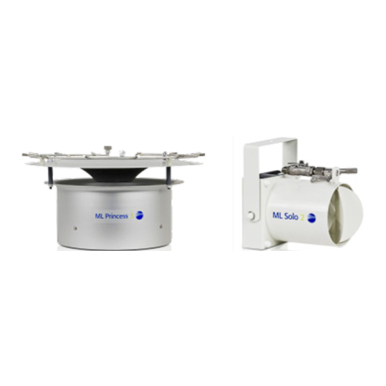
Figure 1: ML Princess direct room humidification system General description The Condair ML Princess direct room humidification head is a state-of-the-art high pressure adiabatic dispersion unit. It is part of a complete high pressure humidification system with one or more humidifica- tion units and one or more high pressure pump stations. -
Page 16: Assembly Overview
Electrical connection box placed under the fan and shown above. Recommended cables: 230 V Cable 3 x 0.75 PKAJ, Black 115 V ÖLFLEX Control TM 3G1 UL Figure 2: Electrical connection box 2591584-B_EN_1901 ML Systems ML Princess - Direct room humidification... -
Page 17: Nozzle Ring Installation
3. Make sure that the filter fixture is attached securely and the O-ring is in place before assembling the filter union. Close the ball valve when the unit is finally mounted. Ball valve Nozzle Nozzle ring Figure 3: Assembling Princess 2 2591584-B_EN_1901 ML Systems ML Princess - Direct room humidification... -
Page 18: Warning Label
Use a set of polygrip pliers to tighten the nozzle (approximately 1/8 turn) (torque: 1.5 ft.lb (2.1 Nm) (2.1 Nm)) • Ensure that the nozzle itself is tightened by tightening on the tip of the nozzle. 2591584-B_EN_1901 ML Systems ML Princess - Direct room humidification... -
Page 19: Installation Of Optional Air Filter
(woodworking, composite sanding, etc.) it may be necessary often to clean filters due to the high dust loads that are carried with the conveying air. 1. ML Princess seen from below without filter 2. Install the filter while the fan is in operation 3. -
Page 20: Placement Overview
Observe and comply with all local and national codes dealing with water and electrical installations. Condair Ltd. does not accept any liability for installation of humidification equipment by unqualified per- sonnel, or the use of equipment/parts that are not authorized by Condair. - Page 21 • Position the Condair ML Princess units in such a way to enable the atomized mist to spread freely. When the mist is prevented from spreading by obstacles (e.g. ceilings, beams, ventilation ducts, airflow, machinery, etc.), turbulences can build up and condensation may occur as a result.
-
Page 22: Hose Layout For Ml Princess
Solenoid 1/8" 1/8" 1/8" valve 1/4" 1/4" 1/8" 1/8" 1/4" 1/4" 1/4" 1/8" 1/8" 1/8" 1/8" 1/8" 1/4" WATER OUT HIGH PRESSURE WATER IN Drain hose Figure 8: Hose layout parallel 2591584-B_EN_1901 ML Systems ML Princess - Direct room humidification... -
Page 23: Placement Of Heads
5.3.2 Placement of heads Min. distance = 26 ft. (8.0 m) Figure 9: Distances between modules 2591584-B_EN_1901 ML Systems ML Princess - Direct room humidification... -
Page 24: Atomization Clearances
5.3.3 Atomization clearances Figure 10: Miscellaneous mounting distances 2591584-B_EN_1901 ML Systems ML Princess - Direct room humidification... -
Page 25: Mounting The Humidifier
5.4.1 Ceiling installation Adjust the chains so that the unit is level. After flushing and bleeding of ML Princess remove the excess chain and close S-hooks. The chains have to be fastened to the ceiling with appropriate material (screws, raw plugs, concrete screw anchors etc.). -
Page 26: Connecting Water And Power
Cable High pressure hose Figure 12: Connecting water and power to the ML Princess 2 The high pressure hose is connected to the ball valve. The hose can be strapped to the chain using cable ties. Avoid vertical U-turns on the hose. This might cause pockets of air in the hose. -
Page 27: Optional - Wall Mount
5.4.3 Optional - Wall mount The bracket is used for wall mounting of ML Princess 2, where only humidification out into the room is wanted. Together with the wall bracket, a shielding for the fan is supplied, so that the air does not blow against the wall. -
Page 28: Spare Parts
Nozzle ring without ball valve, filter and nozzles 102 200 001 Ball valve, complete 102 910 000 Bracket set for nozzle ring ML Princess 2 102 901 000 Fan for ML Princess 2, 230 VAC 310 010 000 Fan for ML Princess 2, 115 VAC 310 010 002 Bag with 8 nozzles, 3.3 lb/h (1.5 l/h) -
Page 29: Product Specifications
Product specifications 5.6.1 Technical data for ML Princess 2 Weight 20 lb (9.2 kg) Number of nozzles 8 nozzles Recommended nozzle size 5.5 lb/h or 10 lb/h (2.5 l/h or 4.5 l/h) Material Powder painted steel 37 Motor 75W, 900 RPM... -
Page 30: Technical Data For Nozzles
3.3 ft. (1.0 m) 6.6 ft. (2.0 m) 9.8 ft. (3.0 m) 16.4 ft. (5.0 m) As an option the fan speed is reduced. Sound power (LWA) at 50% voltage is 56.0 dB(A) 2591584-B_EN_1901 ML Systems ML Princess - Direct room humidification... -
Page 31: Declaration Of Compliance
Declaration of compliance 2591584-B_EN_1901 ML Systems ML Princess - Direct room humidification... -
Page 32: Ml Solo - Direct Room Humidification
Humidity is produced as water under high pressure (1015 psi (70 bar)) is atomized into micro-sized particles which are instantly absorbed into the surrounding air. The Solo units are typically attached to walls or columns via specific Condair Solo brackets, and water is fed via the high pressure tubing and electricity is fed via cables. -
Page 33: Assembly Overview
Assembly overview Figure 15: Assembling the ML Solo 2591584-B_EN_1901 ML Systems ML Solo - Direct room humidification... -
Page 34: Solo Assembly
6.2.1 Solo assembly WARNING! Never unscrew a nozzle on a pressurised unit. Disconnect power to the pump station when working on high-pressure system. CAUTION! Be careful! The threads on the nozzles break easily, the nozzle seals with an O-ring and hence does not need to be tightened very hard, just a little more than you can do by hand. -
Page 35: Mounting The Humidifier
The positioning of a system is always determined during planning and noted in the system documents. Prior to mounting the ML Princess unit, ensure that all hose layouts, distances between heads and at- omization clearances have been considered and adhered to, as per... - Page 36 Mounting bracket Metal washer Supporting strap Plastic washer ML Solo with wall mounting 2 mm (~ 5/64") Allen key ML Solo with ceiling mounting Figure 17: Mounting the ML Solo, wall or ceiling 2591584-B_EN_1901 ML Systems ML Solo - Direct room humidification...
- Page 37 Wall fixture Ceiling fixture 5.1" 8.7" (130 mm) (220 mm) 5.1" (130 mm) 2.8" (70 mm) 2.8" (70 mm) 8.9" (225 mm) Figure 18: Wall and ceiling fixtures 2591584-B_EN_1901 ML Systems ML Solo - Direct room humidification...
-
Page 38: Placement Overview
Placement overview 6.4.1 Hose layout for ML Solo 2591584-B_EN_1901 ML Systems ML Solo - Direct room humidification... -
Page 39: Atomization Clearances
6.4.2 Atomization clearances 2591584-B_EN_1901 ML Systems ML Solo - Direct room humidification... -
Page 40: Placement Of Heads
6.4.3 Placement of heads 2591584-B_EN_1901 ML Systems ML Solo - Direct room humidification... -
Page 41: Product Specifications
Product specifications 6.5.1 Technical data for ML Solo ML Solo 1 ML Solo 2 Weight 4.4 lb (2 kg) 4.4 lb (2 kg) Size (h x w x d) 7.1 x 5.9 x 6.7 inch 7.1 x 5.9 x 6.7 inch (180 x 150 x 170 mm) (180 x 150 x 170 mm) Noise level... -
Page 42: Nozzle Part And Size
6.5.3 Nozzle part and size Nozzle size Item number 3.3 lb/h (1.5 l/h) 103 200 001 5.5 lb/h (2.5 l/h) 103 160 000 6.5.4 Nozzle specifications Working pressure 507-1015 psi (35 - 70 bar) Material Stainless steel Anti-drip valve Standard 6.5.5 Accessories Colour Item number... -
Page 43: Declaration Of Compliance
Declaration of compliance CE - Declaration of Compliance Manufacturer: Condair A/S Technical Manager.: Jesper Lund -Jensen Parallelvej 2 8680 Ry We hereby declare, that the following spray modules for humidification purposes with ML pump systems: ML Solo 1; ML Solo 2... -
Page 44: Ml Flex - Direct Room Humidfication
Therefore ML Flex nozzles and tubing are placed in high ceiling areas. Condair ML Flex is suitable for humidification in industrial and horticultural industry, as well as for dust control in rooms with high dust load, such as the textile industry. - Page 45 The system is built with flexibility in mind, it can be easily designed or dimensioned to suit practically any project. ML Flex System allows you to choose between wall and ceiling mounting. The nozzles are mounted in the T-sections which can be rotated individually. Humidity is produced as water under high pressure (1015 psi (70 bar)) is atomized into micro-sized particles which are instantly absorbed into the surrounding air.
-
Page 46: Assembly Overview
Observe and comply with all local and national codes dealing with water and electrical installations. Condair does not accept any liability for installation of humidification equipment by unqualified personnel, or the use of equipment/parts that are not authorized by Condair. - Page 47 Mount the hose connection T-piece. Remember to place the O-ring. Join to flex tubes with T-pieces. Remember the O-rings. The nozzle fixture has to be on top of the assembly to avoid air pockets and to ensure the correct spray direction. The end piece is mounted on the last tube in line.
- Page 48 Connect the 1/8" high pressure hose to the hose nipple. Flush the system thoroughly before fitting the nozzles. Please observe that the nozzle pointing towards the wall is fitted with a blind nozzle. 2591584-B_EN_1901 ML Systems ML Flex - Direct room humidfication...
- Page 49 OPTIONAL BALL VALVE If a ball valve is needed this is fitted between high pressure hose coupling and the hose coupling on the flex system. Retighten by use of two fork wrenches NV17 (span of jaws). Ceiling suspension The system is hung up using the same fitting as for wall suspension and by means of either chains or wires.
-
Page 50: Inserting The Nozzle
7.2.2 Inserting the nozzle WARNING! Never unscrew a nozzle on a pressurised unit. Disconnect power to the pump station when working on high-pressure system. CAUTION! Be careful! The threads on the nozzles break easily, the nozzle seals with an O-ring and hence does not need to be tightened very hard, just a little more than you can do by hand. -
Page 51: Water Connection
7.2.3 Water connection High pressure hose Figure 24: Connecting water to ML FLEX The high pressure hose is connected to the ball valve. The hose can be strapped to the chain using cable ties. Avoid vertical U-turns on the hose. This might cause pockets of air in the hose. 7.2.4 Completed assembly Wall fixture... - Page 52 Stainless steel wire Stainless steel chain Ceiling fixture Figure 26: Ceiling mounted ML FLEX 2591584-B_EN_1901 ML Systems ML Flex - Direct room humidfication...
-
Page 53: Placement Overview
• Position the Condair ML Flex atomizers in such a way to enable the atomized mist to spread freely. When the mist is prevented from spreading by obstacles (e.g. ceilings, beams, ventilation ducts, airflow, machinery, etc.), turbulences can build up and condensation may occur as a result. -
Page 54: Positioning Clearances
7.3.1 Positioning clearances Building element, ventilation lighting or similar 20 feet (6 m) 10 feet (3 m) Figure 27: Distances between modules 2591584-B_EN_1901 ML Systems ML Flex - Direct room humidfication... -
Page 55: Parts And Spare Parts
Parts and spare parts Some of the following parts and spare parts may only be available in select markets. Contact your local sales representative for more information on pricing and lead times. Item Part No. Standard tubes 9.8 inches (0.25 m) 120 304 007 1.6 ft. - Page 56 Item Part No. End piece with 120 330 007 double nozzles Wall fixture 120 318 000 Ceiling fixture 120 319 000 Fixture for 3/8" tubes 730 020 280 Used when mounting on a support pipe Stainless nozzles 5.5 lb/h (2.5 l/h) 201 020 003 10 lb/h (4.5 l/h) 201 020 001...
-
Page 57: Product Specifications
Item Part No. Small ball valve 25 78 176 Chain 20 ft. (6 m) 101 101 000 33 ft. (10 m) 101 100 000 328 ft. (100 m) 101 104 000 Product specifications 7.5.1 Technical data for ML Flex Wall / ceiling fixture ≈... -
Page 58: Ml Uno - Direct Room Humidification
ML UNO - Direct room humidification Figure 28: ML Uno direct room humidification system 2591584-B_EN_1901 ML Systems ML UNO - Direct room humidification... -
Page 59: General Description
General description ML Uno is the smallest unit from Condair Humiditiy Ltd. The size of the unit is that of a small spot lamp. It is well suited for low-ceilinged rooms, even where a high replacement of air is required, and is because of its invisibility well suited for any purpose. -
Page 60: Mounting Brackets
Mounting brackets Bracket for a single Uno Figure 30: Bracket for mounting on wall Figure 31: Bracket for mounting on ceiling Bracket for two Unos Figure 32: Bracket for mounting on wall Figure 33: Bracket for mounting on ceiling (Min. distance to wall 200 mm) 2591584-B_EN_1901 ML Systems ML UNO - Direct room humidification... -
Page 61: Solenoid Valve (Zone Valve)
Solenoid valve (zone valve) General Description If the system consists of several different zones, load permitting, one pump is sufficient to supply all the zones. Each zone must be equipped with a solenoid valve set, which opens when the zone needs humidification and relieves the pressure in the high-pressure hose when the zone stops. -
Page 62: Solenoid Valve Sets
Solenoid valve sets 9.2.1 Solenoid valve set 0 - 20.0 gph (0 - 76 l/h) Data source: TD025GB 106.207.005 106.208.005 Brown Blue N (L2) Yellow/Green Inlet Outlet Ball 60µ valve filter 1/4" RG Drain 1/4" RG 10/8 mm Drain hose Spare parts 102.400.000 Filter for pre-filter at nozzle ring,... -
Page 63: Solenoid Valve Set 16.0 - 95.0 Gph (60 - 360 L/H)
9.2.2 Solenoid valve set 16.0 - 95.0 gph (60 - 360 l/h) 106.210.00 106.211.00 Inlet Outlet Ball 60µ valve filter 10/8 mm Drain hose 1/4" RG Drain 1/4" RG Spare parts 106.500.000 Filter for pre-filter at solenoid valve set, length: 0.98 inch, 60 μ nominal 106.531.000 Coil, 240 VAC, 50 Hz 106.532.000... -
Page 64: Solenoid Valve Set 31.7 - 475.5 Gph (120 - 1800 L/H)
9.2.3 Solenoid valve set 31.7 - 475.5 gph (120 - 1800 l/h) 106.215.00 106.220.00 106.216.00 106.221.00 Inlet Outlet Ball 60µ 1/4" RG valve filter 3/8" RG 1/4" RG 3/8" RG 1/4" RG Drain 1/4" RG Spare parts 106.500.000 Filter for pre-filter at solenoid valve, length: 0.98 inch, 60 μ... -
Page 65: Choosing Size And Type
Choosing size and type The maximum flow of the department determines type and combination. Softened water allows for the use of brass valves, while water from reverse osmosis (RO) requires the use of corrosion-proof valves. Surface water with a conductivity less than 50 μS/cm requires the use of corrosion-proof valves. Pressure release hoses Important: Discharge hoses from pressure release valves must be conducted to a free outlet. -
Page 66: Ml Nozzles
ML nozzles 10.1 ML standard nozzles Data source: TD122GB - 03 Description: The ML standard nozzles are specifically designed nozzles of highest quality, which atomizes water under high pressure to millions of microscopic particles sized 5-10 microns, which immediately evaporate in to the surrounding air. - Page 67 Specifications: Nozzle 5.5 lb/h (2.5 l/h) 10 lb/h (4.5 l/h) 13.2 lb/h (6.0 l/h) Capacity 3.7 – 5.5 lb/h 7.7 - 11.0 lb/h 12.5 - 13.2 lb/h (1.7 - 2.5 l/h) (3.5 - 4.5 l/h) (5.7- 6.0 l/h) Working pressure 507 - 1015 psi 507 - 1015 psi 507 - 1015 psi...
-
Page 68: Ml Low Capacity Nozzles
10.2 ML low capacity nozzles Data source: TD116GB - 01 Unique high-technology nozzle from Condair • Extremely fine atomization • Minimum humidification power • Optimum cooling and humidification effect Description: The nozzle atomizes water under high pressure into millions of microscopic particles in sizes from 5-15 micron, which immediately evaporates into the ambient air. - Page 69 Specifications: Nozzle 3.3 lb/h (1.5 l/h) Capacity 2.6 - 3.3 lb/h (1.2 - 1.5 l/h) Working pressure 507-1015 psi (35 - 70 bar) Material Stainless steel Thread 12/24 UNC/2A Anti-drip valve Standard Filter Standard Requirements for conductivity μS/cm 5 < EC < 80 Part number Part number 103.200.001 Spare parts:...
-
Page 70: A Appendix
Appendix Mounting instructions Data source: MA048GB - 01 Figure 36: Mounting instruction 2591584-B_EN_1901 ML Systems Appendix-A... - Page 71 Data source: MA063GB - 00 Figure 37: Mounting instruction 2591584-B_EN_1901 ML Systems Appendix-A...
-
Page 72: Stainless Steel Screw Couplings
Allen key. 6) Do not allow the hose to turn around while the insert is being screwed in - use special tool from Condair and screw in the insert in one long movement. - Page 73 Coupling size 1/16" 13/64 ± 1/64 inch 1/16 ± 1/64 inch Min. 1 3/8 inch 1/32 inch 13/64 inch 31/64 inch (5.0 mm ±0.2 mm) (1.6 mm ±0.2 mm) (Min. 35 mm) (0.8 mm) (5.0 mm) (12.5 mm) 1/8" 9/32 ± 1/64 inch 9/64 ±...
-
Page 74: High Pressure Hose Dimensioning
High pressure hose dimensioning Data source: TI013GB - 01 Minimum Maximum Maximum Minimum bending Hose dimension flow flow lenght radius (@ 90°) 0.26 gph 5.3 gph 82 ft. 3.2 inch 1/16" (1 l/h) (20 l/h) (25 m) (80 mm) 2.6 gph 23.8 gph 196 ft. -
Page 75: Installation Examples
Installation examples 2591584-B_EN_1901 ML Systems Appendix-A... - Page 76 2591584-B_EN_1901 ML Systems Appendix-A...
- Page 77 2591584-B_EN_1901 ML Systems Appendix-A...
- Page 78 2591584-B_EN_1901 ML Systems Appendix-A...
-
Page 79: B Appendix
Appendix Humidity sensors Data source: TD150GB-03 B.1.1 HST2-010 HST2-010, item no. 105 501 000 The HST2-010 is an electric sensor for measurement of the relative humidity and temperature in atmos- pheric air. The relative humidity is transformed to a 0-10.0 VDC signal corresponding to 0-100 % RH. Furthermore the HST2-010 has a built in PT1000 temperature sensor element. - Page 80 HST2-10 HST2-420 HST2-10 HST2-420 General specifications Measuring range 0 – 90 % RH Tolerance at 77 °F ±4.5 % RH @ 30 – 80 % RH +/-7 % RH @ 0 to 30 % RH & 80 to 100 % RH Tolerance, +/-5 % RH @ 30 to 80 % RH full temperature range...
-
Page 81: Dol114
B.1.3 DOL114 DOL114, item no. 105 525 000 Product description DOL 114 is a high-precision sensor for measuring relative humidity and temperature. It is intended for application in livestock houses but is also well suited for a number of industrial applications. Figure 47: DOL 114 Important maintenance Clean DOL114 using water and a brush. - Page 82 After the sensor has been exposed to water and condensation, the sensor requires time during which the relative humidity is less than 80% in order to measure correctly. Do not bend the sensor as this would inflict permanent damage on the electronics of the sensor. Dol-sensors reserve the right to change this document and the product herein described without further notice.
- Page 83 °C (black) % RH (white) V+ (brown) Supply voltage 11 - 30 VDC GND (blue) Figure 51: Connection Table 1: Signals and wire colors in other products DOL 14 DOL 14 HQ DOL 114 Black = +13-24 VDC White = +13-28 VDC Brown = +11-30 VDC Brown = 0…10 V / %RH Green = 0…10 V / %RH...
- Page 84 Humidity Temperature Measuring range 0-100 %RH -40 °F – 140 °F (-40 °C – +60 °C) Accuracy 1 ±2 % RH (40-85 %) ±3 % RH (10-95 %) +50 – 104 °F (40 °C) ±0.9 °F at 21 – 104 °F (40 °C) * at -22 –...
-
Page 85: Nozzle Swivel Adapter (Optional)
Nozzle swivel adapter (Optional) Using this adapter it is possible to rotate the nozzle in a direction to avoid spraying on other items. Female thread: 12/24 UNC/2B Male thread: 12/24 UNC/2A Swing angle: 50° Angle of rotation: 360° 50° 360° 2 adapters 1 adapter Material: AISI 303... - Page 86 Notes...
- Page 87 Warranty Condair Inc. and/or Condair Ltd. (hereinafter collectively referred to as THE COMPANY), warrant for a period of two years after installation or 30 months from manufacturer’s ship date, whichever date is earlier, that THE COMPANY’s manufactured and assembled products, not otherwise expressly warranted, are free from defects in material and workmanship.
- Page 88 CONSULTING, SALES AND SERVICE: U.S.A. 826 Proctor Avenue Ogdensburg, NY 13669 CANADA 2740 Fenton Road Ottawa, Ontario K1T 3T7 TEL: 613.822.0335 / 1.866.667.8321 FAX: 613.822.7964 EMAIL: na.info@condair.com WEBSITE: www.condair.com...
Need help?
Do you have a question about the ML Princess and is the answer not in the manual?
Questions and answers