Table of Contents
Advertisement
Quick Links
Advertisement
Table of Contents
Troubleshooting

Subscribe to Our Youtube Channel
Related Manuals for dymax BlueWave 200 Version 3.1


Summary of Contents for dymax BlueWave 200 Version 3.1
- Page 1 BlueWave 200 Version 3.1 ® UV Light-Curing Spot Lamp User Guide...
- Page 2 Any warranty applicable to the product, its application, and use is strictly limited to that contained in the Dymax standard Conditions of Sale. Dymax recommends that any intended application be evaluated and tested by the user to ensure that desired performance criteria are satisfied.
-
Page 3: Table Of Contents
Where to Get Help ..................4 Safety ..................4 General Safety Considerations ............... 4 Specific Safety Considerations ............... 5 Dymax UV Light-Curing System Safety Considerations ..... 5 Product Overview ..............7 Unpacking the BlueWave 200 ..........8 Unpacking and Inspecting Your Shipment..........8 Parts List .................... - Page 4 Solving Problems ..............30 Troubleshooting ..................30 Frequently Asked Questions ..............31 Diagnostic Display .................. 32 Spare Parts and Accessories ..........33 Spare/Replacement Parts ..............33 Options/Accessories ................33 Specifications ..............34 Declaration of Conformity ..........35 Definition of Terms ............. 36 Warranty ................
-
Page 5: Introduction
To use this system safely, it must be set up and operated in accordance with the instructions given by Dymax. Using the system in any other manner will impair the protection of the system. Dymax assumes no liability for any changes that may impair the protection of the system. -
Page 6: Specific Safety Considerations
UV Exposure Standard Dymax UV light-curing systems and bulbs have been designed to primarily emit UVA light (Figure 1). UVA light is generally considered the safest of the three UV ranges: UVA, UVB, and UVC. Although OSHA does not currently regulate ultraviolet light exposure in the workplace, the American Conference of Governmental Industrial Hygienists (ACGIH) does recommend Threshold Limit Values (TLVs) for ultraviolet light. - Page 7 Ozone Standard Dymax bulbs (UVA type) generate an insignificant amount of UVC and therefore essentially no ozone. Some UV light-curing systems, like those used to cure UV inks, emit primarily “shortwave” (UVB and UVC) energy. Upon exposure to UVC light (specifically <240 nm), oxygen molecules (O...
-
Page 8: Product Overview
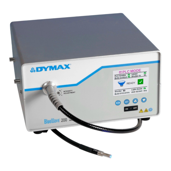
Product Overview The BlueWave 200 is a high-intensity, UV light-curing spot lamp system used for small-area curing of adhesives, coatings, and potting materials. It emits up to an 8-mm diameter spot of UV light from a liquid lightguide (sold separately). The lightguide can be hand-held for complete mobility or clamped into position on assembly equipment or workstations for repetitive operations. -
Page 9: Unpacking The Bluewave 200
Contact Dymax so that new parts can be shipped to you immediately. Check that the parts included in your order match those listed below. If parts are missing, contact your local Dymax representative or Dymax Customer Support to resolve the problem. -
Page 10: Setting Up The Bluewave 200
2,000-hour bulb replacement. If you need additional assistance in evaluating the environment or in setting-up your equipment, contact Dymax Applications Engineering. Connect the Power Cord to the Power Receptacle on the rear of the BlueWave 200. Plug the Power Cord into a grounded wall outlet. - Page 11 Remove the Protective End Caps from the Lightguide. Visually inspect the two ends of the Lightguide to verify that no foreign material is present. The ends of a Dymax liquid-filled Lightguide can be cleaned with isopropyl alcohol as required to remove foreign material and deposition from outgassing.
-
Page 12: Becoming Familiar With The Controls
Becoming Familiar with the Controls There are 6 simple controls which can adjust all features of the BlueWave 200 (Figure 8). Figure 8. Front Panel Controls LCD Display Set Button Up & Down Arrows Run Button Bulb Off Button Bulb On Button LCD Display –... - Page 13 There are simple displays which will give the following status of the BlueWave 200 ( Figure 9). Figure 9. Front Panel Status (Displayed Status is Mode Dependent) Operational Mode PLC Enable (Input) PLC Enabled. PLC Disabled. Bulb ON Control (Input) Bulb ON Enabled.
-
Page 14: Turning The Bluewave 200 On
Turning the BlueWave 200 On Turn on the power by moving the On/Off Switch on the back panel to the on position (Figure 10). The LCD Display will turn on and show the product configuration screen (Figure 11). NOTE: If you have already set the BlueWave 200 up for PLC operation according to the instructions in “Operating in PLC Mode”... -
Page 15: Setting An Operating Mode
Figure 12. Bulb Ignition & Warm-Up Screens Bulb Ignition Screen Bulb Warm-Up Screen Setting an Operating Mode Introduction to Operating Modes Your BlueWave 200 has three basic operating modes: Manual Mode, Timed Mode, and PLC Mode. Manual Mode: The shutter opens whenever the foot pedal or the run button on the front panel is pressed. When the shutter is open, the timer counts up from zero and UV light passes through the lightguide. -
Page 16: Choosing An Operating Mode
Choosing an Operating Mode NOTE: Upon power-up, your BlueWave 200 will default to its last configuration settings. Follow the instructions in “Turning BlueWave On” (Page 13). The BlueWave 200 will power up in Manual, Timer, or PLC Mode (Figure 13). NOTE: If the BlueWave 200 powers up in PLC Mode, you cannot change modes from the front panel controls. - Page 17 Press and release the Button. The screen should look like Figure 18. NOTE: If the PLC Switch was not set correctly, the screen in Figure 19 will appear. Turn off the BlueWave and refer to “Using the PLC Switch” (Page 22) for instructions on how to set the PLC Dip Switch. Figure 17.
-
Page 18: Operating In Manual Mode
NOTE: If you do not see “PLC MODE” on the screen, then you did not hold the button down for a long time. Use Arrows to select “CANCEL” and press the Button. No changes are made and you can try again. Use the Arrows to select “PLC MODE”. -
Page 19: Operating In Timed Mode
NOTE: If the BlueWave 200 is not in Manual Mode, follow the instructions in “Choosing an Operating Mode” (Page 15). Position the Lightguide end no closer than 0.25" [0.64 cm] from the material being cured. Positioning the Lightguide End too close can cause the Lightguide End to become cloudy from vapors coming off the curing material. This cloudiness can reduce UV output by as much as 50%. -
Page 20: Procedure To Adjust Timer
Procedure to Adjust Timer CAUTION! Always wear protective goggles or a face shield when working near UV light. Never look directly at the light exiting the lightguide. Ensure the BlueWave 200 is in Timed Mode. (Figure 28) NOTE: If the BlueWave 200 is not in Timed Mode, follow the instructions in “Choosing an Operating Mode” (Page 15). If the time on the screen is correct, skip to Step 8. -
Page 21: Operating In Plc Mode
Operating in PLC Mode PLC Mode Description CAUTION! Always wear protective goggles or a face shield when working near UV light. Never look directly at the light exiting the lightguide. The PLC is capable of opening the shutter at any time, including when the bulb becomes ready in PLC mode or when a user selects PLC Mode from the front panel controls. - Page 22 Figure 33. Removal of the Covers (Far Side) Loosen Screws (Do Not Remove) Remove Screws U S E R G U I D E B L U E W A V E ® 2 0 0 V 3 . 1...
- Page 23 Figure 34. PLC Dip Switch Location Adjust the PLC Switch (see below) and replace the Inner and Outer Covers. Adjusting the PLC Switch When Switch 2 is moved towards the back panel, PLC Mode is enabled. PLC Mode can be activated from front panel key presses.
-
Page 24: Wiring The Plc Interface
Wiring the PLC Interface The following information will allow you to connect any PLC to the BlueWave 200. Input Signal Definition NOTE: Asserting an input signal means connecting the input pin to +24VDC return. Approximately 12 mA will flow out of the pin. - Page 25 Output Signal Definition NOTE: Output signals which are asserted can sink up to 2.5 mA with 5 VDC maximum between signal output pin and +24 VDC return. The current flows out of the +24 VDC return pin. A sample wiring diagram is given in Figure 36 (Page 25). Each Output signal which is not asserted may draw up to 5 μA of current.
- Page 26 Sample Wiring Diagram Figure 36. Sample Wiring Diagram +24VDC USE ONLY THE 2000 Ω SIGNALS REQUIRED BY THE PLC PROGRAM FROM PLC 24VDC POWER SUPPLY 10000 Ω TO PLC +24VDC RETURN Connector Pin Out The PLC Connector pin numbers are shown in Figure 37 below. Figure 37.
-
Page 27: Plc Front Panel Emergency Stop
PLC Front Panel Emergency Stop Figure 38. PLC Emergency Stop Function Press the Off Button on the Front Panel to close the Shutter and turn off the Bulb to immediately override any commands issued by the PLC. Press the On Button or cycle power to re-enter PLC Mode. -
Page 28: Setting The Intensity
Setting Up the Curing Process Methods Prior to production, Dymax advises customers to conduct testing to determine the time and intensity required to fully cure their resin in their specific application. Typically, users validate by one of the following methods: •... -
Page 29: Maintaining The Bluewave 200
Maintaining the BlueWave 200 The BlueWave 200 was designed to operate with minimum maintenance. Typically, the Bulb must be replaced after it has operated for 2,000 hours. Bulb Replacement Warning As the Bulb nears the end of its 2,000-hour life, the LCD Display will yellow highlight the Bulb Hours. The 1,950 Hour Warning output on the PLC connector also becomes asserted. -
Page 30: Lightguide
200 and remove the Fuse Holder with a small screwdriver. Remove the Fuses from the Fuse Holder and install new Fuses. Replace the Fuse Holder into the Power Receptacle. The correct Fuses are Dymax PN 41099, 4.0 Amp fast-acting type. -
Page 31: System Cleaning
Transmission loss in Compare the lightguide output Replace the Lightguide. Lightguide too great against a new lightguide (or use Output the Dymax lightguide simulator) to Intensity determine transmission loss. Contaminants on Visually examine ends of Clean with Lightguide Ends with Lightguide Lightguide for contaminants. -
Page 32: Frequently Asked Questions
Frequently Asked Questions or severe bends in the length of the Lightguide. A leaking Lightguide will drastically reduce intensity Q. My BlueWave 200 will not turn on. transfer. Lightguides should be seated properly within the Lightguide mount and never be bent more •... -
Page 33: Diagnostic Display
Incorrect alignment of the Shutter to the Bulb Mount Assembly. The LCD Screen will display any faults detected by the If the problem still exists please contact Dymax BlueWave 200 (Figure 49). Contact Dymax for Customer Support assistance, since most faults can be resolved over the phone. -
Page 34: Spare Parts And Accessories
Fiber Optic 4-Pole Lightguide, 3 mm x 1 Meter 39791 5 mm Lightguide End Protector (12% Energy Loss) 40539 Miscellaneous Dymax ACCU-CAL™ 50 Radiometer (Spot Model) 39560 BlueWave Case with Foam 38679 U S E R G U I D E B L U E W A V E ®... -
Page 35: Specifications
Specifications Property Specification 41015 North American Version (with 115V standard plug) Part Numbers 41014 Asian Version (with type G plug) 41013 BlueWave 200 with no power cord* Intensities Total (280-450) 40+ W/cm Visible (400-450 nm) 17+ W/cm UVA** (320-395 nm) 17+ W/cm (280-320 nm) 7 W/cm... -
Page 36: Declaration Of Conformity
Declaration of Conformity U S E R G U I D E B L U E W A V E ® 2 0 0 3 . 1... -
Page 37: Definition Of Terms
Ultraviolet (UV) - The invisible region of the spectrum just beyond the violet end of the visible region. Wavelength ranges in general from 1.0 to 400 nm. Dymax bulbs (burners) do not radiate energy in deep ultraviolet; there are very minute amounts below 220 nm and practically nothing can be sensed below 200 nm. -
Page 38: Warranty
Warranty From date of purchase, Dymax Corporation offers a one-year warranty against defects in material and workmanship on all system components with proof of purchase and purchase date. Unauthorized repair, modification, or improper use of equipment may void your warranty benefits. The use of aftermarket replacement parts not supplied or approved by Dymax Corporation, will void any effective warranties and may result in damage to the equipment. - Page 39 Index Bulb Replacement Procedure, 29 PLC Mode, 21 Bulb Replacement Warning, 29 Front Panel Emergency Stop, 27 Contact Information, 5 Wiring the PLC Interface, 24 Controls, 12 Safety, 5 Curing System Safety, 6 Safety of UV Light Bright, Visible Light, 7 Definition of Terms, 37 High-Temperature Surfaces, 7 Help, 5...
- Page 40 Dymax Corporation, U.S.A. The data contained in this bulletin is of a general nature and is based on laboratory test conditions. Dymax Europe GmbH does not warrant the data contained in this bulletin. Any warranty applicable to products, its application and use is strictly limited to that contained in Dymax Europe GmbH’s General Terms and Conditions of Sale published on our website.
Need help?
Do you have a question about the BlueWave 200 Version 3.1 and is the answer not in the manual?
Questions and answers