
Subscribe to Our Youtube Channel
Related Manuals for dymax BlueWave VisiCure


Summary of Contents for dymax BlueWave VisiCure
- Page 1 BlueWave LED Flood System User Guide ® Large-Area LED Light Source Instructions for Safe Use ■ ■ Setup and Operation ■ Maintenance ■ Ordering Spare Parts and Accessories...
- Page 2 System designs enable stand-alone configuration or integration into your existing assembly line. Please note that most dispensing and curing system applications are unique. Dymax does not warrant the fitness of the product for the intended application. Any warranty applicable to the product, its application, and use is strictly limited to that contained in the Dymax standard Conditions of Sale.
-
Page 3: Table Of Contents
Dymax BlueWave® LED Flood System User Guide Contents Introduction ..............................5 Introduction to the User Guide ............................5 Where to Get Help ................................5 Safety / Sécurité ............................. 5 General Safety Considerations ............................6 Specific Safety Considerations ............................6 Safety Symbol Index ................................ 7 Dymax Light-Curing System Safety Considerations ...................... - Page 4 Dymax BlueWave® LED Flood System User Guide Cleaning the Quartz Optic Plate ............................ 25 Troubleshooting ............................25 Spare Parts and Accessories .......................... 28 Spare/Replacement Parts .............................. 28 Options/Accessories ..............................28 Specifications ..............................29 Specifications................................. 29 Index ................................31...
-
Page 5: Introduction
Final installation must not block vents. To use a BlueWave LED Flood System safely, it must be set up and operated in accordance with the instructions given by Dymax. Using the flood system in any other manner will impair the protection of the system. Dymax assumes no... -
Page 6: General Safety Considerations
Dymax n'est pas responsable des changements pouvant diminuer la protection du système de séchage. General Safety Considerations All users of Dymax equipment should read and understand this user guide before assembling and using the equipment. To learn about the safe handling and use of light-curable formulations, obtain and read the MSDS for each product. -
Page 7: Safety Symbol Index
Dymax BlueWave® LED Flood System User Guide WARNINGS! Looking directly at the high-intensity light emitted by the BlueWave Large Area LED Array can result in eye injury. To prevent eye injury, never look directly at the high-intensity light and always wear protective goggles (provided). - Page 8 Flexible Film – Translucent light-blocking, flexible urethane films can be used to quickly create workstation shielding. This light-blocking, flexible urethane film is available from Dymax. Call for assistance. High-Temperature Surfaces Surfaces exposed to high-intensity curing lights may rise in temperature. The intensity, distance, exposure time, cooling fans, and composition of the surface can all affect the rise in surface temperature.
-
Page 9: Product Overview
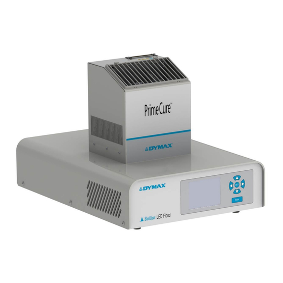
The BlueWave LED Flood System consists of two main components: an LED flood array and a power supply that contains the user interface. Dymax offers three different wavelength LED flood arrays: VisiCure® (405 nm), PrimeCure™ (385 nm), and RediCure™ (365 nm). Only one LED flood array can be connected to the power supply at a time via the interconnect cable. -
Page 10: Special Features And Benefits Of The Bluewave Led Flood System
Dymax BlueWave® LED Flood System User Guide Special Features and Benefits of the BlueWave LED Flood System The Dymax BlueWave LED Flood System is engineered for precise performance and long service life. Key features include: Feature Benefit Curing area up to 5" x 5" [12.7 cm x 12.7 cm]... -
Page 11: Back Panel
Dymax BlueWave® LED Flood System User Guide Back Panel The back panel includes these components and connection points: Power Cord Receptacle ■ — Connection point for the power cord. I/O (On/Off) Switch ■ — Moving the switch to the I (on) position powers up the power supply. Moving the switch to the O (off) position cuts power to the power supply. -
Page 12: Operation Modes
Final installation must not block vents. To use a BlueWave LED Flood System safely, it must be set up and operated in accordance with the instructions given by Dymax. Using the flood system in any other manner will impair the protection of the system. Dymax assumes no liability for any changes that may impair the protection of the curing system. -
Page 13: Unpacking And Inspecting Your Shipment
Open each box and check for equipment damage. If parts are damaged, notify the shipper and submit a claim for the damaged parts. Contact Dymax so that new parts can be shipped to you immediately. Check that the parts included in your order match those listed below. If parts are missing, contact your local Dymax representative or Dymax Customer Support to resolve the problem. -
Page 14: System Connections
Dymax BlueWave® LED Flood System User Guide System Connections WARNING! Make sure the unit is turned off and unplugged before you make any connections to the back panel. Never attempt to unplug or attach a cable when the unit is turned on. -
Page 15: Operating Modes
Dymax BlueWave® LED Flood System User Guide NOTE: If you enter intensity that is too low for the LED Flood Array attached the unit, the unit will beep for 5 seconds, and the intensity will not change. If you are operating in PLC mode, a PLC input signal allows intensity to be selected from this menu or allows intensity to be controlled directly by the PLC. -
Page 16: Choosing An Operating Mode
Dymax BlueWave® LED Flood System User Guide Choosing an Operating Mode NOTE: Upon power-up, your BlueWave LED Flood System will default to its last configuration settings. Figure 9. Mode Start-up Screens (Left to Right: Manual Mode, Timer Mode, PLC Mode) NOTE: If the BlueWave LED Flood System powers up in PLC Mode, you cannot change any settings via the front panel controls until you press the PLC Access Switch on the back panel. - Page 17 Dymax BlueWave® LED Flood System User Guide Selecting the PLC Mode from the Timer or Manual Mode: 1. Press the PLC Access Switch on the back of the unit (Figure 12). 2. From the main page, press the button to open the Options Menu (Figure 13) within 30 seconds.
- Page 18 Dymax BlueWave® LED Flood System User Guide Selecting Timer or Manual Modes from the PLC Mode: 1. Press the PLC Access Switch on the back of the unit (Figure 16). NOTE: The padlock will disappear from the PLC Mode screen after you press the PLC Access Switch.
-
Page 19: Operating In Manual Mode
Dymax BlueWave® LED Flood System User Guide Operating in Manual Mode Manual Mode Description Manual Mode means that the LED activates whenever the foot switch or the run button on the front panel is pressed. The LED remains active only as long as the foot switch or run button is pressed. When the foot pedal and run button are released, the LED shuts off. -
Page 20: Operating In Plc Mode
Dymax BlueWave® LED Flood System User Guide 3. Press and release the Button to enter the Options Menu (Figure 21). 4. Use Arrows so that “ADJUST TIMER” is flashing and press the Button. 5. The Adjust Timer Screen (Figure 22) will display. Use the Directional Keys to adjust the Timer to the correct value. -
Page 21: Wiring The Plc Interface
Dymax BlueWave® LED Flood System User Guide Wiring the PLC Interface Figure 23. 25-Pin D- Subminiature Connector The BlueWave LED Flood System includes a 25-pin D-subminiature connector (Figure 23) on the rear panel of the power supply for communication with a PLC or similar process control equipment. The connector provides for input and output signals. - Page 22 Dymax BlueWave® LED Flood System User Guide Input Signal Definition Note: Asserting an input signal means connecting the input pin to return. Approximately 3mA will flow out of the pin. The current is supplied from the +24VDC Supply. Un-asserting an input signal means that less than 1 microampere of current is drawn from the pin.
-
Page 23: Output Signal Definition
Dymax BlueWave® LED Flood System User Guide Output Signal Definition NOTE: Output signals which are asserted can sink up to 2.5 milliamperes with 5V maximum between signal output pin and +24VDC Return/Signal Common. The current flows through the output signal pin to the +24VDC Return/Signal Common pin. -
Page 24: Troubleshooting The Plc Interface
Dymax BlueWave® LED Flood System User Guide Troubleshooting the PLC Interface In PLC Mode, the LCD screen gives the status of all inputs to the Flood Unit. NOTE: The LCD screen also indicates the set point intensity emitted by the LED Head, which may be different from the intensity commanded by the PLC if the Intensity Control Method is via the front panel keyboard. -
Page 25: Cleaning The Quartz Optic Plate
Dymax BlueWave® LED Flood System User Guide Cleaning the Quartz Optic Plate Based on the cleanliness of your operating environment, establish a schedule for cleaning the LED array optic plate. When cleaning is required, shut the unit down and allow it to cool. Then clean the quartz optic plate surface (Figure 28) with a clean lint-free cloth and isopropyl alcohol. -
Page 26: Troubleshooting
Cable Problem Power down and restart the controller to reset. If the problem persists, note the number following the “E” and contact Dymax for further assistance There was a failure with the controller board. Power down and restart the Controller Board controller to reset. - Page 27 Power Supply. cm] of clearance is provided around the Cooling Fan Inlets. Unit appears to run hot Ensure that the Fan is operating. Contact Dymax The Fan is not operating. Application Engineering. The Power Supply is contaminated with dust or Contact Dymax Application Engineering.
-
Page 28: Spare Parts And Accessories
Dymax BlueWave® LED Flood System User Guide Spare Parts and Accessories Spare/Replacement Parts Item Part Number Key System Components LED Flood Power supply 41276 PrimeCure™ LED Flood Array – 385 nm Wavelength 41210 VisiCure® LED Flood Array – 405 nm Wavelength 41211 RediCure™... -
Page 29: Specifications
Dymax BlueWave® LED Flood System User Guide Specifications Specifications Property Specification 41260 Power cord NOT included* VisiCure® 41288 North American power cord with 120V plug 405 nm 41291 Asian Power cord 41261 Power cord NOT included* PrimeCure™ Part Numbers 41287... - Page 30 Dymax BlueWave® LED Flood System User Guide Figure 30. BlueWave LED Flood with PrimeCure™ Array– 385 nm Spectral Output Figure 31. BlueWave LED Flood with VisiCure® Array – 405 nm Spectral Output Figure 32. BlueWave LED Flood with RediCure™ Array – 365 nm Spectral Output...
-
Page 31: Index
Unauthorized repair, modification, or improper use of equipment may void your warranty benefits. The use of aftermarket replacement parts not supplied or approved by Dymax Corporation, will void any effective warranties and may result in damage to the equipment. - Page 32 Please note that most dispensing and curing system applications are unique. Dymax does not warrant the fitness of the product for the intended application.
Need help?
Do you have a question about the BlueWave VisiCure and is the answer not in the manual?
Questions and answers