Table of Contents
Advertisement
Available languages
Available languages
Quick Links
Bedienungsanleitung
celexon elektrischer Laser TV
Auszug
Vielen Dank für den Kauf dieses Produkts.
Für eine optimale Leistung und Sicherheit lesen Sie diese Anweisungen bitte sorgfältig
durch, bevor Sie dieses Produkt anschließen oder betreiben. Bitte bewahren Sie diese
Anleitung für eine spätere Verwendung auf.
Version: 32424_062
Advertisement
Table of Contents

Related Manuals for Celexon 1000029986


Summary of Contents for Celexon 1000029986
- Page 1 Bedienungsanleitung celexon elektrischer Laser TV Auszug Vielen Dank für den Kauf dieses Produkts. Für eine optimale Leistung und Sicherheit lesen Sie diese Anweisungen bitte sorgfältig durch, bevor Sie dieses Produkt anschließen oder betreiben. Bitte bewahren Sie diese Anleitung für eine spätere Verwendung auf.
- Page 2 Beschädigungen am Produkt zu finden sind. Sollten Sie äußerliche Beschädigungen an dem Gerät oder unerwartete oder unübliche Funktionsweisen feststellen, darf das Produkt nicht weiter genutzt werden. Kontaktieren Sie umgehend den Händler, bei dem Sie das Produkt gekauft haben oder celexon direkt (Web: www.celexon.de, Mail: info@celexon.de) für weitere Informationen. •...
- Page 3 Ihren Händler oder celexon direkt (Web: www.celexon.de, Mail: info@celexon.de). • Technische Änderungen und Irrtümer vorbehalten. Der Hersteller übernimmt keine Verantwortung für Sachschäden oder Personenschäden, wenn der Auszug außerhalb der empfohlenen Spezifikationen verwendet wird, oder bei unsachgemäßer Installation. HAFTUNGSAUSSCHLUSS Die Angaben in diesem Dokument können ohne vorherige Ankündigung durch den Hersteller geändert werden.
-
Page 4: Technische Daten
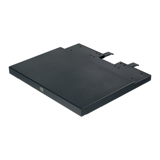
LIEFERUMFANG 1x Funk-Fernbedienung 1x Stromkabel 8x M5x35 Wandschrauben 8x M4x6 Kombischrauben 4x Moosgummi Klebepads 1x Triggerkabel 1x USB Triggerkabel 2x Befestigungswinkel (2,5 mm auf 3,5 mm) 8x Spreizdübel 1x Bedienungsanleitung TECHNISCHE DATEN Spannung: 230 V, 50 Hz Verbrauch: 20 W (MAX) 0,1 A Steuerung: Funk-Fernbedienung... - Page 5 PRODUKTÜBERSICHT Logo Zyklus-Taste Trigger-Eingang DC 5 - 12 V Trigger-Ausgang DC 5 - 12 V Stromanschluss Plattform/ Gehäuse Befestigungswinkel Rückseite Auszug: Trigger Eingang Rückseite Projektor: IN AC220 V HDMI USB 2.0 50 Hz...
- Page 6 ABMESSUNGEN Vorderansicht: Seitenansicht: 620 mm 395 mm 57 mm Draufsicht: 620 mm...
- Page 7 MONTAGE - METHODE 1 Schalten Sie das Gerät ein und fahren Sie den mobilen Auszug aus, bis die Installationslöcher sichtbar sind. Achten Sie darauf, dass der Auszug auf einer Fläche steht, die nach vorne genügend Platz bietet, um ein Herabfal- len zu verhindern.
- Page 8 MONTAGE - METHODE 2 Schalten Sie das Gerät ein und fahren Sie den mobilen Auszug aus, bis die Installationslöcher sichtbar sind. Achten Sie darauf, dass der Auszug auf einer Fläche steht, die nach vorne genügend Platz bietet, um ein Herabfal- len zu verhindern.
-
Page 9: Inbetriebnahme Und Bedienung
INBETRIEBNAHME UND BEDIENUNG Stecken Sie den Stecker in die Steckdose, achten Sie auf die korrekte Span- nung (220-230V). Anlernen der Fernbedienung: Hinweis: Die Fernbedienung ist werksseitig bereits gekoppelt. Es ist keine er- neute Kopplung notwendig. Drücken Sie, innerhalb von 10 Sekunden nach dem Anschließen des Geräts an die Stromversorgung, die Tasten „Rein“... - Page 10 EINSTELLUNG DER STOPP-PUNKTE MIT FERNBEDIENUNG Methode zur Einstellung der Endlage im ausgefahrenen Zustand: Verwenden Sie eine Büroklammer, um die Programmiertaste auf der Rück- seite der Fernbedienung zu drücken. Die LED leuchtet auf. Drücken Sie die „Raus“-Taste der Fernbedienung, der Auszug fährt aus. Drücken Sie die „Stopp“-Taste, wenn sie die gewünschte Position erreicht ist.
- Page 11 BEDIENUNG AN DER PLATTFORM Die manuelle Steuerung über die an der Vorderseite angebrachte Zyklus-Taste folgt diesem Bedienschema: ÖFFNEN-STOP-SCHLIEßEN-STOP-ÖFFNEN usw. Jeder Tastendruck löst die nächste Funktion im Zyklus aus. EINSTELLUNG DER STOPP-PUNKTE MIT ZYKLUS-TASTE Methode zur Einstellung der Endlage im ausgefahrenen Zustand: Halten Sie die Zyklus-Taste für 5 Sekunden gedrückt, der Summer ertönt ein- mal „piep“...
- Page 12 Adresse: Gutenbergstraße 2, 48282 Emsdetten, DE Produktname: celexon elektrischer Laser TV Auszug Hiermit erklärt celexon Europe GmbH, dass der celexon elektrischer Laser TV Auszug der Richtlinie 2014/53/EU entspricht. Die EU-Konformitätserklärung kann unter folgender Adresse heruntergeladen werden: www.celexon.de/zertifikate Das Symbol weist auf die getrennte Rücknahme elektrischer und elektronischer Geräte in EU-Ländern hin.
- Page 13 User Manual celexon electric laser TV shelf Thank you for purchasing this product. For optimum performance and safety, please read these instructions carefully before connecting or operating this product. Please keep these instructions for future reference. Version: 32424_062...
- Page 14 Immediately contact the dealer from whom you purchased the product or celexon directly (Web: www.celexon.co.uk, Mail: info@celexon.co.uk) for further information.
- Page 15 Also, incorrect installation or use may void the warranty. • If ou are unsure about the use of the product, please contact our ualified per- sonnel, your dealer or celexon directly (Web: www.celexon.co.uk, Mail: info@celexon. co.uk). • Technical changes and errors expected.
-
Page 16: Technical Data
IN THE BOX 1x Radio remote control 1x Power cable 8x M5x35 wall screws 8x M4x6 combination screws 4x Foam rubber adhesive 1x Trigger cable 1x USB trigger cable 2x Mounting brackets pads (2,5 mm to 3,5 mm) 8x Wall plugs 1x Installation guide TECHNICAL DATA Voltage:... -
Page 17: Product Overview
PRODUCT OVERVIEW Logo cycle button Trigger input DC 5 - 12 V Trigger output DC 5 - 12 V Power connection Platform/ housing Mounting bracket Rear of shelf: Trigger input Rear of projector: IN AC220 V HDMI USB 2.0 50 Hz Trigger connection... - Page 18 DIMENSIONS Front view: Side view: 620 mm 395 mm 57 mm Top view: 620 mm...
-
Page 19: Assembly - Method
ASSEMBLY - METHOD 1 Switch on the appliance and extend the mobile pull-out until the installati- on holes are visible. Ensure that the pull-out is positioned on a surface that offers sufficient space to the front to prevent it from falling. Slide the two mounting brackets into the recesses at the rear of the pull- out unit, with the 4 mounting holes pointing upwards. - Page 20 ASSEMBLY - METHOD 2 Switch on the appliance and extend the mobile pull-out until the installati- on holes are visible. Ensure that the pull-out is positioned on a surface that offers sufficient space to the front to prevent it from falling. Slide the two mounting brackets into the recesses at the rear of the pull- out unit, with the 4 mounting holes pointing downwards.
-
Page 21: Start-Up And Operation
START-UP AND OPERATION Insert the plug into the socket and make sure the voltage is correct (220- 230 V). Programming the remote control: Note: The remote control is already paired at the factory. No pairing is neces- sary. If you need to re-pair the remote control, then follow the instructions below. Within 10 seconds of connecting the device to the power supply, press the ‘In’... - Page 22 SETTING THE STOP POINTS WITH THE REMOTE CONTROL Method for setting the end position in the extended state: Use a paper clip to press the programming button on the back of the re- mote control. The LED lights up. Press the ‘Out’ button on the remote control, the pull-out will extend. Press the ‘Stop’...
- Page 23 OPERATION ON THE PLATFORM Manual control via the cycle button on the front follows this operating scheme: OPEN-STOP-CLOSE-STOP-OPEN etc. Each press of the button triggers the next function in the cycle. SETTING THE STOP POINTS WITH CYCLE BUTTON The method for setting the end position in the extended state: Press and hold the cycle button for 5 seconds, the buzzer will „beep“...
- Page 24 Gutenbergstraße 2, 48282 Emsdetten, DE Product name: celexon electric laser TV shelf Hereby celexon Europe GmbH declares that the celexon electric laser TV shelf complies with the directive 2014/53/EU. The EU declaration of conformity can be downloaded from the following address: www.celexon.de/zertifikate The symbol indicates the separate collection of electrical and elec- tronic devices in EU countries.
- Page 25 Notice d’utilisation Rail coulissant pour TV à laser électrique celexon Merci d’avoir choisi ce produit. Pour une performance et une sécurité optimales, veuillez lire attentivement les présentes instructions avant de connecter ou d’utiliser ce produit. Veuillez conserver la présente notice pour une consultation ultérieure.
- Page 26 Contactez immé- diatement le détaillant auprès duquel vous avez acheté le produit ou directement celexon (Web : www.celexon.fr, e-mail : info@celexon.fr) pour plus d'informations. • Pour garantir un fonctionnement parfait, le produit doit être utilisé exclusivement en intérieur, il n’est PAS adapté...
-
Page 27: Exclusion De Responsabilité
• Si vous n'êtes pas sûr de l'utilisation du produit, contactez directement un personnel spécialisé, votre revendeur ou celexon (Web : www.celexon.fr, e-mail : info@celexon. fr). • Sous r serve de modifications techni ues et d erreurs. -
Page 28: Contenu De La Livraison
CONTENU DE LA LIVRAISON x t l commande sans fil x c ble lectri ue 8x vis murales M5x35 8x vis combinées M4x6 4x tampons adhésifs en x c ble de d clenchement x c ble de d clenchement 2x support de montage caoutchouc mousse (2,5 mm sur 3,5 mm) 8x chevilles à... -
Page 29: Aperçu Du Produit
APERÇU DU PRODUIT Bouton de c cle de logo Entrée de déclenchement DC 5-12 V Sortie de déclenchement DC 5-12 V Branchement lectri ue Plateforme/boîtier Support de montage Tirer vers l'arrière : Déclencheur entrée Projecteur vers l'arrière : IN AC220 V HDMI SB . - Page 30 DIMENSIONS Vue avant : Vue latérale : 620 mm 395 mm 57 mm Vue de dessus : 620 mm...
- Page 31 MONTAGE – MÉTHODE 1 Allumez l'appareil et tirez le rail coulissant mobile jusqu'à ce que les trous d'installation soient visibles. Assurez-vous que le rail coulissant est placé sur une surface offrant suffisamment d espace l avant pour viter u il ne tombe.
- Page 32 MONTAGE – MÉTHODE 2 Allumez l'appareil et tirez le rail coulissant mobile jusqu'à ce que les trous d'installation soient visibles. Assurez-vous que le rail coulissant est placé sur une surface offrant suffisamment d espace l avant pour viter u il ne tombe.
-
Page 33: Mise En Service Et Utilisation
MISE EN SERVICE ET UTILISATION Ins rez la fiche dans la prise, en veillant la bonne tension Apprendre à utiliser la télécommande Remarque : La télécommande est déjà couplée en usine. Aucun autre couplage n’est nécessaire. Dans les 10 secondes suivant le raccordement de l'appareil à l'alimentation, appu ez simultan ment sur les boutons entrer Arr t... - Page 34 RÉGLAGES DES POINTS D'ARRÊT AVEC LA TÉLÉCOMMANDE Méthode de réglage de la position d'arrêt finale une fois le rail déployé : tilisez un trombone pour appu er sur le bouton de programmation situ au dos de la télécommande. La LED s'allume. Appu ez sur le bouton Sortir de la t l commande et le rail coulissant...
- Page 35 UTILISATION SUR LA PLATEFORME a commande manuelle via le bouton c cle mont l avant suit ce mod le de fonctionnement : V I , etc. ha ue pression sur une touche d clenche la fonction suivante du c cle. RÉGLAGES DES POINTS D'ARRÊT AVEC LE BOUTON CYCLE Méthode de réglage de la position d'arrêt finale une fois le rail déployé...
- Page 36 Gutenbergstraße 2, 48282 Emsdetten, DE Nom du produit : Rail coulissant pour TV à laser électrique celexon La société celexon Europe GmbH déclare, par la présente, que le rail coulissant pour V laser lectri ue celexon respecte la directive . a d cla-...
- Page 37 Manual de instrucciones Extensión eléctrica láser para TV celexon Gracias por adquirir este producto. Para un rendimiento y seguridad óptimos, lea atentamente estas instrucciones antes de conectar o utilizar este producto. Conserve estas instrucciones para futuras consultas. Versión: 32424_062...
- Page 38 Si observa algún daño externo en el dispositivo o un funcionamiento inesperado o inusual, deje de utilizar el producto. Póngase en contacto inmediatamente con el distribuidor al que compró el producto o directamente con celexon (web: www. celexon.es, correo: info@celexon.es) para obtener más información.
-
Page 39: Exención De Responsabilidad
• Si no está seguro de cómo utilizar el producto, póngase en contacto con personal cualificado, con su distribuidor o directamente con celexon web www.celexon.es, correo: info@celexon.es). • Salvo cambios y errores técnicos. -
Page 40: Volumen De Suministro
VOLUMEN DE SUMINISTRO 1x mando a distancia por 1 cable eléctrico 8x tornillos de pared M5x35 8x tornillos combinados radio M4x6 4x almohadillas adhesivas 1 cable disparador 1x cable disparador USB x escuadras de fi aci n de espuma de caucho (2,5 mm a 3,5 mm) 8x tacos extensibles 1 manual de instrucciones... -
Page 41: Resumen Del Producto
RESUMEN DEL PRODUCTO Logo botón de ciclo Entrada de disparador DC 5 - 12 V Salida de disparador DC 5 - 12 V Conexión eléctrica Plataforma/carcasa scuadra de fi aci n Parte trasera de la extensión: Entrada del disparador Parte trasera del proyector: IN AC220 V HDMI USB 2.0... - Page 42 DIMENSIONES Vista delantera: Vista lateral: 620 mm 395 mm 57 mm Vista superior: 620 mm...
- Page 43 MONTAJE - MÉTODO 1 Encienda el aparato y despliegue la extensión móvil hasta que se aprecien los orificios de instalaci n. Aseg rese de ue la extracci n se sit e en una superficie ue ofrezca suficiente espacio para evitar una ca da. Desplace ambas escuadras de montaje por la parte trasera en las mues- cas de la extensi n, desplazando los orificios de monta e hacia arriba.
- Page 44 MONTAJE - MÉTODO 2 Encienda el aparato y despliegue la extensión móvil hasta que se aprecien los orificios de instalaci n. Aseg rese de ue la extracci n se sit e en una superficie ue ofrezca suficiente espacio para evitar una ca da. Desplace ambas escuadras de montaje por la parte trasera en las mues- cas de la extensi n, desplazando los orificios de monta e hacia aba o.
- Page 45 PUESTA EN SERVICIO Y CONTROL Introduzca a continuación el enchufe en la toma de corriente respetando la tensión correcta (220-230V). Programación del mando a distancia: Nota: El mando a distancia ya está sincronizado de fábrica. No se requiere una nueva sincronización. Una vez que haya conectado el aparato al suministro eléctrico, presione du- rante los primeros 10 segundos los botones "dentro"...
- Page 46 AJUSTE DE LOS PUNTOS DE PARADA CON MANDO A DISTANCIA Método para a ustar la posici n final en estado desplegado: tilice un clip de oficina para presionar el bot n de programaci n de la parte trasera del mando a distancia. El led se ilumina. Presione el botón "fuera"...
- Page 47 MANEJO EN LA PLATAFORMA El control manual empleando el botón de ciclo situado en la parte delantera se rige por el siguiente esquema de control: ABRIR-PARADA-CERRAR-PARADA-ABRIR, etc. Cada vez que presione el botón, se activa la siguiente función del ciclo. AJUSTE DE LOS PUNTOS DE PARADA CON EL BOTÓN DE CICLO Método para a ustar la posici n final en estado desplegado: Mantenga el botón de ciclo presionado 5 segundos, el zumbador emitirá...
- Page 48 Nombre de producto: Extensión eléctrica láser para TV celexon Por la presente, celexon Europe GmbH declara que la extensión eléctrica láser para TV celexon cumple la Directiva 2014/53/UE. La declaración de conformi- dad de la UE puede descargarse de la siguiente dirección: www.celexon.de/zertifikate...
- Page 49 Manuale di istruzioni Dispositivo estraibile TV laser elet- trico celexon Grazie per aver acquistato questo prodotto. Per garantire prestazioni e sicurezza ottima- li, leggere attentamente le presenti istruzioni prima di collegare o utilizzare lo schermo di proiezione Conservare queste istruzioni per riferimenti futuri.
- Page 50 Contattare immediatamente il rivenditore presso il quale è stato acqui- stato il prodotto o contattare direttamente celexon (sito: www.celexon.it, e-mail: info@celexon.it) per ulteriori informazioni.
-
Page 51: Esclusione Di Responsabilità
• In caso di dubbi sull’uso del prodotto rivolgersi a personale specializzato, al rivendi- tore o direttamente a celexon (sito: www.celexon.it, e-mail: info@celexon.it). • on riserva di modifiche tecniche ed errori. Il produttore declina... -
Page 52: Contenuto Della Fornitura
CONTENUTO DELLA FORNITURA 1 telecomando 1 cavo di alimentazione 8 viti a muro M5x35 8 viti combinate M4x6 4 cuscinetti adesivi in gom- 1 cavo di attivazione 1 cavo di attivazione USB staffe di fissaggio mapiuma (2,5 mm su 3,5 mm) 8 tasselli a espansione 1 manuale di istruzioni DATI TECNICI... -
Page 53: Panoramica Del Prodotto
PANORAMICA DEL PRODOTTO Logo pulsante di ciclo Ingresso trigger CC 5 - 12 V Uscita trigger CC 5 - 12 V Collegamento di alimentazione Piattaforma/alloggiamento Staffe di fissaggio Parte posteriore del dispositivo estraibile: Ingresso trigger Parte posteriore del proiettore: IN AC220 V HDMI USB 2.0 50 Hz... - Page 54 DIMENSIONI Vista frontale: Vista laterale 620 mm 395 mm 57 mm Vista dall’alto: 620 mm...
- Page 55 MONTAGGIO - METODO 1 Accendere l apparecchio ed estendere il dispositivo estraibile fino a ren- dere visibili i fori di installazione. Assicurarsi che il dispositivo estraibile sia posizionato su una superficie che offra uno spazio sufficiente nella parte anteriore per evitare che cada. Far scorrere le due staffe di montaggio negli incavi sul retro del dispositivo, con i 4 fori di montaggio rivolti verso l’alto.
- Page 56 MONTAGGIO - METODO 2 Accendere l apparecchio ed estendere il dispositivo estraibile fino a ren- dere visibili i fori di installazione. Assicurarsi che il dispositivo estraibile sia posizionato su una superficie che offra uno spazio sufficiente nella parte anteriore per evitare che cada. Far scorrere le due staffe di montaggio negli incavi sul retro del dispositivo estraibile, con i 4 fori di montaggio rivolti verso il basso.
- Page 57 MESSA IN FUNZIONE E FUNZIONAMENTO Inserire la spina nella presa e assicurarsi che la tensione sia corretta (220- 230V). Programmazione del telecomando: Nota: Il telecomando è già stato accoppiato in fabbrica. Non è necessario ef- fettuare un nuovo accoppiamento. Entro 10 secondi dal collegamento dell’apparecchio alla rete elettrica, premere contemporaneamente per 2-3 secondi i tasti “Dentro”...
- Page 58 IMPOSTAZIONI DEI PUNTI DI ARRESTO CON IL TELECOMANDO Metodo per i postare la posi ione finale uando il dispositi o esteso: Con una graffetta premere il tasto di programmazione sul retro del teleco- mando. Il LED si illumina. Premere il pulsante “Fuori” (Out) sul telecomando; il dispositivo estraibile si estende.
- Page 59 COMANDO SULLA PIATTAFORMA Il controllo manuale tramite il pulsante di ciclo sul frontale segue questo sche- ma di funzionamento: APERTURA-STOP-CHIUSURA-STOP-APERTURA ecc. Ogni pressione del tasto attiva la funzione successiva del ciclo. IMPOSTAZIONI DEI PUNTI DI ARRESTO CON IL PULSANTE DI CI- Metodo per i postare la posi ione finale uando il dispositi o esteso: Tenere premuto il pulsante di ciclo per 5 secondi, il cicalino emetterà...
- Page 60 Denominazione del prodotto: Dispositivo estraibile TV laser elettrico celexon Con la presente, celexon Europe GmbH dichiara che il dispositivo estraibile TV laser elettrico celexon è conforme alla direttiva 2014/53/UE. La dichiarazione di conformità UE può essere scaricata dal seguente indirizzo: www.celexon.de/zertifikate...
- Page 61 Instrukcja obsługi Stelaż wysuwany elektryczny celexon Laser TV Dziękujemy za zakup tego produktu. Aby zapewnić optymalne działanie i bezpieczeń- stwo, przed podłączeniem lub obsługą tego produktu należy uważnie przeczytać niniej- szą instrukcję. Prosimy o zachowanie niniejszej instrukcji do wykorzystania w przyszłości.
-
Page 62: Wskazówki Ostrzegawcze
Jeśli widoczne są zewnętrzne uszkodzenia urządzenia lub w przypadku stwierdzenia niespodziewanego lub nietypowego sposobu działania nie wolno da- lej używać produktu. Należy bezzwłocznie skontaktować się ze sprzedawcą, u któ- rego nabyto produkt lub bezpośrednio z firmą celexon (Internet: www.celexon.pl, e-mail: info@celexon.pl), aby uzyskać więcej informacji. •... -
Page 63: Wyłączenie Odpowiedzialności
• Jeśli istnieją wątpliwości, w jaki sposób korzystać z produktu, należy skontaktować się z wykwalifikowanym personelem, sprzedawcą lub bezpośrednio z firmą celexon (Internet: www.celexon.pl, e-mail: info@celexon.pl). • Zastrzega się możliwość zmian technicznych i błędów. -
Page 64: Zakres Dostawy
ZAKRES DOSTAWY 1x bezprzewodowy pilot 1 x kabel zasilający 8 śrub do montażu ścien- 8 śrub kombinowane M4x6 zdalnego sterowania nego M5x35 4 podkładki samoprzylepne 1 x kabel wyzwalacza 1 x kabel wyzwalacza USB 2 wsporniki montażowe z gumy piankowej (2,5 mm na 3,5 mm) 8 kołków rozporowych 1 instrukcja obsługi... -
Page 65: Przegląd Produktu
PRZEGLĄD PRODUKTU Przycisk zmiany cyklu z logo Wejście wyzwalacza DC 5 - 12 V Wyjście wyzwalacza DC 5 - 12 V Przyłącze elektryczne Platforma / obudowa Wspornik montażowy Tylna strona stelaża: Wejście wyzwalacza Tylna strona projektora: IN AC220 V HDMI USB 2.0 50 Hz... - Page 66 WYMIARY Widok z przodu: Widok z boku: 620 mm 395 mm 57 mm Widok z góry: 620 mm...
- Page 67 MONTAŻ - METODA 1 Włączyć urządzenie i wysunąć mobilny stelaż, aż widoczne będą otwory montażowe. Upewnić się, że wysuwany stelaż jest umieszczony na po- wierzchni zapewniającej wystarczającą przestrzeń z przodu, aby zapobiec jego upadkowi. Wsunąć dwa wsporniki montażowe we wgłębienia z tyłu wysuwanego stelaża, tak aby 4 otwory montażowe były skierowane do góry.
- Page 68 MONTAŻ - METODA 2 Włączyć urządzenie i wysunąć mobilny stelaż, aż widoczne będą otwory montażowe. Upewnić się, że wysuwany stelaż jest umieszczony na po- wierzchni zapewniającej wystarczającą przestrzeń z przodu, aby zapobiec jego upadkowi. Wsunąć dwa wsporniki montażowe we wgłębienia z tyłu wysuwanego stelaża, tak aby 4 otwory montażowe były skierowane do dołu.
- Page 69 PRZYGOTOWANIE DO UŻYTKOWANIA I OBSŁUGA Podłączyć wtyczkę do gniazdka, zwracając uwagę na prawidłowe napięcie (220-230 V). Programowanie pilota zdalnego sterowania: Wskazówka: Pilot zdalnego sterowania jest już sparowany fabrycznie. Ponow- ne sprawowanie nie jest konieczne. W ciągu 10 sekund od podłączenia urządzenia do zasilania nacisnąć jednocze- śnie przyciski „wsuń”...
- Page 70 USTAWIENIE PUNKTÓW ZATRZYMANIA ZA POMOCĄ PILOTA ZDALNEGO STEROWANIA Metoda ustawiania pozycji końcowej w stanie wysuniętym: Aby nacisnąć przycisk programowania z tyłu pilota, nalez użyć spinacza do papieru. Ząwiecie się dioda LED. Nacisnąć przycisk „Wysuń” na pilocie zdalnego sterowania, a stelaż wysu- nie się.
- Page 71 OBSŁUGA ZA POMOCĄ PLATFORMY Sterowanie ręczne przez znajdujący się z tyłu obudowy przycisk zmiany cyklu odbywa się według następującego schematu: OTWÓRZ-STOP-ZAMKNIJ-STOP-OTWÓRZ itd. Każde naciśnięcie przycisku wywołuje następną funkcję w cyklu. USTAWIENIE PUNKTÓW ZATRZYMANIA ZA POMOCĄ PRZYCISKU ZMIANY CYKLU Metoda ustawiania pozycji końcowej w stanie wysuniętym: Nacisnąć...
- Page 72 Nazwa produktu: Stelaż wysuwany elektryczny celexon Laser TV Firma celexon Europe GmbH niniejszym oświadcza, że stelaż wysuwany elek- tryczny celexon Laser TV jest zgodny z dyrektywą 2014/53/UE. Deklarację zgod- ności UE można pobrać pod adresem: www.celexon.de/zertifikate Ten symbol oznacza, że w krajach UE urządzenia elektryczne i elek- troniczne podlegają...
- Page 73 Bedieningshandleiding celexon elektrische laser tv-uittre- kelement Hartelijk dank voor uw aankoop van dit product. Voor optimale prestaties en veiligheid moet u deze aanwijzingen zorgvuldig doorlezen voordat u dit product aansluit of gebruikt. Bewaar deze handleiding voor later gebruik. Versie: 32424_062...
- Page 74 Neem direct contact op met de dealer bij wie u het product hebt gekocht of rechtstreeks met celexon (web: www.celexon.nl, e-mail: info@celexon.nl) voor verdere informatie.
-
Page 75: Uitsluiting Van Aansprakelijkheid
• Als u onzeker bent over het gebruik van het product, neem dan rechtstreeks contact op met gekwalificeerd personeel, uw dealer of celexon website www.celexon.nl, e-mail: info@celexon.nl). • Technische wijzigingen en vergissingen voorbehouden. -
Page 76: Technische Gegevens
LEVERINGSOMVANG 1x draadloze afstandsbe- 1x stroomkabel 8x M5x35 wandschroeven 8x M4x6 combinatieschroe- diening 4x schuimrubberen kleef- 1x triggerkabel 1x USB-triggerkabel 2x bevestigingshoek pads (2,5 mm naar 3,5 mm) 8x pluggen 1x bedieningshandleiding TECHNISCHE GEGEVENS Spanning: 230 V, 50 Hz Verbruik: 20 W (MAX) 0,1 A Bediening:... - Page 77 PRODUCTOVERZICHT Cyclustoets met logo Trigger-ingang DC 5 - 12 V Trigger-uitgang DC 5 - 12 V Stroomaansluiting Platform/behuizing Bevestigingshoek Achterkant uittrekelement Trigger-ingang Achterzijde van de projector IN AC220 V HDMI USB 2.0 50 Hz...
- Page 78 AFMETINGEN Vooraanzicht: Zijaanzicht: 620 mm 395 mm 57 mm Bovenaanzicht: 620 mm...
- Page 79 MONTAGE - METHODE 1 Schakel het apparaat in en trek het mobiele uittrekelement uit totdat de installatiegaten zichtbaar zijn. Zorg ervoor dat het mobiele uittrekelemen- ten op een oppervlak staat dat aan de voorkant voldoende ruimte biedt om vallen te voorkomen. Schuif de twee montagehoeken in de uitsparingen aan de achterkant van het uittrekelement, waarbij de 4 montagegaten naar boven wijzen.
- Page 80 MONTAGE - METHODE 2 Schakel het apparaat in en trek het mobiele uittrekelement uit totdat de installatiegaten zichtbaar zijn. Zorg ervoor dat het mobiele uittrekelemen- ten op een oppervlak staat dat aan de voorkant voldoende ruimte biedt om vallen te voorkomen. Schuif de twee montagehoeken in de uitsparingen aan de achterkant van het uittrekelement, waarbij de 4 montagegaten naar onderen wijzen.
-
Page 81: Inbedrijfstelling En Bediening
INBEDRIJFSTELLING EN BEDIENING Steek de stekker in het stopcontact, let op de juiste spanning (220-230V). Aanleren van de afstandsbediening: Let op: De afstandsbediening is in de fabriek al gekoppeld. Opnieuw koppelen is niet nodig. Houd binnen 10 seconden na het aansluiten van het apparaat op de voeding tegelijkertijd de knoppen "Verder"... - Page 82 HET INSTELLEN VAN DE STOPPUNTEN MET DE AFSTANDSBEDIE- NING Methode om de eindpositie in uitgeschoven toestand in te stellen: Gebruik een paperclip om de programmeertoets aan de achterkant van de afstandsbediening in te drukken. De led gaat branden. Druk op de knop "Verder" op de afstandsbediening. Het uittrekelement beweegt naar voren.
- Page 83 BEDIENING AAN HET PLATFORM De handmatige bediening via de cyclusknop aan de voorkant volgt dit bedie- ningsschema: OPENEN-STOP-SLUITEN-STOP-OPENEN enz. Elke toetsdruk activeert de volgende functie in de cyclus. INSTELLING VAN DE STOPPUNTEN MET CYCLUSKNOP. Methode om de eindpositie in uitgeschoven toestand in te stellen: Houd de cyclustoets 5 seconden ingedrukt.
- Page 84 Adres: Gutenbergstraße 2, 48282 Emsdetten, Duitsland Productnaam: celexon elektrische laser tv-uittrekelement Hiermee verklaart celexon Europe GmbH, dat het celexon laser TV-uittrekele- ment voldoet aan de richtlijn 2014/53/EU. De EU-conformiteitsverklaring kan op het volgende adres worden gedownload: www.celexon.de/zertifikate Dit symbool maakt attent op de gescheiden inzameling van elektri- sche en elektronische apparaten in EU-landen.
- Page 85 Bruksanvisning celexon elektrisk laser TV-utdrags- skiva Tack för att du har valt denna produkt. Läs igenom denna bruksanvisning noga innan du ansluter eller använder produkten för att garantera säkerheten och uppnå bästa möjliga prestanda. Spara denna bruksanvisning för framtida bruk.
- Page 86 Kontakta omedel- bart återförsäljaren du köpte produkten av eller vänd dig direkt till celexon (webb- plats: www.celexon.se, e-post: info@celexon.se) för ytterligare information.
- Page 87 även leda till att garantin upphör att gälla. • m du är osäker p hur produkten ska användas ber vi dig kontakta fackpersonal, din återförsäljare eller celexon direkt (webbplats: www.celexon.se, e-post: info@ce- lexon.se). • Med reservation för tekniska ändringar och fel.
-
Page 88: Tekniska Data
LEVERANSOMFATTNING 1 styck radiostyrd fjärr- 1 styck strömkabel 8 styck M5x35 väggskruvar 8 styck M4x6 kombiskruvar kontroll 4 styck självhäftande kud- 1 styck triggerkabel 1 styck USB triggerkabel 2 styck fästvinklar dar av skumgummi (2,5 mm på 3,5 mm) 8 styck expansionspluggar 1 styck bruksanvisning TEKNISKA DATA Spänning:... - Page 89 ÖVERSIKT ÖVER PRODUKTEN Logotyp cykelknapp Triggeringång DC 5 – 12 V Triggerutgång DC 5 – 12 V Strömanslutning Plattform/kassett Fästvinkel Baksida utdragsskiva: Triggeringång Projektorns baksida: IN AC220 V HDMI USB 2.0 50 HZ...
- Page 90 MÅTT Vy framifrån: Vy från sidan: 620 mm 395 mm 57 mm Vy ovanifrån: 620 mm...
- Page 91 MONTERING – METOD 1 Slå på enheten och dra ut den mobila utdragsskivan tills installationshålen blir synliga. Se till att utdragsskivan är placerad på en yta som ger tillräck- ligt med utrymme framtill för att förhindra ett fall. Skjut in de båda monteringsvinklarna i urtagen på baksidan av utdrags- skivan, varvid de 4 monteringshålen ska peka uppåt.
- Page 92 MONTERING – METOD 2 Slå på enheten och dra ut den mobila utdragsskivan tills installationshålen blir synliga. Se till att utdragsskivan är placerad på en yta som ger tillräck- ligt med utrymme framtill för att förhindra ett fall. Skjut in de båda monteringsvinklarna i urtagen på baksidan av utdrags- skivan, varvid de 4 monteringshålen ska peka nedåt.
- Page 93 IDRIFTTAGNING OCH MANÖVRERING Sätt i kontakten i eluttaget och säkerställ den korrekta spänningen (220-230V). Fjärrkontrollens inlärning Upplysning: Fjärrkontrollen har redan parkopplats på fabriken. Det krävs ingen ny koppling. Tryck på knapparna ”In” och ”Stopp” på fjärrkontrollen samtidigt i 2 till 3 sek- under inom 10 sekunder efter det att enheten har anslutits till strömförsörj- ningen tdragsskivan fl ttas fram och tillbaka en g ng, vilket indikerar att f ärr- kontrollen har parkopplats.
- Page 94 INSTÄLLNING AV ÄNDPUNKTERNA MED FJÄRRKONTROLLEN Inställningsmetod för ändläget i utkört tillstånd: Använd ett gem för att trycka på programmeringsknappen på baksidan av fjärrkontrollen. Lysdioden tänds kort. Tryck på ”Ut”-knappen på fjärrkontrollen, utdragsskivan körs ut. Tryck på ”Stopp”-knappen när den önskade positionen har nåtts. Använd gemet för att åter trycka på...
- Page 95 MANÖVRERING PÅ PLATTFORMEN Den manuella styrningen via cykelknappen på framsidan följer detta driftsche- PP A S PP S PP A osv. Varje knapptryckning utlöser nästa funktion i cykeln. INSTÄLLNING AV ÄNDPUNKTERNA MED CYKELKNAPPEN Inställningsmetod för ändläget i utkört tillstånd: Tryck och håll cykelknappen i 5 sekunder, summern kommer att ljuda ”pip” en gång och sedan ”pip”...
-
Page 96: Information Om Eu-Försäkran Om Överensstämmelse
Adress utenbergstraße , msdetten, Produktens namn: celexon elektrisk laser TV-utdragsskiva ärmed int gar celexon urope att celexon elektrisk laser V utdrags- skiva uppfyller kraven i direktivet 2014/53/EU. Den tillhörande EU-försäkran om överensstämmelse kan laddas ner på följande adress: www.celexon.de/zertifikate...
Need help?
Do you have a question about the 1000029986 and is the answer not in the manual?
Questions and answers