Table of Contents
Advertisement
Quick Links
Advertisement
Table of Contents

Related Manuals for Guntermann & Drunck G&D DVIMUX4-DL-PS/2


Summary of Contents for Guntermann & Drunck G&D DVIMUX4-DL-PS/2
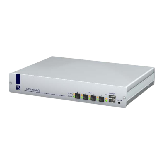
- Page 1 G&D DVIMUX4-DL-PS/2 Installation and Operation...
-
Page 2: About This Manual
About this manual This manual has been carefully compiled and examined to the state-of-the-art. G&D neither explicitly nor implicitly takes guarantee or responsibility for the qual- ity, efficiency and marketability of the product when used for a certain purpose that differs from the scope of service covered by this manual. -
Page 3: Table Of Contents
Contents Contents Safety instructions .................... 1 The »DVIMUX4-DL-PS/2« KVM switch ............2 Package contents ....................2 Installation ....................... 3 Overview of the interfaces .................. 3 Setting up the device ..................3 Connecting the console devices ................4 Connecting the computers .................. 5 Connecting the power supply ................ -
Page 4: Safety Instructions
Safety instructions Safety instructions Please read the following safety instructions carefully before you start operating the G&D product. The instructions well help in avoiding damages to the product and in preventing possible injuries. Keep this manual handy for all persons who will be using this product. Follow all warnings or operating instructions which are on the device or stated in this user manual. -
Page 5: The "Dvimux4-Dl-Ps/2" Kvm Switch
The »DVIMUX4-DL-PS/2« KVM switch The »DVIMUX4-DL-PS/2« KVM switch The DVIMUX4-DL-PS/2 KVM switch enables you to operate up to four computers via one console. The console has to be supplied with a PS/2 keyboard, a PS/2 mouse and a digital and/or analog monitor. The computers connected to the KVM switch are operated at the installed console. -
Page 6: Installation
Installation Installation Overview of the interfaces Front panel of the KVM switch The front panel of the KVM switch provides two USB interfaces to connect a USB keyboard and/or mouse. NOTE: The PS/2 interfaces to connect the console keyboard and mouse (at the back panel of the KVM switch) and the USB interfaces at the front panel of the device can be used at the same time. -
Page 7: Connecting The Console Devices
Installation Connecting the console devices NOTE: Connect the cables of the console and the computers preferably block by block and from the bottom up. By doing so, you will avoid already connected cables blocking your view of the interfaces. Monitor 1 DVI-I CPU 1.1 DVI-I CPU 2.1 DVI-I CPU 3.1... -
Page 8: Connecting The Computers
Installation Connecting the computers IMPORTANT: KVM cable sets are required to connect the computers to the KVM switch. A list of the available KVM cable sets can be found on page 30. Assign the KVM cable sets to the different computers and place them ready for installation. -
Page 9: Connecting The Power Supply
Installation Connecting the power supply Monitor 1 DVI-I CPU 1.1 DVI-I CPU 2.1 DVI-I CPU 3.1 DVI-I CPU 4.1 CPU 1 CPU 2 CPU 3 CPU 4 Keyb. Mouse Speaker Line In Keyb. Mouse Line In Keyb. Mouse Line In Keyb. -
Page 10: Further Information
Further information Further information Support of digital and analog video signals Computers that provide digital or analog video signals can be connected to the KVM switches of the DVIMUX4-DL series. The signal type (digital or analog) that is transmit- ted from computer to KVM switch is displayed unaltered on the connected monitor. Uniform signal type within one video channel Install a console monitor that can display the uniform signal type of the computer’s video channels (only digital or analog). -
Page 11: Initiation
Initiation Initiation Turn on the Power switch on the back panel of the KVM switch. As soon as the device is supplied with power, the green User LED lights up. The KVM switch is now ready for operation. Status displays The LEDs on the front panel of the device enable you to control the operational status at all time. -
Page 12: Switching Between The Computers
Switching between the computers Switching between the computers The user can either use the four buttons on the front panel of the device or key com- binations to switch between different computers. Keyboard and mouse inputs are forwarded to the active computer. The video signal of the active computer is displayed at the console monitor. -
Page 13: Switching Via Serial Device
Switching between the computers Select keys »Back« step key »Forward« step key 1 ... 4 NUM 1 ... 4 NUM 9 NUM 0 A ... D F1 ... F4 How to use step keys to switch to a certain channel: Hotkey+»Back«... -
Page 14: Switching Commands
Switching between the computers Switching commands The following commands are provided for switching the channel: Command Channel <! switch to previous channel >! switch to next channel ADVICE: Use the » « command to show the currently accessing channel. NOTE: The serial device carries out the command directly after it has been sent. -
Page 15: Configuration
Configuration Configuration The configuration of the KVM switch can optionally be changed in the setup mode or in the setup menu: Enable the setup mode using the console keyboard. You can change the configura- tion via special setup keys. ... -
Page 16: Operating The Setup Mode
Configuration Operating the setup mode The setup mode can be enabled using the console keyboard. After enabling, the con- figuration of the KVM switch can be changed by using various step keys. NOTE: Only one setup function can be performed after the calling of the setup mode. If you want to perform more functions, please restart the setup mode. -
Page 17: Operating The Setup Menu
Configuration Operating the setup menu The setup menu provides a convenient alternative to view and edit the configuration of the KVM switch. The switch can be operated through the setup menu which both easy operation and adjustment of several settings within a session. The setup menu can be operated via any terminal emulator (e.g. - Page 18 Configuration The setup menu lists all settings in tabular form: Settings for DVIMUX4-DL Show System Info ... Hotkey: Ctrl Double Hotkey: Select Key: 1..4 Hotkey Delay: Set System Defaults Select Ch.1 after Power up: Select Channel via Front Button: Select Channel via Hotkey: Select Channel via Step Key: 9 | 0 Service RS232 Bitrate:...
-
Page 19: Configuration Settings
Configuration Configuration settings Using single or double hotkeys If many application programs with key combinations are operated on one computer or if different G&D devices are used in one cascade, the number of available key combinations might be restricted. In such a case, it is appropriate to apply double hotkeys. How to enable single or double hotkeys: 1. -
Page 20: Changing The Single Hotkey
Configuration Changing the single hotkey Press the hotkey and the Backspace key simultaneously to start the setup mode of the KVM switch. Pressing the hotkey and the select key simultaneously enables the switching of channels. If an application program or another G&D device uses the same hotkey within the cascade, the hotkey can be changed. -
Page 21: Changing The Double Hotkey
Configuration Changing the double hotkey If the use of double hotkeys is enabled (see page 16), press the double hotkey and the Backspace key simultaneously to start the setup mode of the KVM switch. Switching of channels takes place by pressing the double hotkey and a select key at the same time. -
Page 22: Changing The Select Keys
Configuration Changing the select keys In the default settings, use the enabled select keys to switch between the com- puters that are connected to the KVM switch. For instance, you can switch to computer 2 by pressing Hotkey+2 (default: Ctrl+2 How to choose a different select key set: 1. -
Page 23: Disabling/Enabling The Hotkey Delay
Configuration Disabling/Enabling the hotkey delay Press the Hotkey+Backspace (default: Ctrl+Backspace ) key combination for seven sec- onds in order to start the setup mode in the default settings. You can disable the hotkey delay if you want to start the setup mode immediately after pressing the key combination. -
Page 24: Resetting The Default Settings
Configuration Resetting the default settings This function resets the default settings of the KVM switch. IMPORTANT: Performing this function reactivates the default settings of the KVM switch as shown on page 12! How to reset the default settings: Hotkey+Backspace Ctrl+Backspace 1. -
Page 25: Auto-Accessing The First Channel
Configuration Auto-accessing the first channel Usually, after turning on the device, the recently active channel is accessed. The set- ting can be changed so that the computer connected to the first channel is automati- cally accessed when the device is turned on. How to disable/enable the automatic access of the first channel after booting: NOTE: The option to automatically access the first channel after booting the device... -
Page 26: (De)Activating The Switching Via Hotkeys
Configuration (De)activating the switching via hotkeys In the defaults, you can use hotkeys to switch between the computers. If desired, you can deactivate this kind of switching in the setup menu. How to enable/disable the switching via hotkeys: NOTE: Use the setup menu to (de)activate the switching via hotkeys. 1. -
Page 27: (De)Activating The Switching Via Step Keys
Configuration (De)activating the switching via step keys Instead of using hotkeys to switch to one of the channels connected to the KVM switch, you can also use step keys to switch the channels in ascending or descending order. NOTE: The use of step keys is disabled in the default settings. After enabling the step keys, you can use the following key combinations to switch channels in ascending or descending order: ... -
Page 28: Changing The Bit Rate Of The Service Port
Configuration Changing the bit rate of the Service port The Service port of the KVM switch can be used both for operating the setup menu and for switching the channels with a serial device. The Service port transfers a certain amount of data per time unit. The bitrate is given in bit/s. -
Page 29: Changing The Standard Mode Of The Service Port
Configuration Changing the standard mode of the Service port The Service port of the KVM switch can be used both for operating the setup menu and for switching the channels with a serial device. IMPORTANT: Depending on the purpose of use, the KVM extender distinguishes between the modes listed below. -
Page 30: Changing The Scan Code Set Of A Ps/2 Keyboard
Configuration Changing the scan code set of a PS/2 keyboard If a key is pressed on the PS/2 keyboard, the keyboard processor sends a data packet that is called scan code. The two common scan code sets (sets 2 and 3) contain dif- ferent scan codes. -
Page 31: Selecting The Ps/2 Keyboard Type
Configuration Selecting the PS/2 keyboard type In addition to standard PS/2 keyboards, the KVM switch also supportsPixelPower Clar- ity (blue) and SKIDATA1 keyboards. Select the keyboard type if you want to use such a keyboard at the console. NOTE: The PS/2 keyboard type can only be selected in the setup menu. How to select the PS/2 keyboard type: 1. -
Page 32: Enabling Or Resetting A Ps/2 Mouse
Configuration Enabling or resetting a PS/2 mouse Compared to USB mouses, PS/2 mouses do not support hot plug technology. You can therefore insert the PS/2 plug during operation, but it may be possible that the computer does not detect the input device. To enable or reset the PS/2 mouse, the KVM switch can be used to send a special command to the computer. -
Page 33: Order Numbers
Order Numbers Order Numbers DVIMUX4-DL-PS/2 DVIMUX4-DL-USB KVM SWITCHES KVM SWITCHES A210 0098 DVIMUX4-DL-PS/2 A210 0099 DVIMUX4-DL-USB A210 0100 A210 0101 DVIMUX4-DL-USB-RM DVIMUX4-DL-PS/2-RM A210 0102 A210 0104 DVIMUX4-DL-MC2-USB DVIMUX4-DL-MC2-PS/2 A210 0103 DVIMUX4-DL-MC2-PS/2-RM A210 0105 DVIMUX4-DL-MC2-USB-RM A210 0106 DVIMUX4-DL-MC3-PS/2 A210 0108 DVIMUX4-DL-MC3-USB A210 0107 A210 0109 DVIMUX4-DL-MC3-USB-RM DVIMUX4-DL-MC3-PS/2-RM... -
Page 34: Technical Data
Technical Data Technical Data General features of the series DVIMUX4-DL-PS/2 SERIES see variant features No. of video sources per computer/console: Console Connections per device: Connection: directly at the device see variant features Interfaces Video: for console PS/2 keyboard/mouse: 2 ×... -
Page 35: Individual Variant Features
Technical Data Individual variant features DVIMUX4-DL-PS/2 No. of video sources per computer/console: Interfaces Video: 1 × DVI-I socket for console Interfaces Video: 4 × DVI-I socket for computer Power supply Current consumption (max.): 115mA@240VAC; 210mA@100VAC Power consumption (max.): 13,4W@240VAC; 12,9W@100VAC Casing Dimensions (W ×... - Page 36 Technical Data DVIMUX4-DL-MC4-PS/2 No. of video sources per computer/console: Interfaces Video: 4 × DVI-I socket for console Interfaces Video: 4 × 4 DVI-I sockets for computer Power supply Current consumption: 230mA@240VAC; 530mA@100VAC Power consumption: 32,4W@240VAC; 32,6W@100VAC Casing Dimensions (W × H × D): 270 ×...
- Page 37 Notes G&D DVIMUX4-DL-PS/2 · 34...
- Page 38 Notes 35 · G&D DVIMUX4-DL-PS/2...
- Page 39 Notes G&D DVIMUX4-DL-PS/2 · 36...
- Page 40 Guntermann & Drunck GmbH Dortmunder Str. 4a 57234 Wilnsdorf Germany Phone +49 2739 8901-100 +49 2739 8901-120 http://www.GDsys.de sales@GDsys.de...
Need help?
Do you have a question about the G&D DVIMUX4-DL-PS/2 and is the answer not in the manual?
Questions and answers