Advertisement
Quick Links
Advertisement

Related Manuals for Guntermann & Drunck G&D DL-MUX4


Summary of Contents for Guntermann & Drunck G&D DL-MUX4
- Page 1 G&D DL-MUX4 Installation and Operating Guide...
-
Page 2: About This Manual
About this manual This manual has been carefully compiled and examined to the state-of-the-art. G&D neither explicitly nor implicitly takes guarantee or responsibility for the qual- ity, efficiency and marketability of the product when used for a certain purpose that differs from the scope of service covered by this manual. -
Page 3: Table Of Contents
Contents Contents Safety instructions .................... 1 The KVM switch »DL-MUX« ................2 Scope of delivery ....................2 Installation ....................... 3 Overview of the interfaces .................. 3 Setting up the device ..................3 Connecting the console devices ................4 Connecting the computers .................. 5 Connecting up to two local networks .............. - Page 4 Contents Configuration settings (continued) Changing the scancode set of a PS/2 keyboard ..........27 (De)activating the switching ................ 28 (De)activating channels ................28 Activating or resetting a PS/2 mouse ............29 Resetting the default settings ............... 30 Further information ..................31 Mixed mode of digital and analog video signals ..........
-
Page 5: Safety Instructions
Safety instructions Safety instructions Please read the following safety instructions carefully before you start operating the G&D product. The instructions well help in avoiding damages to the product and in preventing possible injuries. Keep this manual handy for all persons who will be using this product. Follow all warnings or operating instructions which are on the device or stated in this user manual. -
Page 6: The Kvm Switch "Dl-Mux
The KVM switch »DL-MUX« The KVM switch »DL-MUX« The KVM switch DL-MUX4 enables the user to operate up to four computers through one console. NOTE: If the computers to be operated are provided with several video outputs, a multi-channel variant can be used to output each video signal separately on a con- sole monitor. -
Page 7: Installation
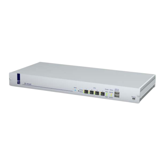
Installation Installation Connect the cables preferably block by block and from the bottom up. By doing so, you will avoid already connected cables blocking your view of the interfaces. Overview of the interfaces Front panel of the KVM switch The front panel of the KVM switch provides two USB 2.0 interfaces to connect any USB devices. -
Page 8: Connecting The Console Devices
Installation Connecting the console devices RS232 Monitor DVI-I CPU 1 DVI-I CPU 2 DVI-I CPU 3 Mouse Network B CPU In 1 CPU In 2 CPU In 3 Keyb. USB K/M Speaker PS/2 K/M USB K/M PS/2 K/M USB K/M PS/2 K/M USB K/M Network A... -
Page 9: Connecting The Computers
Installation Connecting the computers NOTE: The interfaces listed below are available for each computer to connect a maximum of four computers to the KVM switch. The DVI interfaces are located at the top of the back panel. The other interfaces are located block by block at the bottom. -
Page 10: Connecting Up To Two Local Networks
Installation Connecting up to two local networks If desired, connect the network interfaces to up to two local networks to access the Config Panel web application from the networks and to send SNMP traps or syslog messages to these networks. RS232 Monitor DVI-I CPU 1... -
Page 11: Start-Up
Start-up Start-up Switch on the power buttons on the back panel of the KVM switch. If the device is supplied with power, at least one of the Power LEDs lights up. The KVM switch is ready for operation when the Status|Ready LED blinks. -
Page 12: Switching Between The Computers
Switching between the computers Switching between the computers A computer, which is connected to the KVM switch, can be accessed by pressing either the buttons at the device or configured select or step keys or via a serial interface. NOTE: After you purchased and activated the DevCon function, you can also switch via SNMP and the Config Panel web application (see page 11). -
Page 13: Switching Via Step Keys
Switching between the computers Switching via step keys Alternative to using select keys to switch between channels connected to the KVM switch is to use the step keys to switch the channels in ascending or descending order. IMPORTANT: The active step keys depend on the selected select keys. The following table lists the step keys depending on the active select keys. -
Page 14: Switching Commands
Switching between the computers Switching commands The following commands are provided for switching the channel: Command Channel <! switch to previous channel >! switch to next channel NOTE: The serial device carries out the command directly after it is sent. A message (see below) informs the serial device concerning the success or failure of the switching of channels. -
Page 15: Switching Via Web Application
Switching between the computers Switching via web application NOTE: After you purchased and activated the DevCon function, you can also switch the channels via SNMP and the Config Panel web application. A computer, which is connected to the KVM switch, can be accessed via Config Panel web application. -
Page 16: Initial Configuration Of The Network Settings
Initial configuration of the network settings Initial configuration of the network settings A basic requirement to access the web application is to configure the network set- tings of the KVM switch on which the web application is operated. The following table lists the default settings of the Network A network interface: IP allocation: static IP address:... - Page 17 Initial configuration of the network settings 8. Use th Interface A and/or Interface Be paragraphs to enter the following data: Operational mode: Use the pull-down menu to select the operational mode of Interface A Interface B Off: switch network interface off. ...
-
Page 18: Using The Reset Button
Using the Reset button Using the Reset button The front panel of the device provides the Reset button (between the Identification LED and the CPU LEDs). This button enables you to reset the default settings as well as to temporarily deacti- vate the netfilter rules. -
Page 19: Temporarily Deactivating The Netfilter Rules
Using the Reset button Temporarily deactivating the netfilter rules The default status of the KVM switch allows all network computers to access the IP address of the device (open system access). The web application enables you to create netfilter rules to control the access to the device. -
Page 20: Configuration
Configuration Configuration The configuration of the KVM switch can optionally be carried out in the setup menu or via the Config Panel web application: Enable the setup mode using the console keyboard. You can change the configura- tion via special setup keys. ... -
Page 21: Operating The Setup Mode
Configuration Operating the setup mode The configuration of the KVM switch can either be changed in the setup mode or in the Config Panel web application. The setup mode can be enabled using the console keyboard. After enabling, the con- figuration of the KVM switch can be changed by using various step keys. -
Page 22: Basic Operation Of The Web Application
Configuration Basic operation of the web application The Config Panel web application provides a graphical user interface to configure and monitor the KVM switch. The web application can be applied on a computer with installed Java Runtime Envi- ronment. Use one of the supported web browsers to run the application. NOTE: Information regarding the system requirements, the required configuration of the network interfaces of the KVM switches and the application of the web... -
Page 23: User Authentication Against The Web Application
Configuration User authentication against the web application After the certificates have been authenticated, the login box appears. How to log in to the Config Panel web application: 1. Enter the following data in the login box: Username: Enter your username. Password: Enter your user account password. -
Page 24: Configuration Settings
Configuration Configuration settings Activating or deactivating the hotkey delay Press the Hotkey+Backspace (default: Ctrl+Backspace ) key combination for seven sec- onds in order to start the setup mode in the default settings. You can disable the hotkey delay if you want to start the setup mode immediately after pressing the key combination. -
Page 25: Changing The Hotkey
Configuration Changing the hotkey The hotkey is used to switch to a computer or to call the setup mode: Switch to a particular computer by pressing the hotkey and a select key at the same time. Start the setup mode by pressing the hotkey and the setup key at the same time. NOTE: Ctrl The hotkey... -
Page 26: Changing The Select Key Sets
Configuration Changing the select key sets The select keys (set » 1…4 «) are activated in the default settings to switch between the computers that are connected to the KVM switch. EXAMPLE: Press Hotkey+2 (default: Ctrl+2 ) to switch to computer 2. If one of the key combinations of the select key set interferes with a key combination of an installed application program, the hotkey (see page 21) and the select key set can be changed. -
Page 27: Changing The Setup Key
Configuration Changing the setup key The hotkey to call the setup mode consists of at least one hotkey modifier (see Changing the hotkey on page 21) and an additional setup key, which can be selected from a given range of keys. Both the hotkey modifier ( Ctrl ) and the setup key (... -
Page 28: Support For Multimedia And Special Sun Keys
Configuration Support for Multimedia and special Sun keys NOTE: This function can only be (de)activated in the web application. Various manufacturers added special keys to the standard keyboards. Some keyboards are provided with multimedia keys which enable the user to easily operate special multimedia functions of the computer. - Page 29 Configuration If the console is provided with a Sun keyboard, use the Solaris Shortcut Keys of this keyboard after enabling. When using a standard keyboard, these functions can be performed by using the key combinations listed below: Key combination Solaris Shortcut Key of the Sun Keyboard Ctrl+Alt+F2 Again Ctrl+Alt+F3...
-
Page 30: Support For Special Keyboards
Configuration Support for special keyboards NOTE: This function can only be (de)activated in the web application. The KVM switch supports the special functions of some special keyboards. Activate the support of such keyboards in the KVM switch. How to (de)activate the support for special keyboards: KVM switches >... -
Page 31: Changing The Scancode Set Of A Ps/2 Keyboard
Configuration Changing the scancode set of a PS/2 keyboard If a key is pressed on the PS/2 keyboard, the keyboard processor sends a data packet that is called scan code. The two common scan code sets (sets 2 and 3) contain dif- ferent scan codes. -
Page 32: (De)Activating The Switching
Configuration (De)activating the switching A computer, which is connected to the KVM switch, can be accessed by pressing either the buttons at the device or configured hotkeys (select or step keys). It can also be accessed via a serial interface. After you purchased and activated the DevCon function, you can use the Config Panel web application or SNMP to switch to the protocol. -
Page 33: Activating Or Resetting A Ps/2 Mouse
Configuration Activating or resetting a PS/2 mouse NOTE: The following functions can only be carried out in the setup mode. Compared to USB mouses, PS/2 mouses do not support hot plug technology. You can therefore insert the PS/2 plug during operation, but it may be possible that the computer does not detect the input device. -
Page 34: Resetting The Default Settings
Configuration Resetting the default settings This function resets the default settings of the KVM switch. By performing this func- tion, the default settings of the KVM switch mentioned on page 16 are reactivated. How to reset the default settings: 1. Press Hotkey+Backspace (default: Ctrl... -
Page 35: Further Information
Further information Further information Mixed mode of digital and analog video signals Computers that provide both digital and analog video signals can also be connected to the KVM switch. When connecting such a computer, please consider that the video signal type (DVI dual link, DVI single link or analog), which is transmitted from the respective computer to the KVM switch, is connected through to the attached monitor without modification. -
Page 36: Pin Assignment Of The Rs232 Socket
Further information Pin assignment of the RS232 socket The devices of the DL-MUX series provide an RS232 socket. The following figures shows the pin assignments of the RS232 socket: The table shows how the different conduits of the data connection are assigned to the according pins: Pin no. -
Page 37: Technical Data
Technical data Technical data General features DL-MUX SERIES see specific features No. of video sources per computer/console: Console Connections per device: Connection: directly at device see specific features Interfaces Video: for console PS/2 keyboard/mouse: 2 × PS/2 socket USB keyboard/mouse: 2 ×... -
Page 38: Specific Features
Technical data Casing Material: anodised aluminium see specific features Dimensions (W × H × D): see specific features Weight: see specific features Operating environment Temperature: Air humidity: < 80%, non-condensing Conformity CE, RoHs Specific features DL-MUX No. of video sources per computer/console: Interfaces... - Page 39 Technical data DL-MUX-MC3 No. of video sources per computer/console: Interfaces Video: 3 × DVI-I socket for console Interfaces Video: 3 × DVI-I socket per computer Current consumption max.: 100-240VAC/60-50Hz, 0.6-0.3A Power consumption Standby: 12,3 W @ 240 VAC; 11,7 W @ 100 VAC Operation: 30,2 W @ 240 VAC;...
- Page 40 Guntermann & Drunck GmbH Dortmunder Str. 4a 57234 Wilnsdorf Germany Phone +49 2739 8901-100 +49 2739 8901-120 http://www.GDsys.de sales@GDsys.de...
Need help?
Do you have a question about the G&D DL-MUX4 and is the answer not in the manual?
Questions and answers