Advertisement
Advertisement
Table of Contents

Related Manuals for TRUELOOK TrueDeter PTZ


Summary of Contents for TRUELOOK TrueDeter PTZ
- Page 1 TrueDeter Installation Manual...
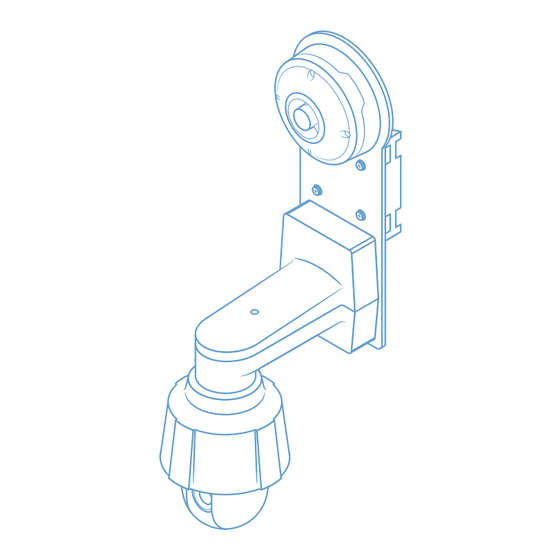
- Page 2 Getting Started Assembled Unit...
-
Page 3: Online Resources
Getting Started Unlimited Support If you have any questions or issues with your TrueLook system, please don’t hesitate to contact our Customer Support team. 833-878-3566 (Option 2) Phone Email support@truelook.com You can also submit a support request online at: support.truelook.com/contact-support... -
Page 4: Hardware Packing List
Getting Started Hardware Packing List Camera System [1x] Purchased models come pre-assembled. Control Box [1x]... - Page 5 Getting Started Pole Mounting Hardware Steel Straps [4x] Wall Mounting Hardware L Brackets [4x] Mounting Feet [4x] Screws [4x] Flat Washers [4x] Lock Washers [4x] Nuts [4x] Warning: This equipment contains flashing lights, which may induce epileptic seizures in at-risk individuals.
-
Page 6: Pole Mounting
Installation Pole Mounting Camera System Step 1 Thread steel straps through top and bottom of pole mount on back of plate. Tighten each strap around pole using drill with 5/16 hex Step 2 head driver bit (not included). - Page 7 Installation Step 3 Trim steel straps to desired length using tin snips (not included). Remove pendant mount top by using T30 Torx Step 4 screwdriver (not included) to loosen screw.
- Page 8 Installation Step 5 Push camera up into pendant housing and rotate a quarter turn until it snaps into place, aligning with screw holes. Step 6 Secure camera to pendant housing by tightening screws using T30 Torx screwdriver.
- Page 9 Installation Step 7 Plug connector coming from camera mount into top of camera. Connector should snap firmly into place. Warning: Removal of black fiber port cap can lead to water damage. Replace cap if it has been removed. It should snap firmly in place.
- Page 10 Installation Control Box Step 1 Thread steel straps through pole mounting hardware on top and bottom of control box. For large diameter poles For small diameter poles...
- Page 11 Installation Tighten each strap around pole using drill with 5/16 hex Step 2 head driver bit. Step 3 Trim steel straps to desired length using tin snips.
-
Page 12: Wall Mounting
Installation Wall Mounting Camera System Step 1 Attach wall mounting hardware to sides of pole mount with screw, washer, lock washer, and nut, using drill with Phillips #2 bit (not included) on screws and pliers (not included) to hold nuts tight. - Page 13 Installation Step 2 Using hardware appropriate for your mounting surface, attach system to wall. Remove pendant mount top by using T30 Torx Step 3 screwdriver (not included) to loosen screw. Step 4 Push camera up into pendant housing and rotate a quarter turn until it snaps into place, aligning with screw holes..
- Page 14 Installation Step 5 Secure camera to pendant housing by tightening screws using T30 Torx screwdriver. . Step 6 Plug connector coming from camera mount into top of camera. Connector should snap firmly into place.
- Page 15 Installation Warning: Removal of black fiber port cap can lead to water damage. Replace cap if it has been removed. It should snap firmly in place. Step 7 Secure pendant mount top by placing it back on and tightening screw.
- Page 16 Installation Control Box Step 1 Remove pole mounting hardware from back of control box using drill with Phillips #2 bit.
- Page 17 Installation Attach mounting feet to back of control box using Step 2 same screws and drill with Phillips #2 bit. Tab on mounting foot nests within slot on control box. Step 3 Using hardware appropriate for your mounting surface, attach control box to wall.
- Page 18 Powering Connecting & Powering Twist protective plug caps off bottom of control box. Step 1 The caps should hang freely. Connect camera system to control box by Step 2 plugging in both connectors of braided cable coming from camera. Connectors go into either socket and should snap firmly in place.
- Page 19 Powering Step 3 Twist protective plug caps on connectors up into bottom of control box. This will create a watertight seal. Warning: Do not use tools to tighten cap. Cap should be snug, but will not be flush against the enclosure. Connect control box to power.
-
Page 20: Verifying Camera Operation
10 minutes for it to come online. Then, use the link on the back of the manual to view the camera and verify its functionality. If you don’t see the camera in the TrueLook Platform, contact Customer Support for assistance. -
Page 21: Troubleshooting
Final Setup Troubleshooting If something seems wrong with the system, it may be necessary to troubleshoot. Camera Not Operating Properly Check that the camera cable connectors are securely fastened into the control box. Check that the power source is supplying power. If your system is still not functioning properly, please contact Customer Support for further assistance. - Page 22 For the most efficient response from our team, include the following in your email: Company name Project name Contact person for installation issues The following photographs: A. Your whole TrueLook solution: the camera, what it’s mounted to, and any accessories B. Close-ups of mounting C. Close-ups of connections...
- Page 23 Notes...
-
Page 24: Accessing Your Camera
Accessing Your Camera TRU 24019-11 D5 © TrueLook Construction Cameras MAN100630 Manual-TrueDeter PTZ...
Need help?
Do you have a question about the TrueDeter PTZ and is the answer not in the manual?
Questions and answers