Table of Contents
Advertisement
Advertisement
Table of Contents

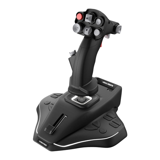
Summary of Contents for WinWing URSA MINOR-Fighter-Joystick R
- Page 1 URSA MINOR-Fighter-Joystick R User Manual V1.0 2024.08...
-
Page 2: Table Of Contents
Contents: Packing List ......................1 1. Parameters ................................2 1.1. Performance Parameters ...............2 1.2. Applicable Model .................4 1.3. External Dimensions ................4 1.4. Mounting Dimensions ................5 2. Functions ....................... 6 2.1. Buttons and Functions ................6 2.2. Method of Adjustment ................. 9 3. -
Page 3: Packing List
② Packing List ④ J5-BASE-BLACK+JGRIP-F1-R(1#) USB Cable (2#) Tool kit T1:2.0mm Hex Wrench T2:2.5mm Hex Wrench Accessories M3*6 Hexagon Socket Cap Screws (3#) -
Page 4: Parameters
1.Parameters 1.1.Performance Parameters 15° -15° 15° -15° *The X/Y axes have a movable angle of ±15°, with an operating force of approximately 6 newtons. - Page 5 -20° 20° *The Z axis has a rotational angle of ±20°, with a rotational torque of approximately 4 kgf·cm.
-
Page 6: Applicable Model
*The potentiometer axis has an available physical travel of 38mm, with an operating force ranging from 35 to 135gf. 1.2.Applicable Model Use Independently. 1.3.External Dimensions L*W*H:227mm*217mm*246mm; Wight:1.05Kg=2.31lb... -
Page 7: Mounting Dimensions
1.4.Mounting Dimensions... -
Page 8: Functions
Note: The screw insertion depth must be greater than 6mm and less than 10mm. Screws must be self-supplied and are not included in the accessory kit. *Unit: mm 2.Functions 2.1.Buttons and Functions... - Page 9 4095 4095 1st 2nd 65535 *The grip features a vibration function with adjustable amplitude levels from 0 to 255.
- Page 10 65535 65535 SIider 4095 *14 key switches with press force of 250gf and press travel of 0.25mm. Note: Please press the center area of the keycap. Pressing too close to the edge may cause the keycap to get stuck.
-
Page 11: Method Of Adjustment
* Ambient Light: 1 channel of cool white light: Compatible status light logic: In upgrade mode, it cycles on and off (on for 1 second, off for 1 second). In work mode, it flashes upon power-up (on for 1 second, off for 1 second) for 5 times, then it is controlled by software and turns off when the computer enters sleep mode. - Page 12 *Adjustable Z-Axis: Use the T1 (2.0mm) hex wrench to tighten the screw, which will lock the Z-axis in place. Removing the screw allows for Z-axis rotation of ±20°. X/Y Axis Damping Adjustment:...
-
Page 13: Assemble And Disassembly Of Components
* Turn the product upside down, release the latch, and remove the bottom cover. * As shown in the figure, use the T2 (2.5mm) hex wrench: Adjust screws A and B simultaneously to control the Y-axis damping (increase damping clockwise, decrease counterclockwise); by adjusting screw C, you can control the X-axis damping (increase damping clockwise, decrease counterclockwise). -
Page 14: Mounting Methods
5.Mounting Methods 5.1.Desktop Mounting * Remove the protective film from the bottom silicone pad as shown in the figure, and place it directly on the desk. Note: Keep the desktop flat and clean. The glass and marble desktop will provide a better skid-proof function Note: The shell of this product is made entirely of plastic, structured with 3 layers vertically stacked. -
Page 15: Cascading
Note: The screws must be inserted to a depth greater than 6mm but less than 10mm. You will need to provide the screws yourself, as they are not included in the accessory pack. 5.3.Cascading... -
Page 16: Calibration
6.Calibration 6.1.Calibration of X and Y axis joystick ①Open SimAppPro, click the device icon to enter the test page, and then click “Calibration”; ②On the calibration page, click the following two buttons to start calibration, and then move the joystick to the full travel; ③After completing the movement, allow the joystick to naturally return to the center, and... -
Page 17: Calibration Of Z Axis
then click the two buttons shown in the following figure; ④After finishing step 3, the calibration of joystick is completed. Go back to the test page to check if the data is normal, if not, repeat the calibration steps. 6.2.Calibration of Z axis ①Open SimAppPro, click the device icon to enter the test page, and then click “Calibration”option;... - Page 18 ②On the calibration page, click the following button to start calibration, and then rotate Z axis to the full travel; ③After finishing step 2, make the Z axis return to the center naturally, and then click the following button;...
-
Page 19: Calibration Of Rx And Ry Axis Mini Joystick
④After finishing step 3, the calibration of Z axis is completed. Go back to the te st page to check if the data is normal, if not, repeat the calibration steps. 6.3.Calibration of Rx and Ry axis mini joystick ①Open SimAppPro, click the device icon to enter the test page, and then click “Calibration”option;... - Page 20 ③After finishing step 2, make the mini joystick return to the center naturally, and then click the following two buttons;...
-
Page 21: Calibration Of The Slider Axis Sliding Block
④After finishing step 3, the calibration of mini joystick is completed. Go back to the test page to check if the data is normal, if not, repeat the calibration steps. 6.4.Calibration of the Slider Axis Sliding Block ①Open SimAppPro, click the device icon to enter the test page, and then click “Calibration”option;... - Page 22 ③After finishing step 2, click the following button;...
- Page 23 ④After finishing step 3, the calibration of Slider axis sliding block is completed. Go back to the test page to check if the data is normal, if not, repeat the calibration steps.
- Page 24 *内容如有更新,恕不另行通知。 Please note that if there are any updates to the content, we will not notify separately. 成都翼胜科技有限责任公司 WWW.WINWING.CN INFO@WINWING.CN 成都市郫都区现代工业港长生桥路 1111 号 19 栋 High-tech International Enterprise Zone No.19 Building,Changshengqiao Road 1111#, Pidu District, Chengdu,China 610000...


Need help?
Do you have a question about the URSA MINOR-Fighter-Joystick R and is the answer not in the manual?
Questions and answers