Table of Contents
Advertisement
Quick Links
Advertisement
Table of Contents

Related Manuals for FlexRadio FLEX-5000


Summary of Contents for FlexRadio FLEX-5000
- Page 1 ® Version 2.0 www.flex-radio.com sales@flex-radio.com (512) 535 - 4713...
- Page 2 FlexRadio Systems. Information contained in this document may contain technical inaccuracies or typographical errors. Information may be changed or updated without notice. FlexRadio Systems may make improvements and/or changes in the materials at any time without notice. All materials are provided "as is". FlexRadio Systems makes no representations or warranties, expressed or implied to the accuracy of the copyrighted materials.
-
Page 3: Table Of Contents
(12) FlexWire™ Peripheral Interface Bus...................10 (13) Line-Out and Line-In Audio Jacks..................11 (14) Balanced Line Input......................11 Connecting to a Balanced XLR Connector....................12 (15) PTT Jack........................12 (16) RF Ground Terminal......................13 FLEX-5000C COMPUTER CONNECTIONS AND INITIALIZATION........13 Computer Connections....................13 Wireless Keyboard and Mouse....................13 F5K-M2.0/4 © 2003-2010 FlexRadio Systems... - Page 4 4 OPERATION................51 POWER-UP PROCEDURE.....................52 POWER-DOWN PROCEDURE..................53 TUNING METHODS......................54 Spectrum Drag and Click......................54 Mouse Wheel........................54 Mouse Wheel Hover.......................54 Spectrum Click Tuning......................54 Keyboard Keys........................55 USB Tuning Knob........................55 VOICE OPERATION.....................56 CW OPERATION......................60 Initial Settings......................61 Internal Keyer......................62 External Keyer......................64 F5K-M2.0/4 © 2003-2010 FlexRadio Systems...
- Page 5 (20) ATU AND BYP.....................98 (21) AF (AUDIO FREQUENCY GAIN)................98 (22 AND 22B) AGC-T (AGC THRESHOLD)..............98 (23) DRIVE (TRANSMITTER POWER OUTPUT/TUNE POWER)........98 (24 AND 24B) AGC (AUTOMATIC GAIN CONTROL)............99 (25 AND 25B) PREAMP....................99 (26 AND 26B) SQL (SQUELCH)...................99 F5K-M2.0/4 © 2003-2010 FlexRadio Systems...
- Page 6 Simple........................120 Expert........................121 (39) ATU........................123 Operating Mode............................123 Tuning Options.............................123 SWR Threshold............................124 Tuner Feedback............................124 VOLTAGE AND TEMPERATURE INFORMATION............124 7 SETUP FORM................125 GENERAL TAB......................126 Hardware Config Sub-Tab....................126 Radio Model............................126 FLEX-5000 Config..........................126 Receive Only............................127 DDS..............................127 Options Sub-Tab......................128 Options...............................129 F5K-M2.0/4 viii © 2003-2010 FlexRadio Systems...
- Page 7 Noise Blanker............................148 Noise Blanker 2............................148 Window ..............................149 Image Reject Sub-Tab....................151 Expert..............................151 Transmit Rejection..........................152 Keyer Sub-Tab......................153 CW Pitch.............................153 Connections............................153 Options...............................154 Signal Shaping.............................155 Break In..............................155 AGC/ALC Sub-Tab......................156 AGC..............................156 Leveler..............................157 ALC..............................157 TRANSMIT TAB......................158 Profiles...............................158 Transmit Filter............................159 DC Block.............................159 Tune..............................159 F5K-M2.0/4 © 2003-2010 FlexRadio Systems...
- Page 8 Test..............................174 ID AS..............................175 RTTY Offset............................175 TESTS TAB........................176 Two Tone Test:.............................176 Audio Balance Test..........................176 Signal Generator..........................177 Enable HW Signal Generator........................178 8 DRIVER CONTROL PANEL............179 GLOBAL SETTINGS....................180 Bus Settings......................180 DPC Latency Checker....................181 DEVICE SETTINGS....................182 General........................182 Firmware Loader......................183 F5K-M2.0/4 © 2003-2010 FlexRadio Systems...
-
Page 9: Preface
If you have any ideas on how to improve the FLEX-5000, please feel free to contact us, or better still, to join our email reflector (see http://kc.flex-radio.com/KnowledgebaseArticle50024.aspx). Not only is the FLEX-5000 a software defined radio;... -
Page 10: Acknowledgments
Acknowledgments FlexRadio Systems could not be as successful, nor could the FLEX-5000 radio be what it is today without the many selfless contributions from our users all over the world. These contributions have spanned and continue to span improvements to our hardware and software, ranging from bug reports and feature requests to actual design and implementation of certain functionality. -
Page 11: Using This Manual In Its Pdf Form
If the hyperlink has been previously clicked, it will be shown in magenta instead of blue. [The rest of this page has been left blank intentionally] Adobe and Reader are registered trademarks of Adobe Systems, Inc. F5K-M2.0/4 © 2003-2010 FlexRadio Systems... -
Page 12: Reference To Software Controls
Color Buttons are used as color selectors. You can pick a generic color (yellow or green) or even make your own using the drop down menu. Up/Down controls are similar to a Text Box, but are limited to numeric input. They also have arrows for simple increment/decrement behavior. F5K-M2.0/4 xvii © 2003-2010 FlexRadio Systems... -
Page 13: Hardware Installation
(Other items may be included that are not listed above) The FLEX-5000 power cable is unterminated on one end so that you can adapt it to various DC power connectors, such as Anderson Power Poles, Banana plugs, screw terminals or spade lugs. Connect the 2 red wires to the positive terminal and the 2 black wires to the negative terminal of your power supply For the FLEX-5000A, you may need to acquire a 4-pin to 6-pin cable if using a laptop. -
Page 14: Location Considerations
RFI getting into the computer. High quality, quad-shielded FireWire cables up to 10m in length have been used successfully with the FLEX-5000. Ensure convenient access to the back panel . The FLEX-5000 back panel is where most of your ... -
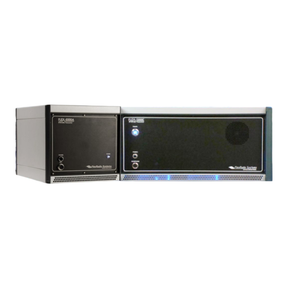
Page 15: Front Panel
Front Panel Figure 2: FLEX-5000A (top) and FLEX-5000C (bottom) Front Panel [The rest of this page has been left blank intentionally] Identifiers refer to the same controls and connectors on the FLEX-5000A and C models. F5K-M2.0/4 © 2003-2010 FlexRadio Systems... -
Page 16: Led Push Button Power Switch
C H A P T E R (1) LED Push Button Power Switch The FLEX-5000 uses a delayed start push button to power up the radio. To turn on the radio, push the button in fully and release. After a few seconds you will hear the ... -
Page 17: Internal Speaker (Flex-5000C Only)
C H A P T E R Note: The FLEX-5000 has a 20 dB microphone preamp built in. If you do not require this additional gain, you may want to try using either the unbalanced Line-In (13) or Balanced Line Input (14) jack on the back panel (see pages 6 and 10). -
Page 18: Back Panel
FLEX-5000A; the left half has all the connections for the built in computer. The FLEX-5000 has the ability to connect up to three different antennas to the receiver and or transmitter and up to two additional receive only antennas. All of these are assignable on a per band basis. -
Page 19: Primary Antenna Ports (Ant1, Ant2 & Ant3)
(4)-(5) Dedicated Transverter Connections The FLEX-5000 has been designed to support transverters through both a 28 MHz and/or 144 MHz IF interface. XVTX/COM outputs a 28 MHz IF signal, adjustable up to +5 dBm to drive external ... -
Page 20: Dual Ieee 1394 Firewire Jacks
(7) Dual IEEE 1394 FireWire Jacks The FLEX-5000 has two 400 Mb/s 6-pin IEEE 1394 FireWire jacks. These are 1394a connections not the 1394b (FireWire 800) type which run at 800 Mb/s. Connect the ferrite core end of the supplied 6-pin FireWire cable to either of these two jacks and connect the other end to FLEX-5000A: your computer’s FireWire jack (the host controller). -
Page 21: Straight Key Or Paddles (Key)
(even for modern amplifiers) to insert the circuit shown in Figure 4 below between each of TX1, 2 and/or 3 and your amplifier(s). Figure 4: Protective PTT Circuit Between TX1-3 and Amplifier F5K-M2.0/4 © 2003-2010 FlexRadio Systems... -
Page 22: External Frequency Reference Input
A family of FlexWire peripherals will be forthcoming from FlexRadio Systems. This is not another “CAT” port, but an industry standard bidirectional communications bus based on the I (pronounced “I squared C”) protocol along with AF I/O lines. -
Page 23: Line-Out And Line-In Audio Jacks
C H A P T E R (13) Line-Out and Line-In Audio Jacks Consumer level (-10 dBV) audio connections. Audio levels can be set on the FLEX-5000 Mixer Form (see page 118). Line-Out can drive external sound card-based applications if VAC is not, or cannot be used. It ... -
Page 24: Connecting To A Balanced Xlr Connector
(-) To interface this type of microphone to the FLEX-5000 a balanced XLR (female) to balanced ¼” TRS (male) cable is necessary, which should be wired as shown in Figure 5a. You can also connect audio processing equipment using a similar cable. -
Page 25: Rf Ground Terminal
Connect to the single point ground system in your shack. Alternatively, if you have no single point grounding system, ground the FLEX-5000 to the metal chassis of your computer with a low impedance ground strap, such as a 1” braid or copper strip (the screws that hold the computer power supply in place make an excellent grounding point). -
Page 26: Computer Speakers
Note: Do not confuse these with the internal speaker or external speakers you may have connected to the Powered Speakers jack (11), which are strictly used for receive audio by the FLEX-5000. Network Connection WARNING! Install an anti-virus protection application before connecting to networks or the Internet. -
Page 27: Set Up And Configure The Computer
The operating system is preinstalled but in a “sealed” state. It is not usable until you accept the End User Licensing Agreement contained in the operating system. FlexRadio is not in control of this process since the software use agreement is between you, the end user, and Microsoft. -
Page 28: Set Your Time Zone And The System Date/Time
Drivers and documentation for your computer system board as well as software, firmware and drivers used by FlexRadio are stored in your Installer Library. These items are preinstalled and are provided as backup copies in the event you need to remove/reinstall any of them. The folder is located at the root level of the C: drive. -
Page 29: Hard Drive Restore Process
. It contains a complete copy of the originally shipped factory software. In the event you have a virus infection, major problem with the operating system, accidental folder deletion or other major disturbance, it is possible to completely reinstall the operating system, application programs, FlexRadio programs and tools from this restore partition. - Page 30 (SSB): Flat Response 10 Hz to 20 kHz, 3-band or 10-band Software EQ Order IMD Better than 33 dB below PEP @14.2 MHz 100 W PEP Microphone Impedance 600 Ohms (200 to 10 kOhms) Balanced Line In Impedance 600 Ohms (200 to 10 kOhms) F5K-M2.0/4 © 2003-2010 FlexRadio Systems...
-
Page 31: Flex-5000C Embedded Computer Specifications
External (not supplied); VGA or (dual) DVI; Resolution: 1024 x 768 min/2048 x 1536 Monitor(s) Software Operating System Windows XP Professional PowerSDR Latest version installed Collection of Ham Radio Software installed, including vCOM virtual serial port Other software [The rest of this page has been left blank intentionally] F5K-M2.0/4 © 2003-2010 FlexRadio Systems... -
Page 32: Flex-5000 Architecture
H A R D W A R E I N S T A L L A T I O N C H A P T E R FLEX-5000 Architecture The FLEX-5000 full duplex/triplex architecture is shown in Figure 6 below. F5K-M2.0/4 © 2003-2010 FlexRadio Systems... -
Page 33: Declarations Of Conformity
I N S T A L L A T I O N C H A P T E R Declarations of Conformity The FLEX-5000 complies with FCC Part 97 rules for the Amateur Radio Service. EU Compliance F5K-M2.0/4 © 2003-2010 FlexRadio Systems... -
Page 34: Software Installation
(bus) as the FLEX-5000. Both of these devices use the FireWire bus extensively and performance of both will be degraded significantly. Also, do not connect both a FLEX-3000 and a FLEX-5000 to the same computer. The drivers cannot differentiate between the two and erratic behavior may occur. -
Page 35: Collecting Your Information
Make sure the FLEX-5000A is turned off (Power switch LED is not illuminated, see Figure 2 on page 3). Alternatively, disconnect the FireWire cable between your FLEX-5000 and the computer. It is also a good idea to close all other applications. - Page 36 C H A P T E R Figure 8: FlexRadio InstallShield Wizard – Proprietary Software License There are two license agreements. The first is this End User License Agreement (EULA) for FlexRadio proprietary software, which covers those parts of the software that are proprietary to FlexRadio Systems.
- Page 37 I N S T A L L A T I O N C H A P T E R Figure 9: FlexRadio InstallShield Wizard – GNU Public Software License The second EULA refers to those parts of the software which are covered by the GNU Public License.
- Page 38 I N S T A L L A T I O N C H A P T E R Figure 10: FlexRadio InstallShield Wizard – Customer Information Enter you information and click Next to select the setup type (Figure 11).
- Page 39 I N S T A L L A T I O N C H A P T E R Figure 11: FlexRadio InstallShield Wizard – Setup Type Select Complete to install all the software . Click Next to select the radio(s) (Figure 12).
- Page 40 Select FLEX-3000/5000 to install the software it requires. You may also elect to install at the same time the software for any other FlexRadio Systems radio(s) you own. Click Next and the InstallShield Wizard will indicate that it is ready to install (Figure 13).
-
Page 41: Installing The Firewire Driver
InstallShield Wizard will proceed to install the FireWire Driver. Installing the FireWire Driver Before the FlexRadio FireWire Driver can be installed your radio must be turned off. You will see a reminder to check that it is. (Figure 14). Figure 14: FlexRadio InstallShield Wizard - Reminder to Turn Off Radio Make sure your radio is indeed turned off and click Continue. - Page 42 I N S T A L L A T I O N C H A P T E R Figure 15: FlexRadio Driver Setup Wizard - Welcome Click Next to select the destination folder for the Driver (Figure 16). [The rest of this page has been left blank intentionally] F5K-M2.0/4...
- Page 43 I N S T A L L A T I O N C H A P T E R Figure 16: FlexRadio Driver Setup Wizard - Destination Location The driver will be installed in the default location shown. Although we recommend you accept this default location, you may change it;...
- Page 44 I N S T A L L A T I O N C H A P T E R Figure 17: FlexRadio Driver Setup Wizard - Additional Tasks We recommend that you elect to Create a desktop icon as shown for easy access to the Driver's Control Panel.
- Page 45 I N S T A L L A T I O N C H A P T E R Figure 18: FlexRadio Driver Setup Wizard - Ready to Install To review and/or change your installation settings, click Back. Otherwise, click Install and the Driver Setup Wizard will proceed to install all the required software (Figure 19).
- Page 46 I N S T A L L A T I O N C H A P T E R Figure 19: FlexRadio Driver Setup Wizard - Installing While the software is installing the Driver Setup Wizard will display a progress bar. If a Software Installation warning appears, click Continue Anyway to proceed.
- Page 47 I N S T A L L A T I O N C H A P T E R Figure 20: FlexRadio Driver Setup Wizard - Installation Complete Click Finish to exit the FlexRadio Driver Setup Wizard. [The rest of this page has been left blank intentionally] F5K-M2.0/4...
-
Page 48: Installing Powersdr
When completed you will see a screen requesting you to turn on your radio 30-60 seconds after restarting your computer (Figure 22). Figure 22: FlexRadio InstallShield Wizard - Notice to Power-Up Radio After Reboot Click OK and the FlexRadio InstallShield Wizard will indicate that Installation is Complete (Figure 23). F5K-M2.0/4 © 2003-2010 FlexRadio Systems... -
Page 49: Power Up The Flex-5000A To Complete The Installation
C H A P T E R Figure 23: FlexRadio InstallShield Wizard – Installation Complete Click Finish to exit the FlexRadio InstallShield Wizard. You will then be instructed to restart your computer (Figure 24). Figure 24: Instruction to Restart Computer Click Yes to restart your computer now. -
Page 50: Windows Vista And Windows 7
Windows XP Three drivers will be loaded in succession: first the FlexRadio FLEX-5000, followed twice by the FlexRadio MIDI. We will describe in detail how to proceed for the FlexRadio FLEX-5000. These steps are identical for each of the other two. - Page 51 Figure 26 above may not show up in some systems. Figure 27: Found New Hardware Wizard - Installing the Software The Found New Hardware Wizard will show that you are trying to install a FlexRadio Systems FLEX- 5000. Select the option Install the software automatically (Recommended). Click Next to continue.
- Page 52 As previously mentioned, the Found New Hardware Wizard will again be displayed, but now for the FlexRadio MIDI. Follow the same steps as previously to install the MIDI driver. And finally, the Found New Hardware Wizard will display one more time, again for the FlexRadio MIDI. Follow the same steps as previously to install the MIDI driver.
-
Page 53: Powersdr Setup & Configuration
Chapter PowerSDR Setup & Configuration Setup Wizard Power up the FLEX-5000 and start up the PowerSDR application using the shortcut on your Desktop (or click on Start All Programs FlexRadio Systems FlexRadio Systems Software 2.n PowerSDR v2.n.n). When you run a new release of PowerSDR for the first time an optimization routine will run and the screens shown in Figure 29 will appear. - Page 54 If you wish to run FFTW again, delete this file from that directory and start up PowerSDR. PowerSDR next transfers your FLEX-5000's calibration data to your computer. This only happens once, the first time you run a new release of PowerSDR.
- Page 55 C O N F I G U R A T I O N C H A P T E R Figure 31: PowerSDR Setup Wizard - Radio Model Select the FLEX-5000 radio model as shown in Figure 31. Click the Next button to continue to Figure 32. Note: If you are running without a radio, e.g.
- Page 56 The Setup Wizard is now complete. Click the Finish button to complete the wizard. Note: If you forgot to power up the FLEX-5000 before starting PowerSDR, a communication error message will be displayed and PowerSDR will offer the ability to start in demo mode. Click No to close PowerSDR, power up the FLEX-5000 and restart PowerSDR.
-
Page 57: Configuration
C H A P T E R Configuration Before operating the FLEX-5000 you will need to configure the Mixer and Antenna settings. If you have not yet done so, start up PowerSDR to open the Front Console, but do not yet click on the Start button. -
Page 58: Audio Mixer
Audio Mixer The FLEX-5000 input and output audio channels are managed with an audio mixer, much the same as for your Windows sound card(s). To configure the audio mixer, click on Mixer on the Front Console menu (Figure 35). -
Page 59: Antenna Port And External Keying Lines
Transmit: ANT1 (default), ANT2 or ANT3 Earlier versions of the FLEX-5000, with the HRFIO board Assembly Number (ASSY) 27 installed instead of the later HRFIO board ASSY 34, do not have ANT1 available as an option for Receiver 2. You can check which board is installed in your FLEX- 5000 by opening the Setup Form –... -
Page 60: Ready To Start Operating
Ready to Start Operating You are now ready to use your FLEX-5000. Click on Start on the Front Console and you should hear receive audio. If you do not, double check all your connections and settings (especially for the Mixer and Antenna forms). -
Page 61: Operation
Chapter Operation This chapter is intended to provide the user with a clear understanding of how the FLEX-5000 should be used when performing basic operations such as Powering Up or making a voice, CW or digital transmission. Note 1: For consistency we will use the same control identifiers as used in Figure 46 on page 73. -
Page 62: Power-Up Procedure
At this point you should see the Windows opening screen. After waiting at least 30 seconds, start up PowerSDR. It will automatically recognize the FLEX- 5000 driver. You are now ready to operate. [The rest of this page has been left blank intentionally] F5K-M2.0/4 © 2003-2010 FlexRadio Systems... -
Page 63: Power-Down Procedure
1. Stop PowerSDR by clicking on the Start/Stop button. 2. Close PowerSDR by clicking on the “X” in the upper right hand corner of the Front Console. 3. Press the FLEX-5000 illuminated Power switch to turn off the transceiver. CAUTION: Make sure PowerSDR is shut-down before turning off the radio. -
Page 64: Tuning Methods
VFO will immediately tune to the frequency of the selected signal. Chapter 5 on page 73 explains all the Front Console controls in detail. The identifiers between parentheses refer to the control identifiers used there. F5K-M2.0/4 © 2003-2010 FlexRadio Systems... -
Page 65: Keyboard Keys
(All these documents and more can be found by searching for either PowerMate or ShuttlePro on our Knowledge Center at http://kc.flex-radio.com/search.aspx) [The rest of this page is intentionally left blank] F5K-M2.0/4 © 2003-2010 FlexRadio Systems... -
Page 66: Voice Operation
All screenshots of the Front Console are displayed with the Default skin. Your Front Console may look differently if you have selected a different skin (see page 163 for more information on how to select skins). F5K-M2.0/4 © 2003-2010 FlexRadio Systems... - Page 67 ATU, select Automatic on the ATU Form (39) and then click the TUN (19) button. See the section on the ATU Form on page 123 for more on how to use the ATU. [The rest of this page has been left blank intentionally] F5K-M2.0/4 © 2003-2010 FlexRadio Systems...
- Page 68 50 ohm load with a low SWR. Failing to do so may damage the FLEX-5000 output transistors. Press the Push-to-talk button on the microphone or click the MOX (16) button and speak into the microphone to transmit your voice.
- Page 69 DX (8) control and the associated slider to increase the compression in 1 dB steps. This must be done carefully as adding too much compression can result in high levels of distortion. [The rest of this page has been left blank intentionally] F5K-M2.0/4 © 2003-2010 FlexRadio Systems...
-
Page 70: Cw Operation
Figure 46 on page 73 and for clarity we have left out any identifiers of controls not referenced. [The rest of this page has been left blank intentionally] F5K-M2.0/4 © 2003-2010 FlexRadio Systems... -
Page 71: Initial Settings
If you are not using the internal ATU then connect a 50 ohm dummy load, or ensure that the antenna presents a 50 ohm load with a low SWR. Failing to do so may damage the FLEX5000 output transistors. F5K-M2.0/4 © 2003-2010 FlexRadio Systems... -
Page 72: Internal Keyer
If using PowerSDR’s internal keyer, open the Setup Form – DSP Tab, Keyer Sub-Tab shown in Figure 39 below. Several of the controls in this form are also available in the Mode Specific Controls – CW (8) section on the Front Console. [The rest of this page has been left blank intentionally] F5K-M2.0/4 © 2003-2010 FlexRadio Systems... - Page 73 CW Speed (8) on the Front Console. If Disable Monitor is unchecked, you should hear the side tone. Verify with the TX Meter (4) set to Fwd Pwr that there is forward power. F5K-M2.0/4 © 2003-2010 FlexRadio Systems...
-
Page 74: External Keyer
Figure 40: CWX Form 1. Click on one of the numbered buttons to start transmitting the corresponding CW sequence. Verify with the TX Meter (4) set to Fwd Pwr that there is forward power. F5K-M2.0/4 © 2003-2010 FlexRadio Systems... -
Page 75: Third Party Cw Program
Internal Keyer controls. If the CW program runs on one computer and PowerSDR on another, two physical serial ports are indeed required (one on each computer). The ports are interconnected as described. F5K-M2.0/4 © 2003-2010 FlexRadio Systems... - Page 76 Tune to the desired frequency using one of the methods outlined in the Tuning Methods section above. Select either CWL or CWU (6) and proceed with the QSO. [The rest of this page has been left blank intentionally] Kenwood is a registered trademark of Kenwood Corporation F5K-M2.0/4 © 2003-2010 FlexRadio Systems...
-
Page 77: Digital Operation
COM6/COM26. (In other words COM-A = COM26 and COM-B = COM6). If the digital mode software and PowerSDR run on separate computers, two sound cards (one on each computer) are indeed required and they are interconnected as described. F5K-M2.0/4 © 2003-2010 FlexRadio Systems... - Page 78 Figure 46 on page 73 and for clarity we have left out any identifiers of controls not referenced. [The rest of this page has been left blank intentionally] F5K-M2.0/4 © 2003-2010 FlexRadio Systems...
- Page 79 If you want your digital mode software to control PowerSDR, then in the Setup Form - CAT Control tab, select COM26 as the Cat Control port for PowerSDR to connect to and check Enable CAT (see page 172). [The rest of this page has been left blank intentionally] F5K-M2.0/4 © 2003-2010 FlexRadio Systems...
- Page 80 50 ohm load with a low SWR. Failing to do so may damage the FLEX-5000 output transistors. 7. If using CAT control, click on the Transmit button of your digital mode program. It should switch PowerSDR to transmit.
- Page 81 Hint 2: Please check Knowledge Center (http://kc.flex- radio.com/search.aspx) for more articles on how to use PowerSDR with various digital mode programs. [The rest of this page has been left blank intentionally] F5K-M2.0/4 © 2003-2010 FlexRadio Systems...
-
Page 82: Front Console
The exact behavior of many of these controls can be configured with the Setup Form. Note 2: The lower part of the font console will only be visible if you have the second receiver (RX2) installed. F5K-M2.0/4 © 2003-2010 FlexRadio Systems... -
Page 83: Vfo A
With Split on, the transmit frequency is displayed in VFO B (VFO B TX indicator is red) RX2 Off means that either the second receiver is not installed or it is installed, but switched off. F5K-M2.0/4 © 2003-2010 FlexRadio Systems... -
Page 84: Tuning Controls
Tune Step by clicking the buttons, clicking the mouse wheel button, or using Ctrl + Left/Right Arrow. The band text returns by turning RX2 off, or leaving RX2 on, but turning split and/or multiRX off. F5K-M2.0/4 © 2003-2010 FlexRadio Systems... -
Page 85: Vfo B
(two) drop down boxes at the top. The text display below the meter selections shows the digital data for either the receiver or the transmitter (Signal strength in Figure 50 above). The lower display at the bottom of this section shows F5K-M2.0/4 © 2003-2010 FlexRadio Systems... -
Page 86: Rx1 And Rx2 Meters
Sig Avg (Signal Average): Calculates the true RMS power in dBm of a time-averaged signal within the passband, as measured at the selected FLEX-5000 antenna port. ADC L (Analog To Digital Left): Calculates the level in dBFS (decibel full scale) of the Left ... -
Page 87: (5 And 5B) Band Selection & Band Stacking Memories
Then change the frequency, mode, and filter to the desired settings (the frequency must be in the band selected). Finally click the band button again to save the values. F5K-M2.0/4 © 2003-2010 FlexRadio Systems... -
Page 88: (6 And 6B) Mode Selection
SAM: Synchronous (PLL) Amplitude Modulation SPEC (RX1 only): Spectrum mode (DC IF, max bandwidth determined by the selected sampling rate) DIGL: Digital Lower Side Band (Enables VAC if VAC Auto Enable is engaged, see page 139) F5K-M2.0/4 © 2003-2010 FlexRadio Systems... -
Page 89: (7 And 7B) Filter Controls
DRM: Digital Radio Mondiale (requires licensed external demodulator software not available from FlexRadio Systems; Enables VAC if VAC Auto Enable is engaged, see page 139) Hotkeys are available in the Setup-Form, Keyboard Tab to cycle through the various modes using the keyboard (see page 170). -
Page 90: Variable Filter Buttons
Width: Widens the filter as the slider is moved right, and narrows the filter as it is moved left. The behavior of this control is set in the Setup Form – General Tab, Filter Sub-Tab (page 133). F5K-M2.0/4 © 2003-2010 FlexRadio Systems... -
Page 91: Mode Specific Controls
Having said that, the software gain works very well in many setups. The setting is optimal when the peak reading on the TX Mic Meter reads just below 0 dB (see page 77 above) F5K-M2.0/4 © 2003-2010 FlexRadio Systems... - Page 92 PowerSDR and other third party (digital) programs. See also the Setup Form – Audio Tab, VAC Sub-Tab described on page 138. VAC is not automatically enabled for phone modes, even if Auto Enable has been checked on the VAC Sub-Tab. [The rest of this page has been left blank intentionally] F5K-M2.0/4 © 2003-2010 FlexRadio Systems...
-
Page 93: Cw Controls
Enable has been checked on the VAC Sub-Tab. Break In: check the Enabled box to activate Break In for the internal keyer. Set the delay in the Delay text box. See also page 155. F5K-M2.0/4 © 2003-2010 FlexRadio Systems... -
Page 94: Digital Controls
Mono/Stereo: sets the VAC interface to operate either mono or stereo. This can be of importance, depending on your third party software. (E.g. MixW requires the mono setting, whereas DREAM requires stereo). [The rest of this page has been left blank intentionally] F5K-M2.0/4 © 2003-2010 FlexRadio Systems... -
Page 95: (9 And 9B) Display Controls
Setup Form-Display Tab (see page 141). AVG must be enabled for the 0 Beat VFO Control to be available. Peak: click to hold the peak value for each frequency in the display. [The rest of this page has been left blank intentionally] F5K-M2.0/4 © 2003-2010 FlexRadio Systems... -
Page 96: Display Type Descriptions
0 Hz line to the left or right margin (1.2 kHz tone in USB mode with a 2.7 kHz filter shown). [The rest of this page has been left blank intentionally] F5K-M2.0/4 © 2003-2010 FlexRadio Systems... -
Page 97: Panadapter
This gives a much more complete picture of the surrounding area in the band, especially when there is abundant signal activity (e.g. contest and DX situations). [The rest of this page has been left blank intentionally] F5K-M2.0/4 © 2003-2010 FlexRadio Systems... -
Page 98: Waterfall
The Waterfall Display can be customized on the Setup Form- Display Tab This allows custom setting of the dynamic range and coloring for the display. (See the Setup Form-Display Tab on page 143 for more details.) [The rest of this page has been left blank intentionally] F5K-M2.0/4 © 2003-2010 FlexRadio Systems... -
Page 99: Histogram
DX (page 82) or equalization (page 109). The time base can be adjusted on the Setup Form- Display Tab (see page 141). [The rest of this page has been left blank intentionally] F5K-M2.0/4 © 2003-2010 FlexRadio Systems... -
Page 100: Phase
With RX2 installed and on, the RX2 available display types are Panadapter and Waterfall. The screen then shows the RX1 display type above the RX2 display type, as illustrated in Figure 66. [The rest of this page has been left blank intentionally] F5K-M2.0/4 © 2003-2010 FlexRadio Systems... -
Page 101: Cursor And Peak Position
Together with the AVG control they allow easy measurement of signals on the display. For example, in Figure 67 the cursor position is offset -10219.9 Hz from the VFO frequency and is at 14.244780 MHz. The horizontal line of the crosshairs is at -96.0 dBm. F5K-M2.0/4 © 2003-2010 FlexRadio Systems... -
Page 102: Multirx Controls
If you activate MultiRX and RX2 simultaneously, these vertical sliders will effect both the RX2 audio and the second RX1 channel audio simultaneously. You can then also use the RX2 Audio Controls to adjust RX2's audio independently (see Figure 75 on page 100). F5K-M2.0/4 © 2003-2010 FlexRadio Systems... -
Page 103: (11 And 11B) Dsp Controls
Wearing headphones increases the effect of the spatial separation. Note: BIN is not available when operating FMN, AM or SAM. [The rest of this page has been left blank intentionally] F5K-M2.0/4 © 2003-2010 FlexRadio Systems... -
Page 104: Vfo Controls
VFO A frequency by the amount shown in Hz while leaving the transmit frequency intact. Click the 0 button next to the RIT button to clear the RIT control to F5K-M2.0/4 © 2003-2010 FlexRadio Systems... -
Page 105: Cpu
Note 2: To use PowerSDR without any hardware attached to the PC you must disable PTT. On the Setup Form-General Tab, select either Disable PTT on the Options Sub-Tab, or Demo/None on the Hardware Config Sub-Tab F5K-M2.0/4 © 2003-2010 FlexRadio Systems... -
Page 106: Mut (Mute)
The TUN button will stay enabled after a tune cycle with the ATU set to Memory or Full. The button will become deselected when the ATU is bypassed, whether it be due to tuning to another band or manually selecting Bypass in the ATU Form (see page 123). F5K-M2.0/4 © 2003-2010 FlexRadio Systems... -
Page 107: Atu And Byp
The control doubles in function as the power level setting for the TUN (Tune) button described above. The Tune power may be adjusted while the TUN button is activated or by using the control on the Setup Form-Transmit Tab. F5K-M2.0/4 © 2003-2010 FlexRadio Systems... -
Page 108: (24 And 24B) Agc (Automatic Gain Control)
Squelch can be very useful to remove all noise from CW signals, especially in narrow filter settings. [The rest of this page has been left blank intentionally] (27) Antenna Selection Display Figure 73: Antenna Selection Display F5K-M2.0/4 © 2003-2010 FlexRadio Systems... -
Page 109: Date/Time Display
Mute: Mutes the second receiver's audio. (31) Setup Form The Setup Form contains numerous controls for everything from the hardware configuration to transmit settings. Please refer to the Setup Form chapter on page 125 for more detailed information. F5K-M2.0/4 © 2003-2010 FlexRadio Systems... - Page 110 Each of these menu items opens a form, which is used while operating. Please refer to the next chapter on the following page for more detailed information on each one. [The rest of this page has been left blank intentionally] F5K-M2.0/4 © 2003-2010 FlexRadio Systems...
-
Page 111: Operating Forms
76). For ease of reference, the numerical identifiers from the previous chapter on the Front Console are repeated in this chapter. Additionally, the key combination Ctrl-Shift-I activates the voltage and temperature form (see page 124) Figure 76: Operating Form Identifiers [The rest of this page has been left blank intentionally] F5K-M2.0/4 © 2003-2010 FlexRadio Systems... -
Page 112: Memory Form
Clicking the OK button will save the information shown above into the memory database before closing the form. Clicking Cancel simply closes the form (the data is not saved). [The rest of this page has been left blank intentionally] F5K-M2.0/4 © 2003-2010 FlexRadio Systems... -
Page 113: Recall
Close on Recall to close the Memory Form when clicking Recall. Delete: Click the Delete button to remove a memory from the database. A prompt will be shown to prevent unintended loss of memories. F5K-M2.0/4 © 2003-2010 FlexRadio Systems... -
Page 114: Wave Form
The Wave form allows the user to Record and Playback either the post-processed audio (see page 108) of the current station, or up to 192 kHz bandwidth (as determined by the audio sample rate setting) of pre-processed IF (I and Q) “audio” (see page 108) from the FLEX-5000. Note: The recorded audio is always played back through PowerSDR. -
Page 115: Playlist
Quick Rec will overwrite any audio file previously recorded in this way. These two buttons perform the same function as the Record () and Play () buttons on the Front Console (see page 97). [The rest of this page has been left blank intentionally] F5K-M2.0/4 © 2003-2010 FlexRadio Systems... -
Page 116: Record Options
Sample Rate Sets the sample rate at which the wave file will be recorded. [The rest of this page has been left blank intentionally] F5K-M2.0/4 © 2003-2010 FlexRadio Systems... -
Page 117: Equalizer Form
Low, Mid and High audio bands. The Preamp applies gain across the whole audio spectrum. Easily compare the audio with and without the equalizer using the Enabled check box. The Reset button will reset all of the sliders to the 0 dB position. F5K-M2.0/4 © 2003-2010 FlexRadio Systems... -
Page 118: 10-Band Equalizer
The 10-Band Equalizer offers a finer degree of audio frequency control than does the 3-band equalizer. You may want to use this equalizer if the 3-band equalizer does not give you the result you want. [The rest of this page has been left blank intentionally] F5K-M2.0/4 © 2003-2010 FlexRadio Systems... -
Page 119: Xvtrs Form
End Frequency (MHz): The upper frequency bound for the transverter. RX Gain (dB): Amount of gain to apply to the incoming signals to compensate for gain within the transverter. Please note that this is still in development. F5K-M2.0/4 © 2003-2010 FlexRadio Systems... - Page 120 Power control on this form (see above). Otherwise, the Tune Power setting on the Setup Form – Transmit Tab (page 158) will be used. [The rest of this page has been left blank intentionally] F5K-M2.0/4 © 2003-2010 FlexRadio Systems...
-
Page 121: Cwx Form
Drop Delay: This control specifies the amount of time in ms that the semi-break in keying will wait before dropping the transmitter when there is no keying occurring. F5K-M2.0/4 © 2003-2010 FlexRadio Systems... -
Page 122: Cwx Memories
(see Morse Definition Editor on page 116). Characters that are undefined have no dots and dashes and are simply sent as a space. [The rest of this page has been left blank intentionally] F5K-M2.0/4 © 2003-2010 FlexRadio Systems... -
Page 123: Keyboard And Extended Controls
Hitting Alt 1 to Alt 9 or right clicking on the message number button will cause the numbered message memory to be copied into the unsent area just as if you had typed it. The or ditto character is ignored in the keyboard mode. F5K-M2.0/4 © 2003-2010 FlexRadio Systems... -
Page 124: Morse Definition Editor
The editor dialog example above shows the ‘]’ character being changed to send didahdidah which is the German code for ä (umlaut a). When your definition appears to be correct, click the Save button and the definition file will be resaved to the disk. F5K-M2.0/4 © 2003-2010 FlexRadio Systems... - Page 125 PowerSDR and click CWX. The editor makes simple changes relatively easy to do. [The rest of this page has been left blank intentionally] F5K-M2.0/4 © 2003-2010 FlexRadio Systems...
-
Page 126: Mixer
C H A P T E R (37) Mixer Figure 87: Audio Mixer Form The Mixer controls the audio lines into and out of the FLEX-5000. In essence it is no different than the usual Windows sound card mixer. Input The FLEX-5000 has four possibles sources of input audio. -
Page 127: Antenna
You could damage your radio and void your warranty. Note: If you switch between the Expert and Simple levels your settings will be remembered should you decide to change back. [The rest of this page has been left blank intentionally] F5K-M2.0/4 © 2003-2010 FlexRadio Systems... -
Page 128: Simple
OUT and connect Receiver 1 to RX1 IN. Earlier versions of the FLEX-5000, with the HRFIO board Assembly Number (ASSY) 27 installed instead of the later HRFIO board ASSY 34, do not have ANT1 available as an option for Receiver 2. You can check which board is installed in your FLEX- 5000 by opening the Setup Form –... -
Page 129: Expert
In addition to the selections discussed for the Simple complexity level, the Expert level offers the Band control. For each band, set the various controls as desired and these settings will automatically be enabled when operating on that band. F5K-M2.0/4 © 2003-2010 FlexRadio Systems... - Page 130 To quickly set the various controls, make the selections first for the Simple complexity level. Then switch to Expert and adjust where necessary for those bands that need adjustment from the original settings. [The rest of this page has been left blank intentionally] F5K-M2.0/4 © 2003-2010 FlexRadio Systems...
-
Page 131: Atu
Use TUN: Check to transmit a carrier at the power level set by the Tune Power control on the Setup Form-Transmit Tab (see page 158). The ATU will use this carrier when either Memory Tune or Full Tune is selected. F5K-M2.0/4 © 2003-2010 FlexRadio Systems... -
Page 132: Swr Threshold
Celsius and Fahrenheit. Either value may be displayed against a yellow or red background indicating increasing levels of criticality. [The rest of this page has been left blank intentionally] F5K-M2.0/4 © 2003-2010 FlexRadio Systems... -
Page 133: Setup Form
The next time you start- up PowerSDR it will automatically create a new, clean database and read the EEPROM data from your FLEX-5000 to the database. The copy of the database on your desktop is an xml-file named PowerSDR_database_ [date]_[time].xml. -
Page 134: General Tab
Use this selection to choose the hardware (if any) that is connected to the computer running the PowerSDR software. FLEX-5000 Config With FLEX-5000 selected as the Radio Model, this section lists the serial numbers of your FLEX-5000, installed Firmware version and the installed hardware boards of your radio. The ATU (if installed) is marked as present. -
Page 135: Receive Only
ATU and RX2, shown in Figure 93, will only be listed if indeed installed in the radio. RFIO will read HRFIO in later versions of the FLEX-5000. The HRFIO or RFIO board house the antenna switching matrix and the HRFIO has more capabilities than the earlier RFIO (see also page 120). -
Page 136: Options Sub-Tab
However, if you are experiencing low frequency noise, such as spurs that cannot be eliminated with the Spur Reduction (SR) enabled, you might try adjusting the IF. Options Sub-Tab Figure 96: Setup Form - General Tab, Options Sub-Tab F5K-M2.0/4 © 2003-2010 FlexRadio Systems... -
Page 137: Options
Systems recommends using the Normal setting, if you are experiencing audio glitches or are using a slower machine, selecting Above Normal or High might improve the performance of the software. Note that FlexRadio Systems does not recommend using the Real Time setting as this could cause timing problems with the operating system. -
Page 138: Click Tune Offsets (Hz)
Mouse Tune Step: When checked, clicking the mouse wheel (middle click) will cycle through the tune steps. Wheel Tunes VFOB (red x-hairs): Check to have the mouse wheel tune VFO B when the red cross-hairs are showing (Split or MultiRX enabled). F5K-M2.0/4 © 2003-2010 FlexRadio Systems... -
Page 139: Keyboard
VFO frequency due to accidental key presses. Custom Title Text Enter the text you would like appended to the standard text (FlexRadio Systems PowerSDR vn.n.n) in the title bar of the Front Console. [The rest of this page has been left blank intentionally] F5K-M2.0/4... -
Page 140: Calibration Sub-Tab
If you decide to proceed, tune your radio to a known accurate frequency source (e.g. WWV), enter the frequency in the Frequency control and click the Start button. [The rest of this page has been left blank intentionally] F5K-M2.0/4 © 2003-2010 FlexRadio Systems... -
Page 141: Filters Sub-Tab
Filter Low and High controls on the front panel. Default Low Cut (Hz): Sets the default low frequency cut-off for the USB/LSB filters. [The rest of this page has been left blank intentionally] F5K-M2.0/4 © 2003-2010 FlexRadio Systems... -
Page 142: Rx2 Sub-Tab
Check Auto Mute RX2 on TX to mute the second receiver RX2 while transmitting. Check Auto Mute RX1 on VFOB TX to mute the first receiver RX1 while transmitting on the RX2 frequency shown in VFO B. [The rest of this page has been left blank intentionally] F5K-M2.0/4 © 2003-2010 FlexRadio Systems... -
Page 143: Navigation
These controls are only functional when using a so called SpaceNavigator as a means to control ™ PowerSDR. Check to have it control the VFO and/or the panadapter. [The rest of this page has been left blank intentionally] SpaceNavigator is a trademark of 3Dconnexion. F5K-M2.0/4 © 2003-2010 FlexRadio Systems... -
Page 144: Audio Tab
Higher sample rates at a given buffer size will reduce the latency in the system, but at the same time widen the filter skirts. It is this trade-off that needs to be made, especially for CW where latency might be more critical. F5K-M2.0/4 © 2003-2010 FlexRadio Systems... -
Page 145: Mic Boost
15ms. We recommend using the default automatic latency setting for best results. [The rest of this page has been left blank intentionally] F5K-M2.0/4 © 2003-2010 FlexRadio Systems... -
Page 146: Vac Sub-Tab
Virtual Cables called Virtual Cable 1 and Virtual Cable 2. Select one of these as the Input and the other as the Output as shown in Figure 106 (see also Digital Operation on page 67). [The rest of this page has been left blank intentionally] F5K-M2.0/4 © 2003-2010 FlexRadio Systems... -
Page 147: Auto Enable
Becomes enabled when Mono/Stereo is checked. Check to combine both L and R stereo input channels. Allow PTT to override/bypass VAC for Phone Check this box if you wish to override or bypass VAC when activating PTT, e.g. to use your microphone. F5K-M2.0/4 © 2003-2010 FlexRadio Systems... -
Page 148: Direct I/Q
Calibrate I/Q: Check to correct the raw I/Q signal and avoid any image signals going to the third-party software. Use RX2: Check to use I/Q signals relating to the second receiver RX2 instead of RX1. [The rest of this page has been left blank intentionally] F5K-M2.0/4 © 2003-2010 FlexRadio Systems... -
Page 149: Display Tab
S E T U P F O R M C H A P T E R Display Tab Figure 110: Setup Form - Display Tab [The rest of this page has been left blank intentionally] F5K-M2.0/4 © 2003-2010 FlexRadio Systems... -
Page 150: Spectrum Grid
CPU Meter (ms): Sets the update rate of the CPU Meter in the lower left of the front console. Raising the value will add more delay between updates while lowering the value will yield faster responses. F5K-M2.0/4 © 2003-2010 FlexRadio Systems... -
Page 151: Waterfall
Average Time (ms): The time over which the signal is averaged when using the SigAvg RX Meter setting. Analog Refresh (ms): Controls how often the analog meter is updated. Digital Refresh (ms): Controls how often the digital meter is updated. F5K-M2.0/4 © 2003-2010 FlexRadio Systems... -
Page 152: Phase Resolution
Expect to see an up to 4 times narrower area of a displayed spike, especially when the displayed frequency span is relatively large in comparison. [The rest of this page has been left blank intentionally] F5K-M2.0/4 © 2003-2010 FlexRadio Systems... -
Page 153: Dsp Tab
Taps determines the length of the Noise filter. Increasing Taps leads to heavier filtering, but also lengthens the time it takes for the filter to adapt. F5K-M2.0/4 © 2003-2010 FlexRadio Systems... -
Page 154: Automatic Notch Filter
The larger the delay, the less the impact on normal speech, and the more likely the filter will be able to concentrate only on longer term coherent signals such as carrier tones. A larger Delay lengthens the time for the ANF to take effect. F5K-M2.0/4 © 2003-2010 FlexRadio Systems... -
Page 155: Use Peak Readings For Tx Meter Dsp Values
3 dB filter width of 1.5*192000/256 ≈ 1125 Hz!! The narrow trace at 48 kHz and 4096 yields a minimum 3 dB filter width of 1.5*48000/4096 ≈ 18 Hz. [The rest of this page has been left blank intentionally] The factor 1.5 is due to the Blackman-Harris windowing function F5K-M2.0/4 © 2003-2010 FlexRadio Systems... -
Page 156: Noise Blanker 2
NB and NB2. The NB Threshold is adjusted to just begin to lower the noise from the pulses, after which NB2 is turned on, with a threshold of four or five less than that of NB. Both F5K-M2.0/4 © 2003-2010 FlexRadio Systems... -
Page 157: Window
In almost all cases Blackman- Harris will be preferred, except possibly for very weak CW signals, where dynamic range is less important than a narrower passband. F5K-M2.0/4 © 2003-2010 FlexRadio Systems... - Page 158 S E T U P F O R M C H A P T E R Figure 120: 25 Hz CW Filter with Hanning (Red) and Blackman-Harris (Blue) Windows [The rest of this page has been left blank intentionally] F5K-M2.0/4 © 2003-2010 FlexRadio Systems...
-
Page 159: Image Reject Sub-Tab
Image Reject Sub-Tab Figure 121: Setup Form - DSP Tab, Image Reject Sub-Tab Note: Your FLEX-5000 is completely calibrated and needs no further adjustments. Expert To reveal the Image Reject controls, check Expert. This will show a warning; click Yes to proceed. You should proceed with caution and only consider doing this if you are an experienced user. -
Page 160: Transmit Rejection
Wideband Image Rejection (WBIR) to adaptively null the receive image across the whole receive bandwidth. This approach is superior to a manual rejection, which nulls the image at one point only. [The rest of this page has been left blank intentionally] F5K-M2.0/4 © 2003-2010 FlexRadio Systems... -
Page 161: Keyer Sub-Tab
Click Tune functions. Connections Figure 124: Connections The internal keyer supports two inputs: the primary and secondary connections. The primary connection will override the secondary. This was designed with the idea that the secondary connection F5K-M2.0/4 © 2003-2010 FlexRadio Systems... -
Page 162: Options
Primary: Select the connection to be used for the primary connection. Selecting Radio allows the use of the jack on the back of the FLEX-5000. Secondary: Select the connection to be used for the secondary connection. Selecting CAT will ... -
Page 163: Signal Shaping
Delay (ms): Sets the amount of time between the last detected input and when the radio will drop back to receive. The smallest possible setting is 10 ms. [The rest of this page has been left blank intentionally] F5K-M2.0/4 © 2003-2010 FlexRadio Systems... -
Page 164: Agc/Alc Sub-Tab
Max Gain (dB): The maximum amount of gain allowed by the AGC system for signals below the AGC threshold. The total AGC gain equals the Max Gain + the Slope (Gain). F5K-M2.0/4 © 2003-2010 FlexRadio Systems... -
Page 165: Leveler
The Compander (DX and CPDR on the Front Console - see Mode Specific Controls – Phone on page 82) work very well together with the ALC to increase average power without overdrive. [The rest of this page has been left blank intentionally] F5K-M2.0/4 © 2003-2010 FlexRadio Systems... -
Page 166: Transmit Tab
Gain, Drive, DX, CPDR, Leveler, and ALC. Click the Save button to save the current profile. You will be prompted for a name. To remove a profile, select it using the drop down menu, and then click the Delete button. [The rest of this page has been left blank intentionally] F5K-M2.0/4 © 2003-2010 FlexRadio Systems... -
Page 167: Transmit Filter
Console (sets the Drive control). Changes made to the Drive level while TUN is active will be reflected in this control. TX Meter: Selects which TX Meter to use when TUN on the Front Console is clicked. F5K-M2.0/4 © 2003-2010 FlexRadio Systems... -
Page 168: Downward Expander/Noise Gate
5. With the DEXP adjusted, speak into the microphone and verify that your voice sounds as natural as possible. There should be a very smooth transition between not speaking and speaking. Fine tune the Threshold and Attenuate(%) settings as desired. F5K-M2.0/4 © 2003-2010 FlexRadio Systems... -
Page 169: Vox
80 would yield roughly 16W when Drive is set to 100. This is useful as it allows the modulation to appear much stronger due to the weaker carrier. [The rest of this page has been left blank intentionally] F5K-M2.0/4 © 2003-2010 FlexRadio Systems... -
Page 170: Standard Tx Profiles
Figure 137. To use one of these, click to select it from the list and then click Import. It will now be active and show up in the Profiles list described on page 158. [The rest of this page has been left blank intentionally] F5K-M2.0/4 © 2003-2010 FlexRadio Systems... -
Page 171: Appearance Tab
If you have downloaded and installed more than just the Default skin, they will be listed in the drop- down box. Select a skin to change the appearance of your Front Console. [The rest of this page has been left blank intentionally] F5K-M2.0/4 © 2003-2010 FlexRadio Systems... -
Page 172: Vfo
Out Of Band: The background color of the VFO band information when outside the amateur radio bands. Background: The background color of the VFO band information when inside the amateur radio bands. F5K-M2.0/4 © 2003-2010 FlexRadio Systems... -
Page 173: Display Sub-Tab
S E T U P F O R M C H A P T E R Display Sub-Tab Figure 141: Setup Form-Appearance Tab, Display Sub-Tab [The rest of this page has been left blank intentionally] F5K-M2.0/4 © 2003-2010 FlexRadio Systems... -
Page 174: Overall Display
Peak Text: The color of the Peak signal location text located below the display. Background: The background color of the Peak signal location text. [The rest of this page has been left blank intentionally] F5K-M2.0/4 © 2003-2010 FlexRadio Systems... -
Page 175: Panadapter
Show Freq. Offset: When selected, the offsets from the Main RX Filter 0 Hz line are shown across the top as opposed to the actual frequencies. [The rest of this page has been left blank intentionally] F5K-M2.0/4 © 2003-2010 FlexRadio Systems... -
Page 176: Meter Sub-Tab
Edge displays an analog edge style meter. Digital Text: The color of the text of the digital meter. Digital Background: The background color of the digital meter. [The rest of this page has been left blank intentionally] F5K-M2.0/4 © 2003-2010 FlexRadio Systems... -
Page 177: Original Style
High Color: The color of the high values of the edge meter’s scale. Background: The background color of the edge meter. Indicator: The color of the indicator in the edge meter. [The rest of this page has been left blank intentionally] F5K-M2.0/4 © 2003-2010 FlexRadio Systems... -
Page 178: Keyboard Tab
Band, Filter, Mode, RIT and XIT up or down using the drop down controls in the respective sections. Note: Choosing any of the arrow keys will require using Alt + [arrow key]. [The rest of this page has been left blank intentionally] F5K-M2.0/4 © 2003-2010 FlexRadio Systems... -
Page 179: Cat Control Tab
In conjunction with null-modem virtual serial port pairs (see pages 65 and 67) interaction is possible with third party programs such as digital mode programs and logging programs. [The rest of this page has been left blank intentionally] F5K-M2.0/4 © 2003-2010 FlexRadio Systems... -
Page 180: Cat Control
Parity: Sets whether to send a parity bit. Data: Sets how many data bits are sent with each byte. Stop: Sets whether to send a stop bit. [The rest of this page has been left blank intentionally] F5K-M2.0/4 © 2003-2010 FlexRadio Systems... -
Page 181: Ptt Control
There are a few programs that expect frequency changes to be broadcast. [The rest of this page has been left blank intentionally] FlexProfiler is a program developed by K5KDN. It is no longer actively supported. F5K-M2.0/4 © 2003-2010 FlexRadio Systems... -
Page 182: Test
Execute button is clicked. Typing a semicolon, the CAT terminator, at the end of the command is optional. The CAT response will appear in the CAT Response text box. Figure 152: CAT Command Tester Form [The rest of this page has been left blank intentionally] F5K-M2.0/4 © 2003-2010 FlexRadio Systems... -
Page 183: Id As
This differs from ClickTune Offsets (see page 130), as the ClickTune Offsets actually change the Front Console VFO frequency, whereas the RTTY Offset only offsets the frequency reported by CAT. [The rest of this page has been left blank intentionally] F5K-M2.0/4 © 2003-2010 FlexRadio Systems... -
Page 184: Tests Tab
Powered Speaker/Line out jack on the Back Panel. [The rest of this page has been left blank intentionally] F5K-M2.0/4 © 2003-2010 FlexRadio Systems... -
Page 185: Signal Generator
DSP. It is used to test PowerSDR. Mode: Select the type of signal to generate. Soundcard means the Signal Generator is turned off and the FLEX-5000 hardware can be used. Note: When finished with the Signal Generator, do not forget to place the Signal Generator back to Soundcard. -
Page 186: Enable Hw Signal Generator
In actual fact, the RF signal is generated using the transmit DSP and sent through the QSE (Quadrature Sampling Exciter), which is then looped back to the QSD (Quadrature Sampling Detector) and the receive DSP. [The rest of this page has been left blank intentionally] F5K-M2.0/4 © 2003-2010 FlexRadio Systems... -
Page 187: Driver Control Panel
The FlexRadio Driver comes with a Control Panel which enables you to verify and set various parameters. To open the Driver Control Panel make sure your FLEX-5000 is turned on and then double- click on the FlexRadio Driver's desktop icon you created during installation. Alternatively, click on Start ... -
Page 188: Global Settings
Bus Settings On opening, the Control Panel displays the Bus Global Settings panel. Master displays the Nickname of your FlexRadio. The default Nickname is MyProduct, as shown in Figure 156 on page 179. (You can change this to any nickname you desire by clicking on the Nickname displayed in the lower Device Settings section). -
Page 189: Dpc Latency Checker
Figure 157: FlexRadio Control Panel - DPC Latency Checker The FlexRadio Driver comes with a DPC (Deferred Procedure Calls) latency checker to check the maximum DPC latency incurred on your system. Click the DPC button (Figure 157) and then click Enable DPC Latency checker to enable it. -
Page 190: Device Settings
P A N E L C H A P T E R Note 1: If your FLEX-5000 is performing as desired, there is no need to be concerned about DPC latency. If on the other hand you are experiencing (audio) latency issues, then you should see the DPC Latency checker as a diagnostic tool to help you track down the cause of these anomalies. -
Page 191: Firmware Loader
Click browse. This will default to your (My)Documents directory. Locate the FLEX Firmware folder, open it and click on the folder named FLEX-5000. You will see one or more folders, each with the version number of the firmware file it contains. Usually you will want to click on the folder and then the firmware file with the highest number. - Page 192 (app: 2.0.2.2). Figure 159: FlexRadio Control Panel - Firmware Details Click upload to upload the selected firmware to your FLEX-5000. During the upload process you will see two Firmware progress bars. When the upload is complete you will hear a relay click.
Need help?
Do you have a question about the FLEX-5000 and is the answer not in the manual?
Questions and answers