Advertisement
Quick Links
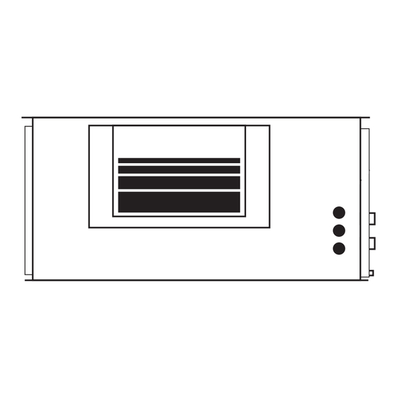
IMD 95Y, 135Y, 170Y, 210Y, 280Y
Ducted
Fan Coil Unit
Dimensions (mm)
Not to Scale
Fig. 1
IMD 95Y
SPRING MTG CTRS
HANGING CENTRES
85
595
OPTIONAL
SPRING MTG
CENTRES
530
HANGING
CENTRES
145
400
MOTOR DRIVER
ACCESS PANEL
360 OA
770
OVERALL
Fig. 2 IMD 135Y, 170Y
SPRING MTG CTRS
HANGING CENTRES
85
595
OPTIONAL
SPRING MTG
CENTRES
530
HANGING
CENTRES
B
MOTOR DRIVER
ACCESS PANEL
360 OA
690
650
OPTIONAL
590
FILTER BOX WITH
FILTER ACCESS
EACH SIDE
WATER
CONNECTIONS:
25 BSP MALE
(HEATING
15 BSP MALE)
MOUNTING
SLOTS 20 x 9
ELECTRICAL
CONDUIT HOLES
15
225
120
MODEL
IMD 135
C
IMD 170
D
A
OPTIONAL FILTER BOX
WITH FILTER ACCESS
EACH SIDE
WATER
CONNECTIONS:
25 BSP MALE
(HEATING
15 BSP MALE)
MOUNTING
SLOTS 20 x 9
400
ELECTRICAL
15
CONDUIT HOLES
225
120
E
OVERALL
(c/w EC motor)
PROJECTION
Net Weight 45 kg
(excluding water)
FAN ACCESS VIA
REMOVEABLE BASE
& DRAIN TRAY,
OR VIA TOP PANEL
135
ELECTRICAL
ACCESS PANEL
60
60
15
285
OUT
IN
60
DRAIN 19 OD
630 OA
A
B
C
D
E
765
265
865
825
945
910
340
1015
975
1095
Net Weight
(exclud-
ing water)
IMD 135 45 kg
IMD 170 59 kg
FAN ACCESS VIA
REMOVEABLE BASE
& DRAIN TRAY,
OR VIA TOP PANEL
ELECTRICAL
135
ACCESS PANEL
60
60
15
285
OUT
IN
60
DRAIN 19 OD
630 OA
Installation &
Maintenance
GENERAL
The IMD ducted fan coil units must be
installed in accordance with all national and
local safety codes.
Options
1. Filter Box
2. Spring Mounting Kit
FILTER BOX (Option)
The Filter Box is installed by unscrewing
the return air spigot and replacing it with
the Filter Box's filter-integrated spigot. The
filter may be accessed from either side of
this spigot. This new spigot has a depth of
135 mm, instead of 60 mm.
INSTALLATION
Positioning & Mounting
When determining the position of the fan coil
unit, allow adequate space around the unit
to facilitate water pipe/hose connections,
future servicing and maintenance. Ensure
there is enough working space in front of
the electrical access panel. Allow adequate
clearance for the filter to be withdrawn to
its full length from either end of the unit.
Provision should be made for access to
remove the unit from the ceiling if the need
arises.
If the filter box option is to be used, allow
adequate clearance for the filter to be
withdrawn to its full length.
If low noise is a critical factor in the
installation, refer to Figure 8 for noise
isolation recommendations.
It is recommended that the unit be mounted
using the spring mounting system, supplied
as an optional extra (Fig.5). This system
minimises transfer of vibration into the
building structure.
If a more rigid installation can be tolerated,
then suspend the unit from four threaded
rods (not supplied) and use locknuts (not
supplied), as shown in Figure 6.
The unit has a built-in sloping drain tray,
therefore mount it level.
When finally positioned, tighten the lock
nuts on the mounting rods from above and
below the mounting flange to give a firm
installation (see Fig. 6).
Condensate Drain
The condensate drain should be trapped
outside the unit cabinet. The trap should
have a vertical height of at least 50 mm.
The drain should have a slope of at least
1 in 50 and must not be piped to a level
above the unit drain tray. (Refer Fig.7). Use
flexible tube to connect the unit's drain stub
to the external drain pipe.
For long condensate pipe runs, fit a vent
pipe near the drain trap. The top of the vent
Advertisement

Related Manuals for TemperZone IMD 95Y


Summary of Contents for TemperZone IMD 95Y
- Page 1 IMD 95Y, 135Y, 170Y, 210Y, 280Y (c/w EC motor) Ducted Installation & Fan Coil Unit Maintenance Dimensions (mm) GENERAL PROJECTION The IMD ducted fan coil units must be Not to Scale installed in accordance with all national and local safety codes.
-
Page 2: Condensate Drain
Fig. 3 IMD 210Y pipe must be at least 100 mm above the IMD unit's drain tray. Net Weight 59 kg 1150 (excluding water) It is essential that the drainage system is SPRING MTG CTRS 1110 checked by pouring water in the drain tray HANGING CENTRES OPTIONAL 1065... -
Page 3: Six Monthly
COMMISSIONING Six Monthly NOTE 1. Check that the thermostat is 1. Check condensate drain for free The manufacturer reserves the right to correctly wired and set at the desired drainage. change specifications at any time without temperature. 2. Check heat exchanger coil; vacuum or notice or obligation. - Page 4 IMD 135Y DIP Switch Refer table for settings INPUTS OUTPUT Com L M +V 0V In +V 0V Out...
- Page 5 IMD 95/170/210/280 Y DIP Switch Refer table for settings INPUTS OUTPUT Com L M +V 0V In +V 0V Out © temperzone limited 2022 05/22 Pamphlet No. 3989...
Need help?
Do you have a question about the IMD 95Y and is the answer not in the manual?
Questions and answers