Advertisement
Quick Links
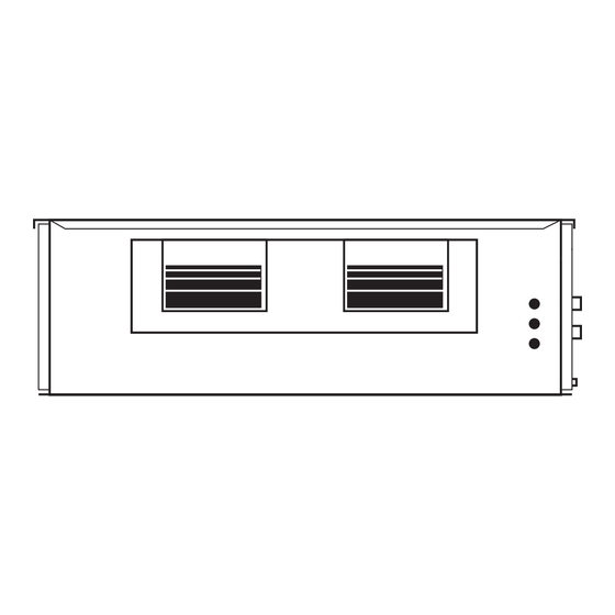
IMD 420Y, 550Y
Ducted
Fan Coil Units
Dimensions (mm)
Not to Scale
Fig. 1
MOUNTING CENTRES
125
W
688
OPTIONAL
SPRING MTG
CENTRES
Z
325
ACCESS
PANEL
B
OVERALL
OVERALL
MODEL
A
B
C
IMD 420
1625
575
975
IMD 550
1680
700
1030
Note: The manufacturer reserves the right to change specifications at any time
without notice or obligation. Certified dimensions available on request.
Fig. 2 Spring Mounting
RECOMMENDED
MOUNTING
SYSTEM
(OPTIONAL
EXTRA)
(c/w EC motor)
PROJECTION
MODEL
IMD 420Y
IMD 550Y
H
OPTIONAL
FILTER BOX WITH
FILTER ACCESS
F
EACH SIDE
WATER CONNECTIONS:
32 BSP MALE
(HEATING 32 BSP MALE)
X
600
MOUNTING
STRAP
CENTRES
Y
C
ELECTRICAL
CONDUIT HOLES
35
D
E
A
D
E
F
G
H
300
240
1375
425
1518
310
355
1430
555
1573
Fig. 3 Strap Mounting
CORNER LOADS (kg)
W
X
Y
Z
35
42
38
30
42
47
37
40
Net Weight
(excluding water)
IMD 420Y 145 kg
IMD 550Y 166 kg
FAN ACCESS VIA
REMOVEABLE BASE
& DRAIN TRAY,
OR VIA TOP PANEL
ELECTRICAL
ACCESS PANEL
150
65
65
75
G
80
DRAIN 28 OD
735 OA
ADJUSTABLE
MOUNTING
STRAPS SUPPLIED
(1 OF 4)
SCREWS
SUPPLIED
Installation &
Maintenance
GENERAL
The IMD ducted fan coil units must be
installed in accordance with all national and
local safety codes.
Options
1. Filter Box
2. Spring Mounting Kit
FILTER BOX (Option)
The Filter Box is installed by unscrewing
the return air spigot and replacing it with
the Filter Box's filter-integrated spigot. The
filter may be accessed from either side of
this spigot. This new spigot has a depth of
150 mm, instead of 65 mm.
INSTALLATION
Positioning & Mounting
Provide 500 mm minimum clearance to both
ends of the unit. If the filter box option is to
be used, allow adequate clearance for the
filter to be withdrawn to its full length.
If low noise is a critical factor in the
installation, refer to Figure 5 for noise
isolation recommendations.
It is recommended that the unit be mounted
using the spring mounting system, supplied
as an optional extra (Fig.2). This system
minimises transfer of vibration into the
building structure.
If a more rigid installation can be tolerated,
then suspend the unit using the four straps
supplied, as shown in Figure 3.
Alternatively, holes are supplied in the
mounting flange for the use of threaded
mounting rods (not supplied).
The unit has a built-in sloping drain tray,
therefore mount it level.
Condensate Drain
The condensate drain should be trapped
outside the unit cabinet. The trap should
have a vertical height of at least 50 mm.
The drain should have a slope of at least
1 in 50 and must not be piped to a level
above the unit drain tray. (Refer Fig.4). Use
flexible tube to connect the unit's drain stub
to the external drain pipe.
For long condensate pipe runs, fit a vent
pipe near the drain trap. The top of the vent
pipe must be at least 100 mm above the
IMD unit's drain tray.
It is essential that the drainage system is
checked by pouring water in the drain tray
and seeing that it discharges at the end of
the drain and does not overflow the drain
tray.
Note: The built-in drain tray can be
removed for cleaning (or fan access) by first
removing the unit's base.
Advertisement

Related Manuals for TemperZone IMD 420Y


Summary of Contents for TemperZone IMD 420Y
- Page 1 IMD 550Y Fig. 1 Options Net Weight 1. Filter Box (excluding water) 2. Spring Mounting Kit IMD 420Y 145 kg OPTIONAL MOUNTING CENTRES IMD 550Y 166 kg FILTER BOX WITH FILTER ACCESS EACH SIDE FILTER BOX (Option)
- Page 2 Fig. 4 ELECTRICAL WIRING Condensate Drain The electrical supply required (including FLEXIBLE voltage fluctuation limits) is: TUBE VENT PIPE 100 mm 1 phase 200-252 V a.c. 50 Hz with neutral 70–100mm FOR LONG APPROX. and earth. The supply to have an isolation CONDENSATE UNIT DRAIN RUNS...
- Page 3 Fig. 5 Application Considerations Recommendations for Noise Isolation - particularly for high static installations: 1. Avoid installing units, with non-ducted return air, directly above spaces where noise is critical. 2. Use flexible connections between unit and rigid ducting. 3. Use generously sized acoustically lined ducts. 4.
- Page 4 DIP Switch Refer table for settings INPUTS OUTPUT Com L M +V 0V In +V 0V Out 05/24 Pamphlet No. 3831 © temperzone limited 2024...
Need help?
Do you have a question about the IMD 420Y and is the answer not in the manual?
Questions and answers