Table of Contents
Advertisement
Quick Links
Advertisement
Table of Contents

Related Manuals for Grundfos UPMS


Summary of Contents for Grundfos UPMS
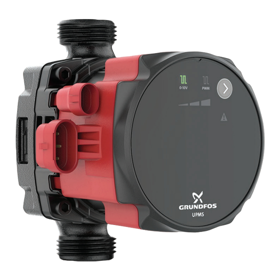
- Page 1 GRUNDFOS INSTRUCTIONS UPMS Installation and operating instructions...
- Page 3 UPMS English (US) Installation and operating instructions ............4...
-
Page 4: Table Of Contents
Identification......6 warranty. Grundfos will not be liable for damage or wear to products Approvals . -
Page 5: General Information
3.1 Product description Installation and operation must comply with local regulations and accepted codes of good practice. 2.1 Hazard statements The symbols and hazard statements below may appear in Grundfos installation and operating instructions, safety instructions and service instructions. DANGER Indicates a hazardous situation which, if not avoided, will result in death or serious personal injury. -
Page 6: Pumped Liquids
If required, 50 % of the volume solution of glycol and water can be pMax: XXX PSI / XXXXX Mpa Enclosure type 2 used. However, a decrease in pump performance may occur due to Grundfos Holding A/S Boitier de type 2 an increase in the viscosity of the solution. Contact the DK-8850 Bjerringbro... -
Page 7: Code Explanation
3.4.2 Type key 4. Receiving the product Example: UPMS 20-58 F 165 115V CB 9H 4.1 Inspecting the product Code Explanation Designation CAUTION UPMS Standard Pump type Crushing of feet R 1/2" / G 1" Minor or moderate personal injury R 3/4"... -
Page 8: Mechanical Installation
‐ A damaged product must be repaired or replaced by 1. Fit the two gaskets supplied, if applicable, with the pump when Grundfos or a service workshop authorized by you mount the pump in the pipe. Grundfos. WARNING Biological hazard Death or serious personal injury ‐... -
Page 9: Changing The Control Box Position
5.2 Changing the control box position CAUTION Hot surface Minor or moderate personal injury ‐ Position the pump so that persons cannot accidentally come into contact with hot surfaces. WARNING Pressurized system Minor or moderate personal injury ‐ Before dismantling the pump, drain the system or close the isolating valves on both sides of the pump. -
Page 10: Electrical Connection
6.1.1 Wiring the pump with conduit box The conduit connector and conduit are not supplied by The power connector can be fitted with AWG 20 - Grundfos. AWG 12 wires. Follow the steps below to wire the pump when equipped with a 2. -
Page 11: Signal-Cable Connection
6.1.3 Wiring diagram 6.2 Signal-cable connection WARNING Electric shock Death or serious personal injury ‐ External signal cables must be in accordance with chapter 725 of the NEC in order to insulate this circuit from others. 6.1.4 Supply voltage 1 × 115V +10 % / -10 %, 60 Hz. Do not connect the signal reference wire to the ground. -
Page 12: Starting Up The Product
7. Starting up the product 7.2 Dry-running protection The dry-running protection protects the pump against dry running • Fill the system with liquid and vent it. during startup and normal operation. • Make sure the required minimum inlet pressure is available at the pump inlet. -
Page 13: Control Functions
Use the button (3) to select 0-10 V or PWM. 8.1.1 Light fields indication Active light fields Description 0-10 V 0-10V UPMS operating panel with external signal 9 o'clock control box position MlllJl 0-10V PWM Setting I Setting II Setting III... -
Page 14: Control Modes
8.2 Control modes Depending on the variant, UPMS can be set to the following control modes: • Constant curve • • 0-10 V. Constant curve can be set to pump setting I, II, III. 8.2.1 Constant curve In the constant-curve mode, the pump runs at a constant curve, which means that it runs at constant speed or power. -
Page 15: Pump Information
Variable speed from min. to max. 10 % < PWM signal ≤ 84 % speed PWM feedback signal, UPMS power consumption 84 % < PWM signal ≤ 91 % Min. speed 91 % < PWM signal ≤ 95 % Hysteresis area: on/off Pos. - Page 16 8.2.4 0-10 VDC Output transistor status indicates pump operation. The output signal is activated in the following cases: The UPMS circulators can be externally speed-controlled by an analog 0-10 VDC signal. • The pump stops when the input signal is between 0.5 and 2 V.
-
Page 17: Setting Of The Product
9. Setting of the product Press the button to select external signal type (if relevant) or constant-curve setting (I, II or III). The LEDs will indicate the control mode. See the table below. Note that the LED for the chosen setting flashes to indicate that it is active. -
Page 18: Service
‐ A damaged product must be repaired or replaced by 3. Loosen the conduit. Grundfos or a service workshop authorized by 4. Lift the orange levers to loosen the wires. Grundfos. 5. Pull the conduit out of the conduit box. -
Page 19: Fault Finding
WARNING Electric shock Death or serious personal injury ‐ A damaged product must be repaired or replaced by Grundfos or a service workshop authorized by Grundfos. WARNING Hot surface Minor or moderate personal injury ‐ The pump housing may be hot due to the pumped liquid being scalding hot. -
Page 20: Dry Running
• Increase the flow. 11.8 Noise in the system Cause Remedy The flow is too high. • Lower the flow. There is air in the system 1. Connect to Grundfos GO 2. choose Settings 3. Start "Vent pump (15 minutes)". -
Page 21: Technical Data
12. Technical data 12.1 Duty range Max. flow rate, Q Max. head, H [ft (m)] [gpm (m UPMS 15-78 16 (3.7) 25.6 (7.8) UPMS 15-58 13.6 (3.1) 19 (5.8) UPMS 20-58 13.6 (3.1) 19 (5.8) UPMS 20-78 16 (3.6) 25.6 (7.8) UPMS 25-78 16 (3.6) -
Page 22: Miscellaneous Data
This product or parts of it must be disposed of in an environmentally sound way. Click here to submit your feedback 1. Use the public or private waste collection service. 2. If this is not possible, contact the nearest Grundfos company or service workshop. See also end-of-life information at www.grundfos.com/product-... - Page 23 2941 Brighton Road Oakville, Ontario L6H 6C9 Tel.: +1-905 829 9533 Fax: +1-905 829 9512 Mexico Bombas GRUNDFOS de México S.A. de C.V. Boulevard TLC No. 15 Parque industrial Stiva Aeropuerto Apodaca, N.L. 66600 Tel.: +52-81-8144 4000 Fax: +52-81-8144 4010...
- Page 24 92908164 11.2023 ECM: 1360996 www.grundfos.com...
Need help?
Do you have a question about the UPMS and is the answer not in the manual?
Questions and answers