Table of Contents

Related Manuals for Ascendor PLK8


Summary of Contents for Ascendor PLK8
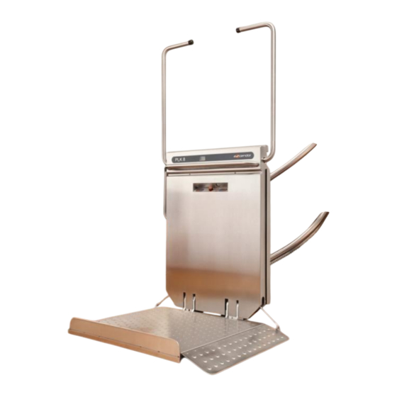
- Page 1 Platform stair lift PLK8 ORIGINAL-user manual Part 2: Assembly Instruction English Version 2.02 ASCENDOR GMBH Drautendorf 48 4174 Niederwaldkirchen Austria Tel.: +43 7231 40040 Fax: +43 7231 40040-590 office@ascendor.com www.ascendor.com...
-
Page 2: Assembly Instruction
Assembly Instruction Platform stair lift PLK8 Date of issue: November 2016 Version 2.02 Part 2 / 3 of the original user manual My ASCENDOR-partner is: Page 2 Version 2.02 Assembly Instruction PLK8... -
Page 3: Table Of Contents
Sample installation drawing ........................15 Test report after finished installation ......................17 The further parts of the original user manual are: • Part 1: Operating Manual • Part 3: Maintenance and Service Manual Assembly Instruction PLK8 Version 2.02 Page 3... -
Page 4: Introduction
1. Introduction This assembly instruction is designed to assist you during the installation of the platform stair lift PLK8. Although the information and photographs printed in this manual illustrate a particular stair lift, the description is still relevant for all other installations. -
Page 5: Additional Information For The Fitters
The travel rail of the stair lift consists of one or more parts which can vary between 1 and 5 meters in length. In case of uncertainty or arising questions, please refer to your Ascendor partner or do not hesitate to call our customer service at +43 (0)7231/40040. -
Page 6: Tools Required For Installation
3. Tools required for installation Ascendor recommends carrying following installation tools with you: • Additional light sources for installation work • Tape measure • Spirit level, short, with digital display • Spirit level, long approx. 1500mm • One-hand bar clamp •... -
Page 7: Attaching The Travel Rails Directly To The Wall
Select the correct fasteners to correspond with the properties of the supporting wall. The fitter must decide on site which materials are appropriate and the fasteners that have to be used. Ascendor accepts no responsibility or liability for this work. The following fasteners are recommended: •... - Page 8 It’s therefore essential that the angle of the travel rails corresponds with the information on the drawing! It’s important to ensure that the mounting brackets between handrail and rack are mounted in a vertical position! Page 8 Version 2.02 Assembly Instruction PLK8...
-
Page 9: Securing The Travel Rail Mounting Brackets
Fix the travel rail on each bracket three times to the wall / stanchion. Use countersunk screws at the upper hole! The middle and lower screws between the handrail and rack are not allowed to protrude more than 20mm from the bracket! Assembly Instruction PLK8 Version 2.02 Page 9... -
Page 10: Attaching The Travel Rails With Stanchions / Posts
The position of the rest of the stanchions is predetermined by the position of the mounting brackets. Please ensure that the threaded holes are drilled in the middle of the stanchion and that the stanchions are in a vertical position! Page 10 Version 2.02 Assembly Instruction PLK8... -
Page 11: Fixation Of Rail Cover Panels
After that attach the panel to the holder, align the panel and fix the 2 part of the holder. Once done fix the remaining panel holders. Ensure that all panels are mounted on the same height, to have a consistent good looking general view. Assembly Instruction PLK8 Version 2.02 Page 11... -
Page 12: Mounting The Platform Stair Lift Onto The Travel Rails
It can be positioned near the upper or lower station. Check the LED of the charger to see whether the batteries are being recharged. An orange LED shows that the batteries are charged at the moment. Page 12 Version 2.02 Assembly Instruction PLK8... -
Page 13: Fitting The Limit Switches
The brass bar can be moved up or down the plastic bracket depending on the required final stopping position. Assembly Instruction PLK8 Version 2.02 Page 13... -
Page 14: Completing The Installation
Wall mounted operating units should be fixed at a height of approx. 90cm, besides there should be enough space (more than 1m) between the wall mounted operating unit and the parked lift • Attach the quick start guide (sticker) • Attach anti-slip tape onto the platform (optionally) Page 14 Version 2.02 Assembly Instruction PLK8... -
Page 15: Sample Installation Drawing
Sample installation drawing Assembly Instruction PLK8 Version 2.02 Page 15... - Page 16 Page 16 Version 2.02 Assembly Instruction PLK8...
-
Page 17: Test Report After Finished Installation
Function control for mechanical parts and software Access ramps open and close completely Safety bars open and close completely Platform open and close completely Check battery charger function __________________________________ ____________________________________ Date, Name Signature Assembly Instruction PLK8 Version 2.02 Page 17...
Need help?
Do you have a question about the PLK8 and is the answer not in the manual?
Questions and answers