Ascendor PLG7 Original User Manual
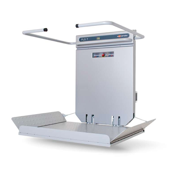
Platform stair lift
Hide thumbs
Also See for PLG7:
- Assembly instruction manual (17 pages) ,
- Original user manual (29 pages)
Table of Contents
Advertisement
Advertisement
Table of Contents

Related Manuals for Ascendor PLG7


Summary of Contents for Ascendor PLG7
- Page 1 Platform stair lift PLG7 / PLK8 ORIGINAL-user manual Part 3: Maintenance and Service Manual Description of PLC Diagnostic System English Version 2.14 ASCENDOR GMBH Drautendorf 48 4174 Niederwaldkirchen Austria Tel.: +43 7231 40040 Fax: +43 7231 40040-590 office@ascendor.com www.ascendor.com...
- Page 2 Maintenance and Service Manual Platform stair lift PLG7 / PLK8 Date of issue: March 2019 Version 2.14 For serial numbers PLG7-07-x / PLK8-07-x Part 3 / 3 of the original user manual My ASCENDOR-Partner is: Page 2 Version 2.14 Maintenance and Service Manual...
-
Page 3: Table Of Contents
Contents Introduction ..............................5 Health and safety regulations .......................... 5 General information ..........................5 Safety precautions before starting service work ..................5 Storage of the lift unit without a battery charge ..................6 Removal of the front plastic cover ........................6 Service schedule .............................. - Page 4 Remove / replace components ......................... 23 12.1 Disassembling the PLG7 safety catcher ....................23 12.2 Reset of the PLK8 safety catcher ......................24 12.3 Testing the PLK8 safety catcher ......................25 12.4 Removing the drive motor and gearbox....................25 12.5 Removing the safety bar motors ......................
-
Page 5: Introduction
1. Introduction The equipment tools described in this Maintenance and Service Manual were those available at the time of writing. Due to the continual development and improvement of our product we reserve the right to alter the contents and technical data without consultation or prior warning. A precondition for the uninterrupted operation of this stair lift, free of any technical problems is the strict compliance with the content of this manual. -
Page 6: Storage Of The Lift Unit Without A Battery Charge
2.3 Storage of the lift unit without a battery charge If the lift is not installed immediately after dispatch, the batteries must be disconnected from the circuit. Please take the lift out of the wooden transport box, then open the platform and remove the front plastic cover (see chapter 3). -
Page 7: Function Control For Safety Equipment
4.3 Function control for safety equipment • Limit switch TOP • Limit switch BOTTOM • Pressure sensitive contact panel (platform underside) • Emergency stop button • Switch function test of the access ramps open (travel up / down) • Switch function test of the access ramps closed (travel up / down) •... -
Page 8: Documentation
4.7 Documentation After all previous mentioned checks are finished fill out the service plan. You find the plan at the end of this manual (see chapter 16). You should also write down the current hour counter and power blackout counter on the day of service. To read this information please see chapter 8.3. -
Page 9: Recommended Spare Parts Set
Wireless handheld transmitter XT401467 Holder charging point, extra long XT401547 Cover charging point, extra long XT401516 Brass charging point Brass screw M4x16 for charging point PLG7 KT000436 KT000479 Brass screw M4x30 for charging point PLK8 XT401223 Platform motor KT000081 Safety catcher... -
Page 10: Position And Function Of The Switches B1 To B28
1 – UP button 2 – DOWN button 3 – folding 1 – limit switch top PLG7 2 – limit switch bottom PLG7 3 – limit switch top PLK8 4 – limit switch bottom PLK8 Positioned on the back side of the lift at PLG7 and PLK8 units 1 –... - Page 11 1 – safety catcher PLG7 2 – safety catcher PLK8 Positioned on the back side of the lift at PLG7 and PLK8 units 1 – ramp safety switch top 2 – ramp safety switch bottom 3 – platform switch up (white colour) 4 –...
- Page 12 roll monitoring PLK8 safety catcher 1 – 3 stop 2 – curve speed reducer 1 b25.1 3 – curve speed reducer 2 Positioned on the back side of the lift (only for PLK8 units) 1 – Emergency close platform 2 – Emergency open platform Page 12 Version 2.14 Maintenance and Service Manual...
-
Page 13: Trouble Shooting Guide
6. Trouble shooting guide Maintenance and Service Manual Version 2.14 Page 13... - Page 14 Page 14 Version 2.14 Maintenance and Service Manual...
-
Page 15: Failure Code Motor Controller
7. Failure code motor controller When a problem concerning the motor controller occurs, a blink code (0 or 1) will also be visible on the Ready- LED on the main circuit board. MOTORCONTR OK (green) In addition a LED MOTORCONTR OK will be visible on the printed circuit board indicating errors by a flash code. -
Page 16: Description Of The Plc Diagnostic System
After you have opened the main menu the Input-Output picture appears. This is very useful for failure search. In the course of trouble shooting with Ascendor telephone support you may be asked to handover this information. (I = Input, O = Output) -
Page 17: Plc Inputs
8.2.1 PLC Inputs I-1 UP button I-A upper safety bar down I-2 DOWN button I-B lower safety bar down I-3 limit switch TOP I-C 3 stop I-4 limit switch BOTTOM I-D charging, weight control equipment I-5 platform switch I-E internal control I-6 emergency stop circuit I-F current measurement I-7 motor ON... -
Page 18: Onboard Control
8.4 Onboard control Onboard controls prior: 0 = Onboard and remote control are coequal 1 = Onboard control has priority Once this function is activated the UP and DOWN buttons on the remote controls are only functional when the platform is folded! 8.5 Monitoring of platform motor Maximal current value (max.): Protects the platform and safety bar motors from electrical... -
Page 19: Fuses
9. Fuses The fuses are located in two positions on the lift; behind the front plastic cover next to the batteries and under the top service hatch cover at the rear of the lift. Push button Platform motor Main Power Connection cable for Platform OPEN Fuse F2 - 7,5A... -
Page 20: Adjusting Settings
Adjusting settings 11.1 Adjusting the platform The pitch angle of the platform can be adjusted with the sheet metal plates. These are located on the bottom of the aluminium profiles. Turn the reverse plates 180 degrees for raising the platform height. ! A T T E N T I O N ! Adjust the switch b20 (platform horizontal) if necessary! 11.2 Setting the safety bar slip clutch... -
Page 21: Adjusting Of The Access Ramps
11.4 Adjusting of the access ramps The angle of the access ramp can be adjusted with the threaded rod. Threaded rod The angle can also be adjusted with the Bowden cable. Lengthen the cable for flatter angle. Shorten the cable for steeper angle. 11.5 Memorising remote controls Remove the front plastic cover. - Page 22 By shortly pushing the brown button (0.5 sec.) on the radio receiver the LED begins to flash for approximately 4 seconds. Button Press now within this 4 seconds the UP or DOWN button on the remote control (handheld or wall mounted).
-
Page 23: Remove / Replace Components
Remove / replace components 12.1 Disassembling the PLG7 safety catcher After triggering the safety catcher, the lift can be moved by using the emergency drive function. Try to find a suitable position to remove the safety catcher. Remove the front plastic cover (see chapter 3) and press down the terminal to release the O and P cable on the X1 terminal block, located on the main printed circuit board. -
Page 24: Reset Of The Plk8 Safety Catcher
12.2 Reset of the PLK8 safety catcher The triggered safety catcher can be reset by using an open ended wrench. Push the spring-pressured lever with the aid of an open ended wrench downwards. Manipulate the levers in the shown order: Tensions lever no. -
Page 25: Testing The Plk8 Safety Catcher
12.3 Testing the PLK8 safety catcher To check the function of the safety catcher pull down the spring tensioned lever no. 1 with an open ended wrench. Pull lever no. 2 away to release spring tension so that the safety catcher triggers. Make now sure that the lever no. -
Page 26: Removing The Safety Bar Motors
12.5 Removing the safety bar motors For PLG7 units: remove the rear plastic cover and remove the radio receiver. For PLK8 units: remove the front plastic cover (see chapter 3) and remove the radio receiver. Ensure that the safety bars are in the horizontal position. -
Page 27: Instruction For The Transfer Of A New Plc Program
Instruction for the transfer of a new PLC program With the aid of a memory card a new PLC program can be imported to the PLC. • position the lift to a station • remove the front plastic cover (see chapter 3) •... -
Page 28: Wiring Diagram Main Circuit Board
Wiring diagram main circuit board Page 28 Version 2.14 Maintenance and Service Manual... - Page 29 Bottom terminal block at main circuit board (gray): UP button Outputs: O1 disengage motor control Inputs: DOWN button O2 relay platform motor limit switch TOP O3 safety bar motor top O4 safety bar motor down limit switch BOTTOM platform switch O5 reverse polarity relay K1 O6 moving magnet emergency stop circuit...
-
Page 30: Leds On Main Circuit Board
14.1 LEDs on main circuit board shines when UP command is applied DOWN shines when DOWN command is applied EMERGENCY shines when emergency stop is OK (not activated) OVERSPEED shines when emergency stop and safety catcher are OK (not activated) UP/DOWN SAFETY shines when directional UP/DOWN safety circuit is OK (access ramp, contact strip, contact-tray) / only during active movement command... -
Page 31: Wiring Diagram
Wiring diagram Maintenance and Service Manual Version 2.14 Page 31... - Page 32 Page 32 Version 2.14 Maintenance and Service Manual...
- Page 33 Maintenance and Service Manual Version 2.14 Page 33...
- Page 34 Page 34 Version 2.14 Maintenance and Service Manual...
- Page 35 Maintenance and Service Manual Version 2.14 Page 35...
- Page 36 Page 36 Version 2.14 Maintenance and Service Manual...
- Page 37 Maintenance and Service Manual Version 2.14 Page 37...
- Page 38 Page 38 Version 2.14 Maintenance and Service Manual...
- Page 39 Maintenance and Service Manual Version 2.14 Page 39...
- Page 40 Page 40 Version 2.14 Maintenance and Service Manual...
- Page 41 Maintenance and Service Manual Version 2.14 Page 41...
- Page 42 Page 42 Version 2.14 Maintenance and Service Manual...
-
Page 43: Service Plan
Service plan Maintenance and Service Manual Version 2.14 Page 43... - Page 44 Page 44 Version 2.14 Maintenance and Service Manual...
Need help?
Do you have a question about the PLG7 and is the answer not in the manual?
Questions and answers