
Related Manuals for Bosch HighFlow 6000


Summary of Contents for Bosch HighFlow 6000
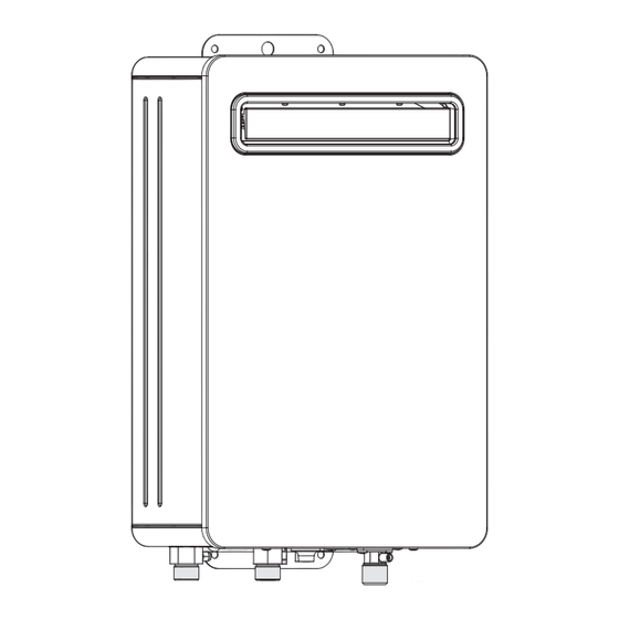
- Page 1 Installation Manual Gas continuous flow water heaters HighFlow 6000 GWH16/20/26 3 CT E23/31 F6 L S2405 6720817545-00.1V...
-
Page 2: Table Of Contents
5.1 Factory settings ......15 5.2 Service function ......16 HighFlow 6000 – 6 721 803 792 (2019/04) -
Page 3: Explanation Of Symbols And Safety Instructions
▶ Ensure that only personnel who can operate this appliance – a list entry (second level) correctly have access to it. Table 1 ▶ Refer to the operating and user instructions before adjusting the water heater. HighFlow 6000 – 6 721 803 792 (2019/04) -
Page 4: Installation
(700 kPa), between the water out. heater and the pressure limiting valve. ▶ Failure to comply with this requirement may void the warranty. ▶ Refer to AS/NZS5601 for the relevant gas pipe sizing. HighFlow 6000 – 6 721 803 792 (2019/04) -
Page 5: Product Details
Electrical connection: 230/240 V, 50 Hz Model overview Optional accessories • Main remote control • Bathroom remote control • Recess Box • Flue diverters Table 3 [GWH] Gas continuous flow water heater HighFlow 6000 – 6 721 803 792 (2019/04) -
Page 6: Dimensions And Minimum Clearances
Product details Dimensions and minimum clearances >10 >10 6720817545-02.1V Fig. 1 Dimensions (in mm) Connections Water Cold Nat. GWH16/20/26 ¾ “ ¾ “ ¾ “ ¾ “ Table 4 HighFlow 6000 – 6 721 803 792 (2019/04) -
Page 7: Appliance Layout
[8] Hot water outlet [9] Cold water inlet [10] By-pass valve [11] Gas inlet [12] Electronic control unit [13] Gas valve [14] Gas pressure test point [15] Ignition electrode [16] Heat exchanger HighFlow 6000 – 6 721 803 792 (2019/04) -
Page 8: Electrical Wiring Diagram
[6] Connection for remote control (optional) [7] By-pass valve [8] Modulation electrovalve (gas) [9] Segmentation electrovalve 1 (gas) [10] Segmentation electrovalve 2 (gas) [11] Safety electrovalve (gas) [12] Thermal fuse [13] Water flow sensor HighFlow 6000 – 6 721 803 792 (2019/04) -
Page 9: Specification
▶ Always shut off the gas valve before carrying out work on tempering valve be fitted as per AS3498. gas pipes. This appliance must not be installed indoors or in an enclosed space as per AS/NZS5601. HighFlow 6000 – 6 721 803 792 (2019/04) -
Page 10: Choice Of Installation Site
They may be found in solvents, paints, adhesives, aerosol propellants and household cleaners.If these conditions cannot be guaranteed, a different site must be chosen for the appliance. HighFlow 6000 – 6 721 803 792 (2019/04) -
Page 11: Minimum Clearances
E From an electricity meter or fuse box (P) F From a drain pipe or soil pipe G Horizontally from any building structure Packaging materials can be recycled. obstruction facing a terminal HighFlow 6000 – 6 721 803 792 (2019/04) -
Page 12: Water Connection
▶ Install a pressure reducing valve if required. It's preferable to install this valve close to the water meter. ▶ Press the button to select the altitude of the installation site according to Table 7. HighFlow 6000 – 6 721 803 792 (2019/04) -
Page 13: Remote Control Connection (Optional)
[3] Communication cable Connecting the communication cable to the appliance ▶ Unscrew the electronic control unit fixing screw. ▶ Remove the grommet and feed the remote control communication cable through it. HighFlow 6000 – 6 721 803 792 (2019/04) -
Page 14: Connecting The Power Cable
▶ Close all hot water taps. ▶ Reset the appliance by switching it off at the socket and unplugging the cord. If the power cable is damaged, it must be replaced with a Bosch supplied spare part. 4.10 Bluetooth instruction Bosch have developed Bosch Water and Bosch ProWater apps ▶... -
Page 15: Changing The Setpoint Limit Temperature (Only For 55 °C Preset Appliances)
DANGER: required. The setpoint can be adjusted between -2.5 °C and +2.5 °C. ▶ The operations described below must only be carried out by an authorised technician. HighFlow 6000 – 6 721 803 792 (2019/04) -
Page 16: Service Function
▶ Press the button ▶ Open a hot water tap. Fig. 11 The appliance is now ready for adjustment of the minimum [A] Air pressure test point gas flow. [B] Gas pressure test point HighFlow 6000 – 6 721 803 792 (2019/04) -
Page 17: Adjusting Pressure At The Burner
0.04 - 0.06 Factory default settings are now restored. essure ofthe GWH20 0.03 - 0.05 0.05 - 0.07 burnerMIN GWH26 0.02 - 0.05 0.03 - 0.06 (kPa) -P2 Table 10 Pressure of the burner HighFlow 6000 – 6 721 803 792 (2019/04) -
Page 18: Maintenance
▶ If the soot is not removed, use a stiff brush to carefully clean the fins. ▶ Regions with average/high water hardness: descale the inside of the heat exchanger and the connection pipes by using a diluted solution of hydrochloric acid or white vinegar. HighFlow 6000 – 6 721 803 792 (2019/04) -
Page 19: Start-Up After Completion Of Maintenance
▶ Re-tighten all of the connections. ▶ Check the burner pressure. ▶ Check air tightness of the flue circuit with the front cover fitted. ▶ Check that there are no gas or water leaks. HighFlow 6000 – 6 721 803 792 (2019/04) -
Page 20: Troubleshooting
Loss of ionization in less than 5 ▶ Unplug the electrical connection for 10 seconds. seconds during 5 times. ▶ Reconnect and restart the appliance. ▶ If the problem persists, call an authorised service technician. HighFlow 6000 – 6 721 803 792 (2019/04) -
Page 21: Environment Considerations
NZ 0800 54 33 52. Water quality Environment considerations All Bosch water heating appliances are constructed from high Environmental protection is a fundamental corporate strategy quality materials and components and all are certified for of the Bosch Group. -
Page 22: Warranty Details
1. Warranty NOTE: Any service call costs incurred by the owner or user of Bosch offers, at its option, to repair or exchange this Bosch hot the hot water unit for any matter not covered by the terms of water unit or the relevant part listed in clause 2 below at no... - Page 23 (b) All warranty service calls must conducted by an authorised Bosch service agent. (c) Invoices for attendance and repair of a hot water unit by third parties not authorised by Bosch will not be accepted for payment by Bosch. 6. Privacy Act 1988 (Cth)
- Page 24 Robert Bosch (Australia) Pty Ltd Thermotechnology Division 1555 Centre Road Clayton Victoria 3168 Australia Phone: 1300 30 70 37 Fax: 1300 30 70 38 www.bosch-climate.com.au New Zealand Phone: 0800 54 33 52 Fax: 0800 54 33 55 www.bosch-climate.co.nz...
Need help?
Do you have a question about the HighFlow 6000 and is the answer not in the manual?
Questions and answers