Table of Contents
Advertisement
Advertisement
Table of Contents

Related Manuals for Bosch Compress 3000


Summary of Contents for Bosch Compress 3000
- Page 1 HP 200-1 E AI-F Compress 3000 Electric Heat Pump Water Heater 6720646804-00.1V...
-
Page 2: Table Of Contents
Index Index Warnings Troubleshooting/Problem Solving Appliance details Electrical diagram Overview Features and safety devices Interior components and parts list Specification tables Principle of Operation (brief overview of modes) Protecting the environment Dimensions Limited Warranty Installation instructions Tools required Location requirements Venting (specifications and vent runs) Water piping Electric requirements... -
Page 3: Warnings
Warnings Warnings For your safety Warning: Precautions must be taken Do not store or use gasoline or other flammable, prior to manually operating the relief combustible or corrosive vapors and liquids in the valve to avoid contact with hot water vicinity of this or any other appliance. - Page 4 Warnings For installation in the state of California California Law requires that residential water heaters must be braced, anchored or strapped to resist falling or horizontal displacement due to earthquake motions. For residential water heaters up to 52 gallon capacity, a brochure with generic earthquake bracing instructions can be obtained from: Office of the State Architect, 400 P Street,...
-
Page 5: Appliance Details
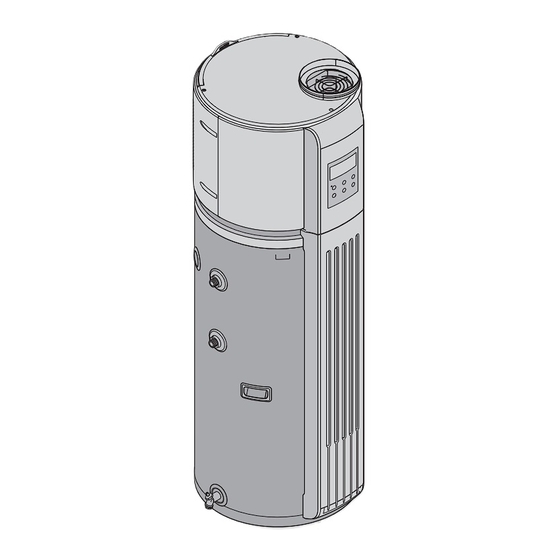
Appliance details Appliance details Overview 6720646804-04.1V Fig. 2 Appliance overview Temperature & pressure relief valve air exchanger, heat may be taken from a mechanical Hot outlet room or a sun porch or attic space, or from hot areas in Cold intlet any other domestic environments. - Page 6 Appliance details Temperature limiting controls (TCOs) The water heater is equipped with two temperature-lim- iting controls (TCOs) that are located above the upper heating heating element in contact with the tank sur- face. If for any reason the water temperature becomes excessively high, the temperature-limiting control (TCO) breaks the power circuit to the heating element.
-
Page 7: Appliance Details 5
Appliance details Specification tables Model HP200-1E... Running models Economy Auto E-heater Running ambient temp. °F 45 - 115 45 - 115 -5 - 130 Outwater Temp. °F Default 120°,100°F - 140°F Power supply Ph/V/Hz 1-240-60 Storage size US Gal Capacity kW / BTU/h 1.50 / 5123 1.50 / 5123... -
Page 8: Principle Of Operation (Brief Overview Of Modes)
Appliance details Principle of Operation (brief overview of modes) 6720646804-01.1V Fig. 3 Air Heat Exchanger Compressor Built in controls offer a variety of operational modes to Cooled / Dehumidified Air suit every user’s needs. When operating with the heat Upper/Lower Electric element pump only (Economic Mode), the water is heated using Condensor Coil (heat exchanger) Drain valve... -
Page 9: Dimensions
Appliance details Dimensions 22.4 6720646804-03.1V Fig. 4 Dimensions (inches) 6 720 646 804... -
Page 10: Installation Instructions
Installation instructions Installation instructions Warning: This water heater SHOULD NOT be installed in a space where The manufacturer’s warranty does not cover any liquids which give off flammable vapors damage or defect caused by improper installation, are to be used or stored. Such liquids attachment or use of any type of energy-saving or other include gasoline, LP gas (butane and unapproved devices (other than those authorized by the... -
Page 11: Venting (Specifications And Vent Runs)
Installation instructions Water piping 3.4.1 Inlet - Outlet connections Refer to the illustration below for suggested typical installation. The installation of unions or flexible copper 5 ” ½ 5 ” ½ connectors is recommended on the hot and cold water connections so that the water heater may be easily dis- connected for servicing if necessary. - Page 12 Installation instructions Failing to install this accessory will void the tank the outlet of the valve and must pitch downward from warranty. the valve to allow complete drainage (by gravity) of the relief valve and discharge line. The end of the discharge 3.4.3 Condensate Drain Tubes line should not be threaded or concealed and should be...
-
Page 13: Electric Requirements
Installation instructions of the relief valve, and possibly the heater itself. Replacing the relief valve will not correct the problem! The suggested method of controlling thermal expansion is to install an expansion tank in the cold water line between the water heater and the check valve. The expansion tank is designed with an air cushion built in that compresses as the system pressure increases, thereby relieving the over-pressure condition and... -
Page 14: Installation Configurations
Installation instructions Installation configurations 3.6.1 Using heat from existing space (Fig. 11) The water heater can remove heat from an area such as a garage or boiler room making the temperature in the space more tolerable in the summer months. 6720646804-13.1V Fig. - Page 15 Installation instructions Note: Pitch horizontal section downward towards termination 1/4" per foot to avoid damage from rain. Note: vent termination may be screened with a minimum 1/4" mesh or larger. 6720646804-12.1V Fig. 13 6 720 646 804...
-
Page 16: Insulation Blanket
4. Ensure that the Temperature and Pressure- below, you should consider treating or conditioning the Relief Valve is operational and the drain line is water entering the water heater. Bosch's warranty does installed per local code. not cover product failures resulting from water quality related issues. -
Page 17: 3.10 What To Expect For "Normal Startup
Installation instructions 3.10 What to expect for “normal startup” After the unit has been installed, with all electrical and water connections secure and checked, the unit should be filled with water (vent tank by opening a hot water faucet somewhere in home to allow tank to fully fill with water). Once tank is full and power is ON, the user must press the POWER button on the user interface. -
Page 18: Operating Instructions
Operating Instructions Operating Instructions Control Pad MODE ENTER press 3 seconds vacation for unlock 6720646804-02.1V Fig. 14 1 Display 4.1.1 Detailed description on the control func- tion 2 Up Auto lock function Use up arrow to increase value or turn page up. If no buttons are pressed 1 minute, the control pad will 3 Running light be locked. - Page 19 Operating Instructions 4.1.2 Description of LCD display AUTO SET TEMP ELEC. 6720646804-15.2V Fig. 15 1 Peak load shifting mode 1 Note: when the unit is on auto mode this icon will flash slowly. Under this mode will be illuminated. Heat pump mode will run and users can set water temperature.
-
Page 20: Safety Warnings
Operating Instructions Safety warnings Water temperature setting The temperature of the water in the water heater can be Warning: Hydrogen gas can be regulated by adjusting the temperature setting up or produced in a hot water system served down using arrow keys on the control panel. by this water heater that has not been Safety and energy conservation are factors to be con- used for a long period of time (generally... -
Page 21: Operating Modes
Operating Instructions heating one day before your return, so that hot water will be available. For example if you will be gone 14 days, press the VACATION OR AWAY button, press the UP arrow button until the display reads 14 days (the default is 14 days) and press ENTER. -
Page 22: Reset The Temperature Limiting Control
Operating Instructions Reset the temperature limiting control B Turn off power to the water heater. B Pull off front cover below control pad (secured with magnet). Remove upper jacket access panel (Fig. 8) and insulation to access both temperature limiter resets and insulation. -
Page 23: Maintenance And Repair
Maintenance and repair Maintenance and repair Temperature and pressure relief Warning: Internal components of the valve heater can become extremely hot during operation. Use caution when Danger: Before manually operating servicing and removing the front and the relief valve, make certain no one will rear covers. -
Page 24: Vacation And Extended Shutdown
Maintenance and repair The decorative front cover must be removed to access the valve. In order to drain the water heater completely: B Turn off the cold water supply. B Open a hot water faucet or lift the handle on the relief valve to admit air to the tank. -
Page 25: Anode Rod Servicing
Maintenance and repair B Periodically inspect the drain lines and clear any debris that may have collected in the lines. B See Installation Instructions for more information. Anode Rod servicing A water heater anode rod is the most important safety guard any storage tank has against corrosion and pre- mature failure. - Page 26 Troubleshooting/Problem Solving Troubleshooting/Problem Solving NOTE: if the power for the water heater is turned off and then back on, the compres- sor will not start for 3 minutes to avoid in- ternal damage. Problem Cause Solutions Water heater is noisy. Fans are used to move air through Some amount of fan noise is normal (sim- the system.
- Page 27 Troubleshooting/Problem Solving Problem Cause Solutions Not enough or no hot water. Water usage may have exceeded Wait for the water heater to recover after the capacity of the water heater. an abnormal demand. A fuse is blown or a circuit Replace fuse or reset circuit breaker.
- Page 28 Troubleshooting/Problem Solving Error code Meaning Solutions T2 sensor malfunction 1. Check wires for damage. 2. Check T2 sensor. Check wire connections from sensor to control board. 3. Check T2 whether interfere with strong mag- netic field. 4. Check actual temp. whether in O°C - 60°C (tolerance +5°C).
- Page 29 Troubleshooting/Problem Solving Error code Meaning Solutions T5 sensor malfunction 1. Check wires for damage. Measure resistance from control board connection. Refer to ther- mister table 7 2. Check wire connections from sensor to con- trol board. 3. Check T5 sensor for damage. 4.
- Page 30 Troubleshooting/Problem Solving Error code Meaning Solutions Upper Element has no current 1. Check power voltage whether in normal work- ing range. 2. Check wire connections. 3. Check temperature limiters (TCOs). 4. Check upper heating element for damage. 5. Check the wire whether through current sensor in PCB.
- Page 31 Troubleshooting/Problem Solving °C KOhm °C KOhm 336.00 1.070 242.70 0.915 177.00 0.787 130.40 0.680 97.06 0.592 72.94 0.517 55.32 0.450 42.32 0.390 32.65 0.340 25.40 0.300 19.90 0.265 15.71 0.235 12.49 0.209 10.00 0.185 8.06 0.162 6.53 0.145 5.33 0.130 4.37 0.118 3.60...
- Page 32 Troubleshooting/Problem Solving °C KOhm °C KOhm °C KOhm °C KOhm 542.7 68.66 13.59 3.702 511.9 65.62 13.11 3.595 483.0 62.73 12.65 3.492 455.9 59.98 12.21 3.392 430.5 57.37 11.79 3.296 405.7 54.89 11.38 3.203 384.3 52.53 10.99 3.113 363.3 50.28 10.61 3.025 343.6...
- Page 33 Electrical diagram Electrical diagram 6720646804-17.1V Fig. 21 6 720 646 804...
- Page 34 Interior components and parts list Interior components and parts list Fig. 22 6 720 646 804...
- Page 35 Interior components and parts list Code Comp. description 8 738 721 051 0 Screen cover 8 738 721 052 0 Membrane 8 738 721 053 0 Back volute cover 8 738 721 054 0 Front shroud 8 738 721 055 0 Centrifugal fan assembly 8 738 721 060 0 Fan motor...
- Page 36 Protecting the environment Protecting the environment Packing The packing box may be fully recycled as confirmed by the recycling symbol Components Many parts in the heater can be fully recycled in the end of the product life. Contact your city authorities for information about the disposal of recyclable products.
- Page 37 Water Heater is incorporated part of Water Heater has a defect in workmanship or that are not Bosch products are not covered by this materials, BTC, at its option, will repair or replace, warranty and are limited to the warranty of the manu- including labor charges at BTC approved rates, the facturer of such components.
- Page 38 Water Heater. If this action is not possible or you don't receive a response, contact Bosch Thermotechnology Corp., 50 Wentworth Ave- nue, Londonderry, NH 03053. To process your claim, you will need a copy of your original invoice or other proof of purchase and documentation showing the orig- inal installation date and location.
- Page 39 Limited Warranty 6 720 646 804...
- Page 40 Replacement Parts available from: BOSCH THERMOTECHNOLOGY CORP. 50 Wentworth Avenue Londonderry, NH 03053 USA Tel. 866-330-2730 www.boschpro.com © 2011 Bosch Thermotechnology Corp., Londonderry, NH...
Need help?
Do you have a question about the Compress 3000 and is the answer not in the manual?
Questions and answers