
Subscribe to Our Youtube Channel
Related Manuals for Western Co W-HPS-3000DL


Summary of Contents for Western Co W-HPS-3000DL
- Page 1 Serie W-HPS-3000DL~6500D/ W-HPS-3000L~6500 Grid-tied Solar Inverters USER MANUAL V2.00...
-
Page 2: Table Of Contents
CONTENTS SYMBOLS ON THE LABEL ....................3 SAFETY AND WARNINGS ....................4 UNPACKING ......................... 5 3.1 Scope of Delivery ......................5 3.2 Product Overview ......................5 INSTALLING .......................... 7 4.1 Installation Requirement ....................7 4.2 Mounting Location ......................8 4.3 Mounting ........................... 9 4.4 Installing the PE cable ...................... -
Page 3: Symbols On The Label
AVOID DAMP AND AVOID CONTACT MOISTURE HIGH TEMPERATURE SHIPMENT STACK AVOID CONTACT LIMIT: 8 DO NOT DISPOSE WITH CE MARKS HOUSEHOLD WASTE PROCEED OPERATIONS AFTER 5 BREAKABLE ITEM MINUTES DISCHARGE PLACE UPWARDS USER MANUAL IN PACK W-HPS-3000DL~6500D/ W-HPS-3000L~6500 USER MANUAL 3... -
Page 4: Safety And Warnings
2. SAFETY AND WARNINGS All persons who are responsible for mounting, installation, commissioning, maintenance, tests, and service of WESTERN CO inverter products must be suitably trained and qualified for corresponding operations. They MUST be experienced and have knowledge of operation safety and professional methods. -
Page 5: Unpacking
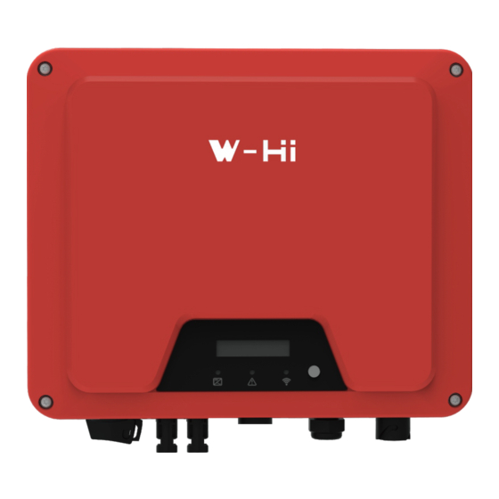
(SEALED) CONNECTOR 1 pair 3.2 Product Overview The total size of W-HPS-3000DL~6500D/ W-HPS-3000L~6500 is 395(width) Ñ328(height) Ñ154(depth) mm. It has 2 pairs of PV input terminals and 2 communication ports. W-HPS-3000DL~6500D has a LCD&LED (W-HPS-3000L~6500 has just LED, determined by user) for getting information and setting parameters at field. - Page 6 For switch on/off the inverter PV Terminal (s) Connected with PV Panel COM1: Wi- Alternative distant communication Fi/RS485/GPRS method COM2: METER/DRED For smart-meter or DRED AC Terminal Connected with AC Grid Secondary PE Terminal For Grounding Protection W-HPS-3000DL~6500D/ W-HPS-3000L~6500 USER MANUAL 6...
-
Page 7: Installing
DO NOT cover the inverter NOR place any objects on top of the inverter. To ensure sufficient room for heat dissipation and maintenance, the clearing space between inverter(s) and other surroundings is indicated below for reference: W-HPS-3000DL~6500D/ W-HPS-3000L~6500 USER MANUAL 7... -
Page 8: Mounting Location
DO NOT mount the inverter on a horizontal surface. 6. For easy installation and operation, please mount the inverter on a height that the display could match eye level. The bottom side where all commissioning terminals are equipped MUST always point downwards. W-HPS-3000DL~6500D/ W-HPS-3000L~6500 USER MANUAL 8... -
Page 9: Mounting
4.4 Installing the PE cable Insert the grounding conductor into the suitable terminal lug and crimp the contact. Thread the M5 * 13 screw through the terminal lug. Tighten it firmly into the housing (screwdriver type: T25, torque: 2.5Nm). W-HPS-3000DL~6500D/ W-HPS-3000L~6500 USER MANUAL 9... -
Page 10: Cable Specification
Information on grounding components: Object Description Housing M5 terminal lug with protective conductor M5Ñ13 pan head screw PE Conductor cross-section: 6mm¬ 4.5 Cable Specification W-HPS-3000DL~6500D/ W-HPS-3000L~6500 USER MANUAL 10... -
Page 11: Commissioning
Please install an individual 2-stage miniature circuit breaker according to the following specifications. Maximum output AC Breaker Rated Model current(A) current(A) W-HPS-3000DL/ W-HPS-3000L W-HPS-3680D/ W-HPS-3680 W-HPS-4000D/ W-HPS-4000 W-HPS-5000D/ W-HPS-5000 W-HPS-6000D/ W-HPS-6000D 27.3 W-HPS-6500D/ W-HPS-6500 29.6 W-HPS-3000DL~6500D/ W-HPS-3000L~6500 USER MANUAL 11... -
Page 12: Dc Wire Assembly And Connection
This product is equipped with residual current protection device internally, in accordance with IEC 60364-7-712. An external residual current protection device is not needed. If the local regulation demands otherwise, it is recommended to install a 30mA Type B residual current protection device. W-HPS-3000DL~6500D/ W-HPS-3000L~6500 USER MANUAL 12... -
Page 13: Communication
Wi-Fi Stick in and tighten. For user guidance and configuration of Wi-Fi Stick, please refer to the corresponding Wi-Fi Stick Guide manual, which is available in printed form inside Documents pack, or on Western CO. website at www.western.it/en 6.1.2 Smart Meter/DRED Connection... -
Page 14: Output Power Control Via Smart Meter
The inverter can control active power output via connecting smart meter, following is the system connection mode. Smart meter as above SDM230-Modbus connecting method and setting baud rate method for Modbus please refer to its user manual. W-HPS-3000DL~6500D/ W-HPS-3000L~6500 USER MANUAL 14... -
Page 15: Auto Test (Only For Italian Market)
CEI 0-21 requirement, Then the next test starts. Test order is 81>.S1(maximum over frequency), 81>.S2(maximum over frequency), 81<.S1(minimum under frequency), 81<.S2(minimum under frequency), 59.S1(maximum voltage over 10min), 59.S2(maximum over voltage), 27.S1(minimum under voltage), 27.S2(minimum under voltage). W-HPS-3000DL~6500D/ W-HPS-3000L~6500 USER MANUAL 15... -
Page 16: Start Up And Operation
>1MOhm using a multimeter. After all installation and checks, close the AC circuit-breaker, then the DC switch. The inverter will start to operate when DC input voltage and grid conditions meet the requirements of inverter startup. W-HPS-3000DL~6500D/ W-HPS-3000L~6500 USER MANUAL 16... -
Page 17: Inverter Led Indicators
7.2 Inverter LED Indicators When the inverter operates, LED symbols on display have the following meanings: W-HPS-3000DL~6500D/ W-HPS-3000L~6500 USER MANUAL 17... -
Page 18: Display And Control Logics
2S Set Language Language Select Pac=xxxxxW English long press 2S short press long press 2S Set Modbus Addr Modbus Addr: Pac=xxxxxW long press 2S short press Ver:V1.0.0.00 Pac=xxxxxW short press Serial Number Pac=xxxxxW short press W-HPS-3000DL~6500D/ W-HPS-3000L~6500 USER MANUAL 18... -
Page 19: Disconnecting From Voltage Sources
Danger to life due to high voltages. Inverter capacitors need 5 minutes to be completely de-energized. When an error occurs, DO NOT remove the cover of the inverter onsite. Improper operations and attempts may induce electric shock. W-HPS-3000DL~6500D/ W-HPS-3000L~6500 USER MANUAL 19... -
Page 20: Technical Parameters
5000 6000 6500 Max. apparent AC power 3300 3680 4400 5000 6000 6600 (VA) Rated grid voltage (Vac) 220/230/240 Rated power frequency 50/60 (Hz) Max. output current (A) 27.3 29.6 Max. output overcurrent protection (A) W-HPS-3000DL~6500D/ W-HPS-3000L~6500 USER MANUAL 20... - Page 21 Residual Current Integrated Monitoring Unit Output Over Current Integrated Protection Output Short Protection Integrated Output Over Voltage Integrated Protection GENERAL DATA Dimensions(W*H*D) mm 395*328*154 Weight (kg) Noise emission(typical) <20 dB(A) User Interface LCD&LED or LED W-HPS-3000DL~6500D/ W-HPS-3000L~6500 USER MANUAL 21...
- Page 22 Default operation per AS/NZS modes 4777.2:2015 Volt-watt response mode Default: Enabled Volt-var response mode Default: Disabled Fixed power factor mode Default: Disabled Reactive power mode Default: Disabled Characteristic power factor Default: Disabled curve for cos φ (P) W-HPS-3000DL~6500D/ W-HPS-3000L~6500 USER MANUAL 22...
-
Page 23: Trouble Shooting
10V. 3. Disconnect the inverter from the utility grid and the PV array, and reconnect it after LED turns off. W-HPS-3000DL~6500D/ W-HPS-3000L~6500 USER MANUAL 23... - Page 24 ⒉If it cannot be recovered for a long time, please confirm: ①whether the AC circuit breaker is disconnected ②whether the AC terminal or fuse is in good contact W-HPS-3000DL~6500D/ W-HPS-3000L~6500 USER MANUAL 24...
- Page 25 ⒊If it cannot be recovered for a long time, please confirm: ①whether the AC circuit breaker is disconnected ②whether the AC terminal is in good connection ③whether the power supply line is normal ④ whether the safety regulation settings are normal W-HPS-3000DL~6500D/ W-HPS-3000L~6500 USER MANUAL 25...
- Page 26 Check the connection of DRM device. If the DRM device is DRM S0 Error DRM switch S0 fault connected normally while this fault occurs, please contact the service. W-HPS-3000DL~6500D/ W-HPS-3000L~6500 USER MANUAL 26...
-
Page 27: System Maintenance
Commissioning commissioning especially the parts in contact with metal surfaces Annually OR Half a year Half a year after first Check if the cables are securely grounded Grounding commissioning Annually OR Half a year W-HPS-3000DL~6500D/ W-HPS-3000L~6500 USER MANUAL 27... -
Page 28: Restarts
13. WARRANTY TERMS AND CONDITIONS Period of validity of the warranty and affected products Western CO. S.r.l. offers a ten-year warranty in the event of defects on entire range of W-HPS grid-tied inverters. The default warranty period is 10 years from the date shown on the receipt confirming the purchase of the product and in any case may exceed 63 months from the date of production. - Page 29 Western Support Centre - will automatically invalidate any warranty claim. − Western CO. S.r.l. is not liable for damage caused to the product by transport; the Buyer must ensure that the packaging is adequate and able to protect the product from breakage and impact caused by the transport itself.
- Page 30 − The method of resolving the complaint is at the sole discretion of Western CO. S.r.l. − In case of device out of warranty, Western CO. S.r.l. will issue a repair quote (if possible) by sending it via e-mail to the Customer.
Need help?
Do you have a question about the W-HPS-3000DL and is the answer not in the manual?
Questions and answers