
Related Manuals for Western Co W-HPT-30K Series


Summary of Contents for Western Co W-HPT-30K Series
- Page 1 Serie W-HPT- 30K/33K/36K/40K/50K Inverter solari trifase collegati alla rete MANUALE UTENTE...
-
Page 2: Table Of Contents
CONTENTS SIMBOLI DI SICUREZZA E AVVERTENZE SULL'ETICHETTA ......3 SICUREZZA E AVVERTENZE ................... 4 DISIMBALLAGGIO ......................5 3.1 Fornitura ..........................5 3.2. Panoramica del prodotto ....................5 INSTALLAZIONE ......................... 7 4.1 Requisiti per l'installazione ....................7 4.2 Posizione di montaggio ....................8 4.3 Mounting ........................... -
Page 3: Simboli Di Sicurezza E Avvertenze Sull'etichetta
1. SIMBOLI DI SICUREZZA E AVVERTENZE SULL'ETICHETTA PERICOLO, AVVERTENZA E RICICLABILE E RIUTILIZZABILE ATTENZIONE ALTA TENSIONE EVITARE OGNI UMIDITÀ EVITARE IL CONTATTO ALTA TEMPERATURA LIMITE DI IMPILAMENTO IN EVITARE IL CONTATTO SEDE DI SPEDIZIONE: 7 NON SMALTIRE CON I RIFIUTI MARCATURE CE DOMESTICI PROCEDERE ALLE... -
Page 4: Sicurezza E Avvertenze
2. SICUREZZA E AVVERTENZE Tutte le persone coinvolte nel montaggio, nell'installazione, nella messa in funzione, nella manutenzione, nei test e nell'assistenza dei prodotti inverter WESTERN CO devono essere adeguatamente formate e qualificate per svolgere le relative operazioni. È necessario che abbiano esperienza e conoscenza in materia di sicurezza operativa e metodi professionali. -
Page 5: Disimballaggio
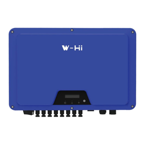
3. DISIMBALLAGGIO 3.1 Fornitura Ispezionare e controllare la completezza della fornitura. Confermare con l'ordine di acquisto. 3.2. Panoramica del prodotto Le dimensioni totali di W-HPT-30K/33K/36K/40K/50K sono 580 (larghezza) ×435 (altezza) ×242 (profondità) mm. È dotato di 8 coppie di terminali di ingresso FV (6 coppie per W-HPT-30K/33K/36K) e 3 porte di comunicazione. - Page 6 Contrassegno Componente Descrizione Num. Dispositivo di visualizzazione e LED&LCD o LED impostazione sul campo Interruttore CC Per accendere/spegnere l'inverter Terminali FV Collegati al pannello FV COM1: Wi- Metodo alternativo di comunicazione a Fi/GPRS/RS485 distanza COM2: RS485 Per RS485 COM3: METRO/DRED Per il contatore smart o DRED Terminale CA Collegato alla rete CA...
-
Page 7: Installazione
4. INSTALLAZIONE 4.1 Requisiti per l'installazione Installare l'inverter (o gli inverter) in luoghi che non permettano il contatto involontario. Il metodo di installazione, la posizione e la superficie devono essere adatti al peso e alle dimensioni dell'inverter. Installare l'inverter in un luogo accessibile per il funzionamento, la futura manutenzione e l'assistenza. -
Page 8: Posizione Di Montaggio
4.2 Posizione di montaggio VIETATO montare l'inverter in prossimità di materiali infiammabili. VIETATO montare l'inverter in prossimità di materiali esplosivi. VIETATO montare l'inverter su una superficie inclinabile di più di 15° all’indietro. Montare l'inverter su una superficie verticale della parete. VIETATO montare l'inverter su superfici inclinabili lateralmente o in avanti. -
Page 9: Mounting
4.3 Mounting Movimentare l’inverter: Utilizzare macchinari o manodopera per spostare l'inverter in base alla situazione in loco. Si consiglia di movimentare manualmente l'inverter con almeno due operatori. Scarpe protettive, guanti e altri DPI (dispositivi di protezione individuale) sono altamente raccomandati. Quando si utilizzano macchinari di sollevamento, infilare la fune attraverso due maniglie di sollevamento sul lato superiore dell'inverter. -
Page 10: Installazione Del Cavo Pe
4.4 Installazione del cavo PE Inserire il conduttore di terra in un capocorda idoneo e crimpare il contatto. Allineare il capocorda con il conduttore di terra e la rondella di terra sulla vite. I denti della rondella di terra devono essere rivolti verso l'alloggiamento. Serrarlo saldamente nell'alloggiamento (cacciavite T25, coppia: 2,5Nm). - Page 11 Informazioni sulla messa a terra dei componenti: Oggetto Descrizione Alloggiamento Capocorda con conduttore di protezione Vite a testa piatta M6×12 Sezione trasversale del conduttore PE: 16 mm² Cavo CA Cavo PE Note Adatto solo quando il materiale del cavo PE è allineato con altri cavi di 16<S≤35mm 16mm fase AC.
-
Page 12: Messa In Servizio
5. MESSA IN SERVIZIO 5.1 Istruzioni di sicurezza Misurare la frequenza e la tensione del collegamento alla rete e assicurarsi che siano conformi alle specifiche di collegamento dell'inverter. Si consiglia di prevedere un interruttore esterno sul lato CA (o un fusibile) con 1,25*CA di corrente nominale. -
Page 13: Assemblaggio E Collegamento Del Cavo Cc
5.3 Assemblaggio e collegamento del cavo CC I moduli fotovoltaici delle stringhe collegate devono avere le stesse tempistiche, lo stesso allineamento e angolo di inclinazione. Prima della messa in funzione e del collegamento dei campi fotovoltaici, APRIRE l'interruttore CC. Le stringhe parallele devono avere lo stesso numero di moduli. È... -
Page 14: Comunicazione
Collegare la Wi-Fi Stick e stringere. Per la guida utente e la configurazione della Wi-Fi Stick fare riferimento al corrispondente manuale della Wi-Fi Stick, disponibile in forma stampata all’interno della confezione del prodotto o al sito web Western CO. www.western.it 6.1.2 Collegamento RS485/Contatore Smart/DRED... -
Page 15: Controllo Della Potenza In Uscita Tramite Contatore Smart
Quando si installa la RS485, è necessario rimuovere la piastra di tenuta COM. Tutte le operazioni NON DEVONO procedere fino a quando l'alimentazione CA e CC non sia stata scollegata e scaricata in modo sicuro per evitare scosse elettriche. 6.2 Controllo della potenza in uscita tramite Contatore Smart La potenza attiva dell'inverter e l'efficienza potrebbero essere monitorate attraverso l'applicazione di un contatore smart. -
Page 16: Indicatori Led Dell'inverter
sul lato CA e che il connettore CA sia installato correttamente e saldamente. Controllare che il connettore CA sia saldamente inserito nel terminale CA. 6. Cavi: Controllare che tutti i cavi siano collegati correttamente. Controllare che i collegamenti siano corretti, e che gli isolamenti non siano danneggiati. 7. -
Page 17: Logiche Di Visualizzazione E Controllo
7.3 Logiche di visualizzazione e controllo Quando l'inverter si avvia ed è in funzionamento, compare un pulsante di controllo accanto al display LCD dell'inverter. Seguire le logiche elencate di seguito. 17 W-HPT-30K/33K/36K/40K/50K USER MANUAL... -
Page 18: Scollegamento Dalle Sorgenti Di Tensione
8. SCOLLEGAMENTO DALLE SORGENTI DI TENSIONE Prima di procedere a qualsiasi operazione sull'inverter, si prega di scollegarlo da tutte le sorgenti di tensione come descritto nel presente manuale. È obbligatorio seguire i passi di seguito nella sequenza descritta. Scollegare l'interruttore automatico e prevenire i collegamenti accidentali. Aprire l'interruttore CC ed evitare che si chiuda involontariamente. -
Page 19: Technical Parameters
9. TECHNICAL PARAMETERS W-HPT- W-HPT- W-HPT- W-HPT- W-HPT- Modulo INGRESSO/CC 49500 49500 54000 60000 65000 Potenza FV Massima(Wp) Tensione Massima in Ingresso (V) 1100 Intervallo di Tensione MPP(V) 150-1000 Tensione Minima in CC (V) 150/180 Tensione Nominale in Ingresso in CC (V) Corrente Massima in Ingresso in CA (A) 15 per stringa Corrente massima di cortocircuito in CC (A)... - Page 20 "*" La corrente di spunto e la corrente massima di guasto in uscita sono reali valori di prova. EFFICIENCY Efficienza Massima 98.7% 98.7% 98.7% 98.7% 98.8% Efficienza Euro 98.3% 98.3% 98.3% 98.3% 98.4% PROTECTION Protezione anti-isola Integrata Protezione contro l'inversione di polarità Integrata in ingresso Rilevamento della resistenza di...
- Page 21 Metodo di isolamento Senza trasformatore Perdita di potenza in modalità notturna <1W 21 W-HPT-30K/33K/36K/40K/50K USER MANUAL...
-
Page 22: Risoluzione Dei Problemi
10. RISOLUZIONE DEI PROBLEMI Allarme di guasto a terra Questo inverter è conforme alla norma IEC 62109-2 clausola 13.9 per il monitoraggio degli allarmi di guasto a terra. Se si verifica un allarme di guasto a terra, il display LCD visualizzerà il codice di errore 6. Si accende anche l'indicatore LED rosso. - Page 23 1. Scollegare l'inverter dalla rete elettrica e dal campo fotovoltaico e ricollegarlo dopo lo spegnimento del LED. 2. Se il guasto persiste, misurare la tensione da fase a fase e da fase a zero La differenza tra la tensione INV e e da zero a terra con un multimetro per assicurarsi che la tensione sia Rilevato un relè...
- Page 24 ⒈Se si verifica occasionalmente, si tratta di un'anomalia di breve durata della rete elettrica. L'inverter riprenderà a funzionare una volta eliminata l’ anomalia (non è necessario alcun intervento). ⒉ Se l’anomalia persiste, controllare: Rete elettrica l'inverter ha rilevato un errore ①se l'interruttore del circuito CA è...
- Page 25 ②se il terminale CA è collegato correttamente ③se la linea di alimentazione è nella norma ④ se le impostazioni della regolazione di sicurezza sono nella norma La componente CC Scollegare l'inverter dalla rete elettrica e dal campo fotovoltaico e la corrente supera 1A in stato dell'elettricità...
-
Page 26: Manutenzione Dell'impianto
La tensione N e PE supera l'intervallo Controllare che l'inverter sia saldamente collegato a terra. consentito 11. MANUTENZIONE DELL’IMPIANTO Al fine di ottenere prestazioni a lungo termine, si consiglia di effettuare regolarmente la manutenzione dell'inverter: AVVISO: IL DISSIPATORE DI CALORE POTREBBE CAUSARE UN DANNO Quando l'inverter è... -
Page 27: Riavvio
•Controllare se i cavi sono allentati Sei mesi dopo la prima •Controllare se gli isolamenti dei cavi sono Messa messa in servizio servizio danneggiati, in particolare le parti a contatto Annualmente O ogni sei con superfici metalliche mesi Sei mesi dopo la prima •... -
Page 28: Termini E Condizioni Di Garanzia
14. TERMINI E CONDIZIONI DI GARANZIA Periodo di validità della garanzia e prodotti interessati Western CO. S.r.l. offre una garanzia di dieci anni in caso di difettosità, su tutta la propria gamma di prodotti della serie W-HPT. Il periodo di durata predefinita di garanzia è di anni 10 dalla data riportata nella ricevuta attestante l’acquisto del prodotto e in nessun caso può... - Page 29 − La Western CO. S.r.l. non risponde per danni provocati al prodotto dal trasporto; l’Acquirente deve assicurarsi che l ’imballo sia adeguato ed in grado di proteggere il prodotto da rotture e urti derivati dal trasporto stesso. Si consiglia di tenere l’imballo originale.
- Page 30 Eventuali ritardi non dipendenti dalla Western CO. verranno tempestivamente comunicati al Cliente − Il metodo di risoluzione del reclamo è a esclusiva discrezione di Western CO. − In caso di apparecchio fuori garanzia la Western emetterà un preventivo per la riparazione (se possibile) inviando via mail al Cliente.
- Page 31 W-HPT- 30K/33K/36K/40K/50K Series 3-Phase Grid-tied Solar Inverters USER MANUAL...
- Page 32 CONTENTS SYMBOLS ON THE LABEL ....................3 SAFETY AND WARNINGS ....................4 UNPACKING ......................... 5 3.1 Scope of Delivery ......................5 3.2 Product Overview ......................5 INSTALLING .......................... 7 4.1 Installation Requirement ....................7 4.2 Mounting Location ......................8 4.3 Mounting ........................... 9 4.4 Installing the PE cable ....................
-
Page 33: Symbols On The Label
1. SYMBOLS ON THE LABEL DANGER, WARNING AND RECYCLABLE AND REUSABLE CAUTION HIGH VOLTAGE AVOID DAMP AND MOISTURE AVOID CONTACT HIGH TEMPERATURE SHIPMENT STACK LIMIT: 4 AVOID CONTACT DO NOT DISPOSE WITH CE MARKS HOUSEHOLD WASTE PROCEED OPERATIONS AFTER 5 MINUTES BREAKABLE ITEM DISCHARGE PLACE UPWARDS... -
Page 34: Safety And Warnings
2. SAFETY AND WARNINGS All persons who are responsible for mounting, installation, commissioning, maintenance, tests, and service of WESTERN CO inverter products must be suitably trained and qualified for corresponding operations. They MUST be experienced and have knowledge of operation safety and professional methods. All installation personnel must have knowledge of all applicable safety information, standards, directives, and regulations. -
Page 35: Unpacking
3. UNPACKING 3.1 Scope of Delivery Please inspect and check for completeness in the scope of delivery. Confirm with purchase order. 3.2 Product Overview The total size of W-HPT-30K/33K/36K/40K/50K is 580(width) ×435(height) ×242(depth) mm. It has 8 pairs (6 pairs for W-HPT-30K/33K/36K/) of PV input terminals and 3 communication ports. - Page 36 Mark Num. Component Description LED&LCD or LED Display and setting device at field DC Switch For switch on/off the inverter PV Terminal (s) Connected with PV Panel COM1: Wi-Fi/GPRS Alternative distant communication method COM2: RS485 For RS485 COM3: METER/DRED For smart-meter or DRED AC Terminal Connected with AC Grid Secondary PE Terminal...
-
Page 37: Installing
4. INSTALLING 4.1 Installation Requirement Please install the inverter(s) in places that can avoid inadvertent contact. Installation method, location and surface must be fitting for the inverter’s weight and dimensions. Please install the inverter in an accessible location for operation, future maintenance and service. -
Page 38: Mounting Location
4.2 Mounting Location DO NOT mount the inverter near any inflammable materials. DO NOT mount the inverter near any explosive materials. DO NOT mount the inverter on tilting surface over 15° backwards. Please mount the inverter on a vertical wall surface. DO NOT mount the inverter on any surfaces tilting forward or to either sides. -
Page 39: Mounting
4.3 Mounting Moving the inverter: Use machinery or manpower to move the inverter according to the situation on site. It is recommended to move the inverter manually by at least two workers. Protective shoes, gloves and other PPE’s (Personal Protective Equipment ) are highly recommended. -
Page 40: Installing The Pe Cable
4.4 Installing the PE cable Insert the grounding conductor into the suitable terminal lug and crimp the contact. Align the terminal lug with the grounding conductor and the ground washer on the screw. The teeth of the ground washer must be facing the housing. Tighten it firmly into the housing (screwdriver type: T25, torque: 2.5Nm). - Page 41 11 W-HPT-30K/33K/36K/40K/50K USER MANUAL...
-
Page 42: Commissioning
5. COMMISSIONING 5.1 Safety Instructions Measure the frequency and voltage of grid connection and make sure they follow the inverter’s grid connection specifications. An external circuit-breaker on the AC side (or a fuse) at 1.25*AC rated current is strongly recommended. Reliability of all earth connections must be tested and valid. -
Page 43: Dc Wire Assembly And Connection
5.3 DC Wire Assembly and Connection PV modules of the connected strings must be of: the same time, identical alignment and tilting angle. Before commissioning and connecting the PV arrays, the DC switch MUST be open. Parallel strings must have the same number of modules. It is mandatory to use the DC connectors within package for the connection of PV arrays. -
Page 44: Communication
For user guidance and configuration of Wi-Fi Stick, please refer to the corresponding Wi-Fi Stick Guide manual, which is available in printed form inside Documents pack, or on Western CO. website at www.western.it/en 6.1.2 RS485/Smart Meter/DRED Connection W-HPT-30K/33K/36K/40K/50K USER MANUAL 14... -
Page 45: Output Power Control Via Smart Meter
When installing RS485, the COM sealing plate needs to be removed. All operation MUST NOT proceed until AC and DC power is securely disconnected and discharged to prevent electric shocks. 6.2 Output Power Control via Smart Meter The inverter’s active power output and efficiency could be monitored via the application of a smart meter. -
Page 46: Start Up And Operation
7. START UP AND OPERATION 7.1 Safety Check Before Start Up Please check before switching on any voltage resources connected to the inverter and closing inverter’s DC switch: 1. Grid Voltage: Check the grid voltage at point of connection at the inverter complies with permitted range of the inverter. -
Page 47: Inverter Led Indicators
7.2 Inverter LED Indicators When the inverter operates, LED symbols on display have the following meanings: 17 W-HPT-30K/33K/36K/40K/50K USER MANUAL... -
Page 48: Display And Control Logics
7.3 Display and Control Logics When inverter starts up and operates, there is a control button beside LCD Display of the inverter. Please follow the logics listed below. W-HPT-30K/33K/36K/40K/50K USER MANUAL 18... -
Page 49: Disconnecting From Voltage Resources
8. DISCONNECTING FROM VOLTAGE RESOURCES Before proceeding any operations on inverter, please disconnect the inverter from all voltage resources as described in this manual. Following these steps in described sequence are mandatory. Disconnect miniature circuit-breaker and prevent from unintentional reconnections. Open the DC switch and prevent the switch from closing unintentionally. -
Page 50: Technical Parameters
9. TECHNICAL PARAMETERS Module W-HPT-30K W-HPT-33K W-HPT-36K W-HPT-40K W-HPT-50K INPUT/DC Max. PV Power(Wp) 49500 49500 54000 60000 65000 Max. Input Voltage(V) 1100 MPP Voltage Range(V) 150-1000 Min. DC Voltage(V) 150/180 Nominal DC-Input Voltage(V) 15 per string Max. Input Current(A) Max. short DC current(A) 22.5 per string No. - Page 51 Euro Efficiency 98.3% 98.3% 98.3% 98.3% 98.4% PROTECTION Anti-islanding Protection Integrated Input Reverse Polarity Protection Integrated Insulation Resistor Detection Integrated Residual Current Monitoring Unit Integrated Output Over Current Protection Integrated Output Short Protection Integrated Output Over Voltage Protection Integrated GENERAL DATA Dimensions(W*H*D) mm 580*435*242 Weight(kg)...
-
Page 52: Trouble Shooting
10. TROUBLE SHOOTING Earth Fault Alarm This inverter complies with IEC 62109-2 clause 13.9 for earth fault alarm monitoring. If an Earth Fault Alarm occurs, the error code 6 will be displayed on the LCD. Red LED indicator will also light up. Full Error Code and Corrective Measures When the PV system does not operate normally, we recommend the following solutions for quick troubleshooting. - Page 53 When the PV voltage of any Check the open-circuit voltages of the strings and make sure it is circuit is greater than 1020V, below the maximum DC input voltage of the inverter. If the input PV voltage too high it is determined as the PV voltage lies within the permissible range while the fault occurs, voltage is too high.
- Page 54 ⒈If it happens occasionally, it belongs to the short-time abnormality of the power grid, the inverter will return to normal operation after detecting the normal power grid, and there is no need to deal with it. 2. In case of frequent occurrence but automatic recovery, please confirm if the grid voltage is outside the permissible range due to Grid voltage local grid conditions, try to modify the values of the monitored...
- Page 55 EEPROM Error, e.g. Disconnect the inverter from the utility grid and the PV array, and Micro CPU read EEPROM transition reconnect it after LED turns off. If this fault is still being displayed, failed disturbance please contact the service. Internal Disconnect the inverter from the utility grid and the PV array, and Master CPU communicate communication...
-
Page 56: System Maintenance
11. SYSTEM MAINTENANCE For the inverter’s long-term performance, it is suggested to maintain your inverter regularly: NOTICE: HEAT SINK MIGHT INDUCE INJURY When the inverter is operating, the heat sink might exceed 60℃ • Please disconnect all electrical cables and connections. Wait for the inverter to cool down completely. -
Page 57: Restarts
12. RESTARTS When reconnecting the inverter for electrical power supply, please follow the commissioning procedures and safety instructions as described in Section 6 when applicable (e.g. DC Wires need to be reassembled). Please run safety checks as described in Section 7 before closing the DC Switch and starting up again, 13. -
Page 58: Warranty Terms And Conditions
14. WARRANTY TERMS AND CONDITIONS Period of validity of the warranty and affected products Western CO. S.r.l. offers a ten-year warranty in the event of defects on entire range of W- HPT grid-tied inverters. The default warranty period is 10 years from the date shown on the receipt confirming the purchase of the product and in any case may exceed 63 months from the date of production. - Page 59 Warranty assistance management − The customer in need of assistance can contact the Western CO. S.r.l. support centre in the contacts indicated at this link: https://www.western.it/en/contacts/ −...
- Page 60 − The method of resolving the complaint is at the sole discretion of Western CO. S.r.l. − In case of device out of warranty, Western CO. S.r.l. will issue a repair quote (if possible) by sending it via e-mail to the Customer.
Need help?
Do you have a question about the W-HPT-30K Series and is the answer not in the manual?
Questions and answers