Table of Contents
Advertisement
Quick Links
–
OPERATION
MANUAL
–
INVERTER-DRIVEN
MULTI-SPLIT SYSTEM AIR-COOLED
HEAT PUMP AIR CONDITIONERS
4-Way Cassette Type
INDOOR UNITS
MODELS
RCI-1.0FSRP, RCI-1.5FSRP, RCI-2.0FSRP, RCI-2.5FSRP,
RCI-3.0FSRP, RCI-4.0FSRP, RCI-5.0FSRP, RCI-6.0FSRP
EN OPERATION MANUAL
Original Instructions
A10526930A
A10526930A
Advertisement
Table of Contents

Related Manuals for Hitachi RCI-1.0FSRP


Summary of Contents for Hitachi RCI-1.0FSRP
- Page 1 – OPERATION MANUAL – INVERTER-DRIVEN MULTI-SPLIT SYSTEM AIR-COOLED HEAT PUMP AIR CONDITIONERS 4-Way Cassette Type INDOOR UNITS MODELS RCI-1.0FSRP, RCI-1.5FSRP, RCI-2.0FSRP, RCI-2.5FSRP, RCI-3.0FSRP, RCI-4.0FSRP, RCI-5.0FSRP, RCI-6.0FSRP EN OPERATION MANUAL Original Instructions A10526930A A10526930A...
-
Page 3: Important Notice
Important Notice ● HITACHI pursues a policy of continuing improvement in design and performance in its products. As such, HITACHI reserves the right to make changes at any time without prior notice. ● HITACHI cannot anticipate every possible circumstance that might involve a potential hazard. ● This heat pump air conditioning unit is designed for standard air conditioning applications only. Do not use this unit for anything other than the purposes for which it was intended. ● The installer and system specialist shall safeguard against leakage in accordance with local codes. The following standards may be applicable, if local regulations are not available. International Organization for Standardization: (ISO 5149 or European Standard, EN 378). No part of this manual may be reproduced in any way without the expressed written consent of HITACHI. ● If you have questions, please contact your distributor or contractor. ● This manual provides common descriptions, basic and advanced information to maintain and service this heat pump air conditioning unit which you operate as well for other models. ● This appliance must be used only by adult and capable people, having received the technical information or instructions to handle this appliance properly and safely. ● Children should be supervised to ensure that they do not play with the appliance. ● Cleaning and user maintenance shall not be made by children without supervision. ● This heat pump air conditioning unit has been designed for a specific temperature range. For optimum performance and long life, operate this unit within the range limits according to the table below. Temperature Maximum Minimum Indoor 32 ºC DB/23 ºC WB 21 ºC DB/15 ºC WB Cooling Operation Outdoor 48 ºC DB * -10 ºC DB *... -
Page 4: Table Of Contents
TABLE OF CONTENTS 1. Introduction ..............................1 2. Safety Instructions ............................2 3. Before Operation .............................6 3.1 Efficient Use of Indoor Unit ........................6 3.2 Efficient Use of Cooling and Heating ......................6 4. Name of Parts and Indication of Safety Consideration ...................7 5. Wired Controller ..............................8 6. Operation Method ............................9 7. Elevating Grille ...............................9 8. Motion Sensor ............................... 11 8.1 Function ..............................11 8.2 Function 1: Automatic Capacity Save Operation .................. 11 8.3 Function 2: Adjusting Capacity by Increase or Decrease in the Number of People ......12 8.4 Descriptions for Setting Items ......................12 8.5 Setting the Motion Sensor ........................13... -
Page 5: Introduction
Introduction Read this manual carefully before working with this product. Keep this information with the product. Forward this manual and the warranty to the next team of installers and then users. Ask them to keep this manual with the air conditioning unit. (Refrigerant Piping Work) (Electrical Wiring Work) (Ref. Charge Work) (Test Run) (User) ● For details on wiring between the indoor unit and the outdoor unit, refer to the installation and maintenance manual for the outdoor unit. ● For details on the optional air panel, refer to the installation and maintenance manual for the optional air panel. ● For details on the optional controller, refer to the installation and maintenance manual for that optional controller module. ● For details on each optional part, refer to the installation and maintenance manual for each optional part. ● For central controller, refer to the installation and maintenance manual for the central controller. ● Do not use for special purposes such as preservation of foods, animals and plants, precision equipment and artworks. ● Do not install the unit in the following places. Doing so can result in an explosion, fire, deformation, corrosion, or product failure. ◦ Explosive or flammable atmosphere ◦ Where a fire, oil, steam or powder can directly enter the unit, such as nearby or above a kitchen stove. ◦ Where oil (including machinery oil) may be present. ◦ Where corrosive gases such as chlorine, bromine, or sulfide can accumulate, such as near a hot tub or a hot spring. ◦ Where dense, salt-laden airflow is heavy, such as in coastal regions. ◦... -
Page 6: Safety Instructions
Safety Instructions Signal Words Indicates a hazardous situation that, if not avoided, could result in death or serious injury. Indicates a hazardous situation that, if not avoided, could result in minor or moderate injury. Indicates information considered important, but not hazard-related (for example, messages relating to property damage). General Precautions To reduce the risk of serious injury or death, read these instructions thoroughly and follow all warnings or cautions included in all manuals that accompanied the product and are attached to the unit. Refer back to these safety instructions as needed. ● This system should be installed by personnel certified by HITACHI. Personnel must be qualified according to local, state and national building and safety codes and regulations. Incorrect installation could cause leaks, electric shock, fire or explosion. In areas where Seismic ‘’Performance requirements are specified, the appropriate measures should be taken during installation to guard against possible damage or injury that might occur in an earthquake. If the unit is not installed correctly, injuries may occur due to a falling unit. ● Use appropriate Personal Protective Equipment (PPE), such as gloves and protective goggles and, where appropriate, have a gas mask nearby. Also use electrical protection equipment and tools suited for electrical operation purposes. Keep a wet cloth and a fire extinguisher nearby during brazing. Use care in handling, rigging, and setting of bulky equipment. ● When transporting, be careful when picking up, moving and mounting these units. Although the unit may be packed using plastic straps, do not use them for transporting the unit from one location to another. Do not stand on or put any material on the unit. Get a partner to help, and bend with your knees when lifting to reduce strain on your back. Sharp edges or thin aluminum fins on the air conditioner can cut fingers, so wear protective gloves. - Page 7 Operation WARNING ● Do not insert fingers or objects into air inlet/outlet. Injury can result from rotating fan blades or energized electrical components. ● Do not touch the wired controller with wet hands. It can result in failure of the wired controller or an electrical shock. ● Hair spray, insecticides, lacquers, and other pressurized substances should not be used within 1 m of any air conditioning unit. It can react with energized electrical components and cause fire. ● Do not install the indoor unit anywhere discharge airflow can pass directly toward nearby heating equipment (space heaters). It may interfere with the combustion process in these units. ● Avoid being exposed to the direct air from the air conditioner for a long time. Otherwise, it may cause adverse effects on human health. ● When the indoor unit is operating with heating equipment, ventilate a room sufficiently. Any leaked refrigerant gases that happen to come into contact with any heat source can become toxic on contact which can cause suffocation in the immediate area. ● Shut down at the main power supply if the ELB (Earth Leakage Breaker) activates frequently. Contact your distributor or contractor immediately. Failure to act accordingly can result in serious injury and damage to the unit. ● If you smell anything burning, shut down the unit and turn OFF the power at the main power supply. Contact the fire department and your installer or electrical contractor. ● Make sure that a test for leakage of refrigerant gases has been performed. However if refrigerant should leak and make contact with sparks, fire; toxic gas will be generated. Also, because the floor surface will be filled with it, which can cause suffocation. ● If fluorocarbon gas should leak, turn OFF all heating equipment and ventilate the room immediately. Mop down or vacuum floor areas of residual toxic particulate. ● Do not operate indoor units with the electrical box and air panel open. Incidental contact with energized components can prove fatal. ● When a wireless controller is used, put a distance of at least 1m between the indoor unit and electric lighting. If not, the receiver part of the unit may be difficult to receive operation commands due to effect of the electric lighting.
- Page 8 CAUTION ● Do not install the unit in the place where the breeze directly catches animals and plants. It could adversely affect animals and plants. ● Do not turn OFF the main power supply of the indoor unit during the season of heating and cooling. Otherwise, condensate water cannot be discharged forcibly and so overflows from the condensate pan. As the result, the floor and the ceiling surface are smudged Supply electrical power to the system to energize the crankcase heater for 12 hours before startup after a long shutdown. Repair / Relocation WARNING ● When repairing, relocating, or removing the air conditioner, consult the shop where you purchased it or the customer service center designated by the manufacturer. Never modify the air conditioner. This machine uses refrigerant R410A or refrigerant R32. The type of refrigerant enclosed is indicated on the specification nameplate and caution nameplate attached to the outdoor unit. When repairing or relocating, do not mix any substances other than the specified refrigerant. Also, do not mix refrigerant R410A and refrigerant R32. Improper repair or installation may cause electric shock, explosion, fire or injury. Others WARNING ● Turn OFF all power at the main power supply before performing maintenance work. Failure to do so can result in damage to internal components with severe or fatal electrical shock. ● Insulate all electrical components and connections from exposure to moisture. Failure to do so can result in an electrical short, fire. ● Do not tamper with or attempt to “repair” electrical wiring or connections. Call your installer or electrical contractor. Serious or fatal injury can occur. ● Perform all maintenance work on a firm and stable platform to minimize the risk of injury. ● Do not attempt to “clean” indoor unit components with liquid or powdered cleaning agents during maintenance. Electric shock, sparks, flame, and serious or fatal injury can occur. ● System piping is charged with refrigerant and highly pressurized. ●...
- Page 9 CAUTION ● Do not place objects in the space required for maintenance. If the air inlet grille is lowered, it may hit an object, cause it to fall or be damaged. ● When installing or removing the air filter or air inlet grille, hold it firmly by hand. It may cause dropping and injury. ● Before cleaning the air filter, remove the air filter from the air inlet grille. Cleaning without removing it may cause the air inlet grille to fall or cause injury. ● Do not open or remove the air inlet grille during the heat exchanger “freeze cleaning”. It may cause injury or failure. ● Before cleaning the air inlet grille, remove the air inlet grille from the suspension wire of the air inlet grille. Cleaning without removing may cause dropping and injury. ● Do not touch the radiation temperature sensor lens during cleaning. It may cause a failure. ● Be sure to turn OFF the air conditioner before turning on the air inlet grille. Also, bundle the extra suspension wires short so that they will not be sucked into the fan of the indoor unit. This may cause damage to the drive train, such as damage to the air conditioner or entanglement of the suspension wires. ● When lifting and lowering the air inlet grille and installing or removing the air filter, be sure to follow this instruction manual. It may cause dropping and injury. ● Be sure to pass the suspension wire through the auxiliary fitting. If the operation is performed without passing the suspending wire, the auxiliary fitting and the suspending wire may come into contact with each other and cause damage to the suspending wire. NOTE Additional safety information for R32 refrigerant air conditioner and heat pump according to IEC 60335-2-40: 2018.
-
Page 10: Before Operation
Before Operation NOTICE Apply power to the outdoor unit(s) at least 12 hours prior to system operation to allow for preheating of the compressor oil. Do not start the system immediately without preheating the compressor. Otherwise, the compressor can be damaged. Check that the outdoor unit is free of ice and snow cover. If snow covered, remove with hot water at 50 ºC. If hot water temperature is higher than 50 ºC, it can cause damage to plastic parts. ● When the system is restarted after a shutdown longer than approximately three months, it is recommended that the system be checked by your service contractor. ● Turn OFF at the main switch when the system has been off for a long period of time. If the main switch is not turned OFF, electricity is consumed, because the oil heater is always energized during periods of compressor stoppage. 3.1 Efficient Use of Indoor Unit ● Do not leave windows or doors open. Operating efficiency is degraded. Condensation and related problems can result. (Ventilate a room sufficiently too.) ● Attach a curtain or a blind to a window. Direct sunlight is blocked, and the cooling efficiency is enhanced. ● Avoid using heating equipment during the cooling operation as much as possible. Cooling efficiency is decreased. It may cause dew condensation and dew. -
Page 11: Name Of Parts And Indication Of Safety Consideration
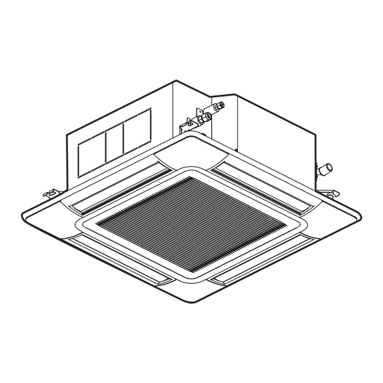
Name of Parts and Indication of Safety Consideration Safety labels are affixed to the indoor unit in order to ensure the safe use. Read and understand this manual before using the indoor unit. For design panel, refer to the manual for the design panel. WARNING Label Motion Sensor (Only for Air Panel with Motion Sensor) Indoor Unit Air Outlet Louver Air Panel (Optional) Air Inlet Grille (The air filter is attached inside.) Indication Place for Indoor Unit Model Wired Controller (Optional) It is indicated on the specification plate The operating condition is attached at the condensate pan. -
Page 12: Wired Controller
Wired Controller Model: PC-ARF1 (Optional) The example below references the control panel and all adjustable settings. The wired controller display may be Display Part different during actual operation. Fan Speed Indicator Swing Louver Indicator Schedule Timer Indicator It is indicated when the schedule timer function is set. (*) Avoid Air and Receive Operation Mode Indicator Indicator It is only for the air panel with Operation Lock Indicator The indications of motion/radiation sensor. (*) It is indicated when the operation “HEAT” and “AUTO” are lock function is set. (*) indicated only for the heat pump type models. Filter Sign Indicator FLTR Room Name It is indicated at the set period for... -
Page 13: Operation Method
Operation Method Refer to the manual for the wired controller. Elevating Grille This function is available only when the elevating grille is equipped with the air panel. This function is for the air inlet grille automatically moves upward or downward from the air panel when cleaning the air filter and air inlet grille. For details, refer to the manual for design panel. < Caution of Setting Elevating Grille into Air Panel After Cleaning > When the air inlet grille is set inside the air panel, ensure that the air inlet grille is horizontal and the wire is suspended tightly without loosening. After the above is ensured, set the air inlet grille. If the air inlet grille is inclined and the wire is loosened, they may be caught in the pulley. It may lead to a failure of the pulley or pulley block. If the worst happens, it may cause personal injury due to falling the air panel. Wire is loosened. Wire Horizontal Slowly push the air inlet grille in the arrow direction. Air Inlet Grille NOTES: • This function is available only when the elevating grille is equipped with the indoor unit. • Make sure that the unit operation is stopped before using the elevating grille. • The elevating grille function is not available when the unit is operated. (1) Select “Elevating Grille” from the “Menu” and press Menu “OK”. - Page 14 (3) Press “ ”. The elevating grille starts lowering. Elevating Grille:All UPDW • Once “ ” is pressed, the elevating grille lowers to the specified height. Press • If “ ” is pressed once again, the elevating grille lowers by 50 cm raise/lower grille. from the present height. (When “ ” is pressed each time, the elevating grille lowers respectively by 50 cm.) Back Rtrn • To stop the elevating grille, press “ ”. NOTE: The first time the indoor unit is turned ON, such as when turning on the power or recovering from a power failure, the air inlet grille will rise even if “ ” is pressed. Once the air inlet grille is set inside the air panel, the air inlet grille can be lowered by pressing “ ”. (4) When the cleaning is finished, press “ ”. Elevating Grille:All UPDW The elevating grille starts rising. The grille will be set inside the air panel and stopped moving after 3 seconds. Press (If the air inlet grille is inclined at this time, press “...
-
Page 15: Motion Sensor
Motion Sensor This setting is available only for the air panel with motion/radiation temperature sensor. 8.1 Function The air panel (P-AP160NAE2) is equipped with four motion sensors and one radiation sensor. ● Motion Sensor Detecting Area These sensors can detect human activity by measuring the level of change in infrared light Area of Motion Sensors emitted by humans or objects. (Divided into four areas ● Radiation Sensor among each air outlet) 123° These sensors can detect the radiation temperature Area of Radiation Sensor of humans or objects by measuring the level of infrared light emitted by humans or objects. approx. I8.8m 8.2 Function 1: Automatic Capacity Save Operation This function can automatically perform the capacity save operation by a human activity in the air-conditioned area. If there is insufficient or absence of human activity in the air-conditioned area, the motion sensors detect it and save the air conditioning capacity. In addition, after the motion sensors detect absence for the period, the operation mode is changed to “If absent”. -
Page 16: Function 2: Adjusting Capacity By Increase Or Decrease In The Number Of People
8.3 Function 2: Adjusting Capacity by Increase or Decrease in the Number of People (1) In instances where people are gathered within or are beyond the range of the motion sensor. The air conditioning capacity is adjusted by the automatic setting temperature correction depending on human activity and movements of a heat source in the detecting area of the motion sensor . Increase in the The setting temperature is adjusted number of people from -1 ºC to -2 ºC. Cooling or Dry Operation Decrease in the The setting temperature is adjusted number of people from +1 ºC to +2 ºC. Increase in the The setting temperature is adjusted number of people from -1 ºC to -2 ºC. Heating Operation Decrease in the The function is invalided. number of people (2) The adjusted setting temperature will return to normal setting temperature after 10 to 30 minutes, depending on the conditions. NOTICE ● If human activity and movements of a heat source are small, the motion sensor cannot detect them. ● If room temperature is high and there is little difference between the radiation temperature of walls, floor space, and humans, the motion sensor may not detect increase or decrease in the number of humans. (For example: The cooling operation is performed with a setting at 30 ºC in the summer season.) ● During the “Capacity Save” and “If absent” phase of operation of Function 1, the Function 2 is unavailable. 8.4 Descriptions for Setting Items ● Motion Sensor Setting The operation mode for activations of functions 1 and 2 can be selected as follows: * “ALL MODES”: Functions 1 and 2 are available when the operation mode is “COOL”, “DRY”, “HEAT”, or “FAN”. -
Page 17: Setting The Motion Sensor
8.5 Setting the Motion Sensor Press “Menu”. Menu Select “Motion Sensor Setting” from the menu by pressing “ ” or “ ” and press Menu 15:10(Fri) Back/Help “OK”. Individual Louver Setting Louver Open/Close VENTI Total Heat Exchanger SET Menu Motion Sensor Setting Sel. Entr Rtrn Back Back/Help "Motion Sensor Setting” is displayed. The highlighted item changes to “Sensor”, “If absent”, and “Check interval” by Motion Sensor Setting pressing “ ” or “ ”. Sensor Menu If absent... - Page 18 Press “ ” or “ ” and select “Check interval”. Motion Sensor Setting Sensor Menu If absent Running Check interval 30MIN Back/Help Sel. Adj. Entr Back Rtrn The display will display: “30MIN”, “60MIN”, “90MIN”, “120MIN”, and “180MIN” in Motion Sensor Setting Sensor order by pressing “ ” or “ ” to change Menu If absent Running the setting. Check interval 30MIN Back/Help If other settings are not required, go to procedure “9”.
-
Page 19: Comfort Setting
Comfort Setting NOTICE ● If two wired controllers are utilized, the comfort setting is available by using the wired controller 1 only. ● When using Wired Controller PC-ARFG1, the display name of the function is different. In < > is the display name in this case. 9.1 Setting of “Control Cool Air” <“GentleCool Comfort”> (Cold Draft Control during Cooling Operation) (1) Function This function controls the overcooling airflow to prevent of cold draft. (2) Setting Items • OFF: This function is not available. • LOW: The over-cooling airflow temperature is controlled low degree. • MED: The over-cooling airflow temperature is controlled medium degree. • HIGH: The over-cooling airflow temperature is controlled high degree. (The default setting is “OFF”) (3) Supplement of Function • The discharge air temperature is elevated higher in “HIGH” > “MED” > “LOW” order. • The recommended discharge air temperature setting is “LOW”. (When feeling cold at “LOW”, change the setting to “MED” or “HIGH”.) * This function also reduces the formation of dew condensation on the air panel when the discharge air temperature is lower than the inlet air temperature in a very humid room. (The recommended discharge air temperature setting is “LOW”.) NOTICE ● The “Control Cool Air” function may not have much effect depending on the operating conditions of the outdoor unit. ● In case one outdoor unit is connected to multiple indoor units and the rate of these indoor units which are equipped with the “Control Cool Air” function is low, this function may not have much of an effect. ● When this function is set, it may take a few minutes to cool the entire room. ● While this function is activated, “Cold draft rest.” is displayed on the LCD control panel of the wired controller. - Page 20 (3) Supplement of Function • The louver angle is adjusted by the motion sensor to compensate for the presence or absence of human activity and can be set for manual override at the wired controller. • Each of the four louvers can move independently of the others. • When the motion sensor detects continuous human activity, louver operation remains at: “Avoid Air” or the “Receive” setting. • If the motion sensor detects an absence of human activity for 15 minutes or longer, louver angles can be adjusted to the “Avoid Air” or “Reserve” settings to save on energy consumption or manually overridden from the wired controller. • The commands: “Avoid Air” and “Receive” are shown on the LCD display as variations of angular louver positioning. See below: Meeting Room Meeting Room MODE SPEED LOUV. TEMP MODE SPEED LOUV. TEMP Avoid Receive COOL COOL MAIN MAIN LOUV. Adj. LOUV. Adj. Avoid Air Receive NOTICE ● The function diminishes to (sleep mode) in times of sparse human activity. To reactivate, stand up and begin walking. ● Objects with higher temperature signatures can be mistaken for humans and can activate this system function.
-
Page 21: Setting Of "Floor Heat Control" [ With P-Ap160Nae2 ]
9.3 Setting of “Floor HEAT Control” [ with P-AP160NAE2 ] This is a function that is enabled when using PC-ARF1. When using PC-ARFG1, the function of item 9.8 is enabled. (1) Function If a steep temperature difference is detected between the radiation temperature and the setting temperature, this function heats the entire room efficiently by adjusting airflow direction and airflow volume. (2) Descriptions for Setting Items: The setting of “Floor HEAT Control” • OFF: This function is unavailable. • ON: This function is available. (The default setting is OFF.) (3) Supplement of Function • When this function is activated, airflow direction is directed downwards and the airflow volume changes to “AUTO”. • This function continues to be active for 20 to 60 minutes, depending on the difference between the ambient air temperature and the set temperature. • This function will repeat, depending on the temperature difference between a radiation temperature and the setting temperature. NOTICE ● If the radiation temperature (Floor Temperature) in the detecting area is low, this function may be activated frequently. ● This louver direction is downward during this function. Avoid a cold draft from a direct airflow by setting function “Individual Louver Setting” or “Avoid Air”. ● During the activation of this function, “Floor HEAT control” is indicated on the LCD. 9.4 Useful Tips on Setting the Swing Louver Direction [ with P-AP160NAE2 ] The swing louver direction can be varied according to each set function. If the set airflow direction is not comfortable, refer to the following descriptions and adjust the airflow direction. Order of Priority for Setting the Swing Louver Direction ● Capacity save operation (Function 1) set as “Motion Sensor Setting”. HIGH ● Setting of “Individual Louver Setting” (Refer to the manual for the wired controller.) ● Swing louver direction at detecting human activity side by “Avoid Air” and “Receive”... -
Page 22: Creating Comfort Settings
9.5 Creating Comfort Settings Press “Menu”. Menu Select "Comfort Setting” from the menu by pressing “ ” or “ ” and press “OK”. Back/Help Menu Back/Help “Motion Sensor Setting” is displayed. The highlighted item is changed to “Control Cool Air”, “Louver in COOL”, “Louver in HEAT” and “Floor HEAT control” by pressing “ ” or “ ”. After selecting set item, set function by pressing “ ” or “ ”. Setting details are as shown below. Menu Back/Help • Control Cool Air: “OFF” ↔ “LOW” ↔ “MED” ↔ “HI” • Louver in COOL: “Normal” ↔ “Avoid Air” ↔ “Receive” • Louver in HEAT: “Normal” ↔ “Avoid Air” ↔ “Receive” • Floor HEAT Control: OFF ↔ ON Press “OK”. The confirmation screen is displayed. Select “Yes” by pressing “ ” or “ ” and press “OK”. The “Comfort Setting” is completed and the LCD indication returns to the normal mode. -
Page 23: Featwarm Heat Air Flow [ With P-Ap160Nae2 ]
NOTICE ● Radiant temperature (temperature near floow surface) may not be detected correctly. ● Air direction becomes horizontal, so if you want to adjust the louver angle, then set. ● During the operation of this control “FloorSense Cool Air FLOW” is displayed on. 9.8 FeetWarm Heat Air Flow [ with P-AP160NAE2 ] (1) Function This control optimizes the airflow during heating and quickly warms this entire room. It operates when the difference between the radiation temperature (temperature near floor surface) and the set temperature is large, and automatically controls the louver angle and fan speed. (2) Descriptions for Setting Items: • OFF: Control do not operate • “Valid∙Short”: The control operates for maximum of 40 minutes. • “Valid∙Long”: The control operates for maximum of 80 minutes. (3) Supplement of Function • This control performs temperature uneven suppression operation after start-up operation. • During start-up operation, air direction of two louvers are facing downward and the other two louvers are horizontal. • During temperature unevenness suppression operation, air direction of three louvers are Auto-Swing, and the remaining one is horizontal. • When setting the “Avoid Air” or “Receive” or “Individual Louver Setting”, air direction of louvers that are not set by these setting are facing downward during start-up operation. • If the setting of “Avoid Air” or “Receive” or “Individual Louver Setting” is performed during start-up operation, the start-up operation is terminated and temperature unevenness suppression operation is performed. • During this control operation, fan speed is automatic. • After the control operation ends, operation will start again if the condition is met. • In case the room require to warm well, please select “Valid∙Long”. If you feel uncomfortable with the air direction, please select “Valid∙Short”. NOTICE • Do not use this function if the air outlet is blocked with optional parts. Heating performance may be extremely degraded. -
Page 24: Other Indications
10. Other Indications 10.1 In Normal Condition 10.1.1 Central Control • When remote control operation is restricted (all functions) “Central Control” and “ ” are turned ON. If the remote control restriction is set from the central controller, the settings for RUN, Operation Mode, Temperature Setting, Fan Speed and Louver will not be accessible from the controller. Turned ON • When remote control operation is restricted (some functions) “ ” is turned ON. The function operation which is restricted from the central controller cannot be set. Turned ON 10.1.2 Motion Sensor Control “Motion sensor ON” is turned ON during the motion sensor control. In this case, the operation is performed with saving the capacity or stopped by the motion sensor control. Meeting Room MODE SPEED LOUV. TEMP HEAT Motion Sensor ON Adj. SPEED Turned ON 10.1.3 Defrost “Defrost” is turned ON and the indoor fan stops during defrosting operation. The louver is fixed in a horizontal position. -
Page 25: Operation Control
10.1.4 Operation Control • Supplying Main Electrical Power “Preheating” is turned ON at power-on. In this case, the compressor is under preheating. Do not turn OFF the power supply of the outdoor unit during the high season for Cooling/Heating operation. Otherwise, the operation might not be available for Max. 4 hours. Turned ON • During Hot Start (for Heating Operation Only) “HOT-START” is turned ON. Turned ON • Different Operation Mode When the operation mode set by the wired controller is different from the outdoor unit operation mode, the actual operation mode flashes on the LCD. (except for the heat recovery system models) The current operation mode and the message “Other remote are in HEAT setting” will be flashing. Flashing The above display shows the case that the cooling mode is set from the wired controller while actual operation mode of the outdoor unit is heating. A10526930A-rev.2... -
Page 26: Automatic Heating/Cooling Operation
An automatic heating/cooling operation requires extra settings. Refer to the “Installation & Maintenance Manual” for the wired controller and the “Service Manual” for details. 10.1.5 Automatic Heating/Cooling Operation In case dual setpoint is selected in automatic heating/cooling operation, during auto mode both cooling setpoint and heating setpoint can be selected. By default, temperature when the heating/cooling mode changes are as follows. Cooling mode changes to heating mode when the indoor temperature is heating setpoint -1 ºC. Heating mode changes to cooling mode when the indoor temperature is cooling setpoint +1 ºC. If the temperature for changing modes requires to be changed, refer to the “Installation & Maintenance Manual” for the wired controller and the “Service Manual” for details. Meeting Room MODE SPEED LOUV. TEMP Avoid COOL HEAT AUTO LOUV. HEAT TEMP Adj. A setback operation requires extra settings. Refer to the “Installation & Maintenance Manual” for the wired controller and the “Service Manual” for details. 10.1.6 Setback Operation Setback operation is mainly to sustain a comfort room air temperature while occupants are out of the room. If the setback operation is enabled, the setpoint is adjusted for setback. During this time, “Setback” is displayed on the LCD. Refer to the “Installation & Maintenance Manual” for the wired controller and the “Service Manual” for details. Meeting Room MODE SPEED LOUV. TEMP Avoid AUTO Setback... -
Page 27: Automatic Control
11. Automatic Control This air conditioner automatically starts the following operations according to the indoor conditions. The system is equipped with the following functions. ▪ Enforced Stoppage: The compressor remains off for at least three minutes once it has stopped. If the system is started within approximately three minutes after it has stopped, the RUN indicator is activated. However, the cooling operation or the heating operation remains off and does not start until after three minutes has elapsed. Three-Minute Guard ▪ Enforced Operation: If all indoor units of the system are Thermo-OFF within approximately three minutes after the compressor has started, the compressor operate continuously during those three minutes. However, if all indoor units of the system are stopped by a controller, compressor has stopped. When the indoor unit is operating at a low discharge air temperature, the Frost Prevention cooling operation may be changed to fan operation for a while to avoid frost formation on the indoor heat exchanger. The expansion valve self-cleaning when the cooling operation has stopped. Self-Cleaning of Cooling The sound of which the refrigerant flows may be heard from the indoor unit Expansion Valve and Dry during the self-cleaning. This is not abnormal. Fan Operation When the power saving operation is performed, the louver control is during Power changed to auto mode or fixed downward angle. The LCD on the wireless controller indicates it has not changed. Saving Control To prevent cold air discharge in the room, the fan speed is controlled from the slow position and the low position and then to the set position Hot Start according to the discharge air temperature. At this time the louver is fixed horizontally and “HOT-START” is displayed on the LCD of the wired controller. -
Page 28: Simultaneous Operation
12. Simultaneous Operation The multiple indoor units can simultaneously be controlled by one wired controller (Single: max. 16 units, Twin: max. 8 sets, Triple: max. 5 sets, Quad: max. 4 sets). Contact a distributor or a contractor for detail. 13. Maintenance ● Turn OFF the power supply before the maintenance work. If not, it may cause a fire or an electric shock. ● When cleaning, do not allow water inside the air conditioner. Water on electrical equipment may cause electric shock. -
Page 29: Daily Maintenance
13.1 Daily Maintenance 13.1.1 Cleaning Air Filter Clean the air filter when the filter sign is turned ON. Filter Sign Meeting Room FLTR MODE SPEED LOUV. TEMP Avoid COOL Motion Sensor ON LOUV. Adj. Menu On/Off Back/Help ECO (1) Open the air inlet grille. < In the case of Normal Panel > While sliding the knobs on both side of the air inlet grille in the arrow direction, open the air inlet grille. Air Inlet Grille Knobs < In the case of Elevating Grille > The air panel with air inlet grille lowers the air inlet grille. Refer to Section 7, “Elevating Grille”. (2) Remove the air filter. < In the case of Normal Panel > Hold the lower side of the air inlet grille keeping it inclined. Remove the hooks of air filter from the air inlet grille and remove the air filter. Upper Part of Filter Hook Air Inlet Grille... - Page 30 (3) Clean the air filter. • Vacuum dust with a cleaner, or wash the air filter with water or neutral detergent. • Dry the air filter in the shade. NOTE ● Do not use hot water more than 50 ºC. The air filter may be deformed by heat. ● Do not dry the air filter with open fire, a dryer or a heater. The air filter may be deformed. (4) Attach the air filter. After the air filter is dried, attach it correctly to the air inlet grille. NOTE ● Be sure to attach the air filter. If the indoor unit is operated without the air filter, it may cause malfunction of the indoor unit. ● Make sure that the air inlet grille is securely locked with the knobs. If it is not properly locked, it might open suddenly, resulting in the grille falling. (5) Close the air inlet grille. (6) Reset the filter sign. NOTE If the accumulated operation time is shorter than the filter sigh setting, the indication “ ” is turned ON and “Setting Disabled” will be displayed. • Press “Menu”. Select “Reset Filter Sign Time” from the menu and press “OK”. The confirmation screen will be displayed. Menu 15:10(Fri) Simple Timer Reset Filter Sign Time Operation Schedule Elevating Grille Power Saving Setting...
-
Page 31: Removing, Attaching And Cleaning Air Inlet Grille
13.1.2 Removing, Attaching and Cleaning Air Inlet Grille NOTICE ● Wipe the air inlet grille with a soft cloth soaked in lukewarm water and squeezed. ● Use a soft cloth to clean the air inlet grille and the air panel. If benzine, thinner or detergent (with surfactant) is used to cleaning, the resin part may get discolored or deformed. In addition, note that the parts around the air outlet (louver, guide, etc.) may be damaged if an excessive force is applied. The air inlet grille can be removed and cleaned. < In the case of Normal Panel > (1) Open the air inlet grille. While sliding the knobs on both side of the air inlet grille in the arrow direction, open the air inlet grille. Air Inlet Grille Knobs (2) Remove the air inlet grille. • Unlock the supporting string from the air panel. Supporting String • Open the air inlet grille at an approximately 45º angle from the air panel surface. • Tilt the air inlet grille and lift it up to remove it. Hook on Air Inlet Grille Lift Up Air Inlet Grille Pull to Remove Air Inlet Grille Air Inlet Grille Tilt... -
Page 32: Maintenance Beginning And Ending Of Use
(3) Clean the air inlet grille. NOTE ● Please hold it firmly by hand. Use a soft cloth to clean the air inlet grille and makeup panel. The use of benzene, thinner, detergent (containing a surfactant), etc. may cause the resin part to become discolored or deformed. Also, be especially careful of parts around the air outlet (louver guide, etc.), as excessive force may cause damage. ● Do not dry with direct heat, dryer, heater, etc. It may cause deformation of the resin part. ● Do not touch the radiation temperature sensor lens during cleaning. (4) Attach the air inlet grille. Attach the air inlet grille in the reverse procedure to removing. < In the case of Elevating Grille > Refer to the manual for design panel. 13.2 Maintenance Beginning and Ending of Use < At Beginning of Use > • Remove obstacles around the air inlet grilles and the air outlet of the indoor unit and outdoor unit. • Check that the air filter is not clogged with dust and dirt. < At End of Use > • Clean the air filter, the air inlet grille and the air panel. A10526930A-rev.2... -
Page 33: Troubleshooting
14. Troubleshooting 14.1 This is Not Abnormal Phenomenon Cause and Action All indication lamps on the The micro-computer is activated to protect the wired controller are turned device from electromagnetic waves. Restart the OFF. operation. The operation is stopped automatically because the motion sensor is set as “If absent: OFF” and “Motion Sensor ON” is turned it detects as absence for a period of time. (All the Operation Stopped ON on the wired controller. indoor units connected to the same wired controller are stopped.) Restart the operation. If the instantaneous power After Power Failure failure is within 2 seconds, the operation restarts automatically. This might occur during the defrosting operation in White Steam During Heating Operation the heating operation. from Indoor Unit At Beginning of Heating This might occur when dust attached to the heat White Smoke Operation Season exchanger has been dried. -
Page 34: Before Contact
14.2 Before Contact Check the items before contacting a contractor. Trouble Checking Point Action Check that the main power Turn ON the main power supply for the air supply is turned ON. conditioner. Check that the fuse is not Replace the fuse or reset the circuit breaker. Operation Unavailable blown out or the circuit If the trouble recurs, contact your contractor or breaker of main power supply distributor. is not tripped. Check that the air inlet and outlet of the outdoor unit are Cooling Remove objects covering the air inlet and outlet. not covered with a paper, a vinyl or other objects. Immediate Check that there are any Shutdown After obstacles preventing the air Start-up flow near the air inlet and Heating Remove the obstacles preventing the air flow. outlet of the outdoor unit. Check that the outlet air is not short-circuited to the air inlet. Check that the operation If the fan mode is selected, switch the operation mode is appropriate. -
Page 35: Contact Distributor
14.3 Contact Distributor If trouble still persists, even after checking off previously listed items or detecting problems not mentioned in the previous pages, stop using this product and call your distributor or contractor immediately. If there is any perceived abnormality present (noises or odors associated with electrical short, fire, or burning elements), shut down immediately and shut OFF at the main power supply. Contact your distributor or contractor without delay. Trouble Action before Contact Protection devices (fuses, breakers, and ELB's) activate... -
Page 36: Alarm Code
Discharge Gas Thermistor Failure Outdoor Fan Activation of Fan Controller Protection Evaporating Thermistor Failure Abnormality of Fan Controller Low Pressure Sensor Failure Incorrect Setting of Unit Model System Incorrect Capacity Setting of Incorrect Setting of Unit and Outdoor Unit and Indoor Unit Refrigerant Cycle No. System Incorrect Setting of Other Indoor Unit Compressor Compressor Protection Alarm Number Product origin: MADE IN JAPAN © 2020 Hitachi-Johnson Controls Air Conditioning, Inc. 1-16-1, Kaigan Minato-ku, Tokyo 105-0022, Japan A10526930A-rev.2, 2024 Printed in Japan...
Need help?
Do you have a question about the RCI-1.0FSRP and is the answer not in the manual?
Questions and answers