Table of Contents
Advertisement
Quick Links
Advertisement
Chapters
Table of Contents

Related Manuals for Kaysun Magnus KUE 200 DN11


Summary of Contents for Kaysun Magnus KUE 200 DN11
- Page 1 ENGINEERING DATA BOOK Magnus Series Outdoor Units (20-33,5kW) KUE 200 DN11 KUE 280 DN11 KUE 335 DN11 KUE 224 DN11 Original Manual: Read this manual carefully before using the product, and keep it for future reference. All the pictures in this manual are for illustration purpose only.
- Page 3 Magnus Series Outdoor Unit CONTENTS Part 1 General Information ................3 Part 2 Outdoor Unit Engineering Data ..............7 Part 3 System Design and Installation ............29...
- Page 4 Magnus Series Outdoor Unit...
-
Page 5: General Information
Magnus Series Outdoor Unit Part 1 General Information 1 Indoor and Outdoor Unit Capacities ............4 2 External Appearance ..................5... -
Page 6: Outdoor Units
Magnus Series Outdoor Unit 1 Indoor and Outdoor Unit Capacities 1.1 Outdoor Units Table 1-1.5: Outdoor unit capacity range Model Name Combination Type KUE 200 DN11 KUE 224 DN11 KUE 280 DN11 KUE 335 DN11 Notes: Magnus series outdoor units could not be combined. -
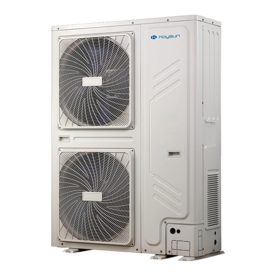
Page 7: External Appearance
Magnus Series Outdoor Unit 2 External Appearance 2.1 Outdoor Units KUE 200 DN11 KUE 224 DN11 KUE 280 DN11 KUE 335 DN11... - Page 8 Magnus Series Outdoor Unit...
-
Page 9: Table Of Contents
Magnus Series Outdoor Unit Part 2 Outdoor Unit Engineering Data 1 Specifications ....................8 2 Dimensions .....................10 3 Installation Space Requirements .............11 4 Piping Diagrams ..................12 5 Wiring Diagrams ..................14 6 Electrical Characteristics .................15 7 Functional Components and Safety Devices ..........16 8 Capacity Tables ..................17 9 Operating Limits ..................25 10 Sound Levels ..................26... -
Page 10: Specifications
Magnus Series Outdoor Unit 1 Specifications Model name KUE 200 DN11 KUE 224 DN11 Power supply V/Ph/Hz 380-415V, 3N~, 50Hz 20.00 22.40 Capacity kBtu/h 68.20 76.40 Cooling Power input 5.15 6.79 3.88 3.30 20.00 22.40 Capacity kBtu/h 68.20 76.40 Heating Power input 4.43 5.32... - Page 11 Magnus Series Outdoor Unit Model name KUE 280 DN11 KUE 335 DN11 Power supply V/Ph/Hz 380-415V, 3N~, 50Hz 28.00 33.50 Capacity kBtu/h 95.50 114.30 Cooling Power input 13.02 15.02 2.15 2.23 28.00 33.50 Capacity kBtu/h 95.50 114.30 Heating Power input 7.61 9.23 3.68...
-
Page 12: Dimensions
Magnus Series Outdoor Unit 2 Dimensions 1120... -
Page 13: Installation Space Requirements
Magnus Series Outdoor Unit 3 Installation Space Requirements For single unit installation (Wall or obstacle) Air inlet >300 Maintain the electric wire and pipeline Air inlet >600 Air outlet For single-row installation Parallel connect the two units or above (unit: mm) >300 >600 >600... -
Page 14: Piping Diagrams
Magnus Series Outdoor Unit 4 Piping Diagrams KUE 200 DN11; KUE 224 DN11; KUE 280 DN11 piping diagram KUE 335 DN11 piping diagram Legend Parts name Parts name Compressor Stop valve (gas side) High pressure switch Stop valve (liquid side) High pressure sensor Heat exchanger temperature sensor Oil separator... - Page 15 Magnus Series Outdoor Unit Key components: 1. Oil separator: Separates oil from gas refrigerant pumped out of the compressor and quickly returns it to the compressor. Separation efficiency is up to 99%. 2. Accumulator: Stores liquid refrigerant and oil to protect compressor from liquid hammering. 3.
-
Page 16: Wiring Diagrams
Magnus Series Outdoor Unit 5 Wiring Diagrams... -
Page 17: Electrical Characteristics
Magnus Series Outdoor Unit 6 Electrical Characteristics Outdoor unit electrical characteristics Power Supply Compressor Min. Max. Model Volts TOCA volts volts KUE 200 DN11 380~415 24.3 2×0.17 2.1+2.1 KUE 224 DN11 380~415 24.3 12.4 2×0.17 2.1+2.1 KUE 280 DN11 380~415 24.3 18.4 2×0.17... -
Page 18: Functional Components And Safety Devices
Magnus Series Outdoor Unit 7 Functional Components and Safety Devices KUE 200 DN11 KUE 224 DN11 Item KUE 280 DN11 KUE 335 DN11 Compressor discharge pipe 90°C = 5kΩ ± 3% temperature sensor Compressor Crankcase heater 25W × 2 Inverter module temperature Inverter module 90°C = 5kΩ... -
Page 19: Capacity Tables
Magnus Series Outdoor Unit 8 Capacity Tables 8.1 Cooling Capacity Tables KUE 200 DN11 cooling capacity Indoor temperature(°C DB/WB) Combination Outdoor DB:20.8,WB:14 DB:23.3,WB:16 DB:25.8,WB:18 DB:27,WB:19 DB:28.2,WB:20 DB:30.7,WB:22 DB:32,WB:24 (%) (Capacity temperature index) (°C DB) 14.03 1.89 16.47 2.06 19.72 2.27 20.00 2.67 21.69... - Page 20 Magnus Series Outdoor Unit KUE 224 DN11 cooling capacity Indoor temperature(°C DB/WB) Combination Outdoor DB:20.8,WB:14 DB:23.3,WB:16 DB:25.8,WB:18 DB:27,WB:19 DB:28.2,WB:20 DB:30.7,WB:22 DB:32,WB:24 (%) (Capacity temperature index) (°C DB) 15.72 2.42 18.45 2.64 22.09 2.91 22.40 3.42 24.29 3.34 27.92 3.70 28.77 4.08 15.72 2.46...
- Page 21 Magnus Series Outdoor Unit KUE 280 DN11 cooling capacity Indoor temperature(°C DB/WB) Combination Outdoor DB:20.8,WB:14 DB:23.3,WB:16 DB:25.8,WB:18 DB:27,WB:19 DB:28.2,WB:20 DB:30.7,WB:22 DB:32,WB:24 (%) (Capacity temperature index) (°C DB) 19.64 4.30 23.06 4.69 27.61 5.17 28.00 6.07 30.36 5.93 34.90 6.56 35.96 7.24 19.64 4.36...
- Page 22 Magnus Series Outdoor Unit KUE 335 DN11 cooling capacity Indoor temperature(°C DB/WB) Combination Outdoor DB:20.8,WB:14 DB:23.3,WB:16 DB:25.8,WB:18 DB:27,WB:19 DB:28.2,WB:20 DB:30.7,WB:22 DB:32,WB:24 (%) (Capacity temperature index) (°C DB) 23.50 5.48 27.59 5.97 33.03 6.58 33.50 7.72 36.32 7.54 41.75 8.35 43.02 9.21 23.50 5.55...
-
Page 23: Heating Capacity Tables
Magnus Series Outdoor Unit 8.2 Heating Capacity Tables KUE 200 DN11 heating capacity Indoor air temp. °C DB Outdoor air temp. °C DB °C WB -19.8 18.43 7.07 18.36 7.15 18.29 7.23 18.29 7.27 18.29 7.31 18.21 7.40 -18.8 18.71 7.09 18.64 7.17... - Page 24 Magnus Series Outdoor Unit KUE 280 DN11 heating capacity Indoor air temp. °C DB Outdoor air temp. °C DB °C WB -19.8 25.80 10.37 25.70 10.49 25.60 10.60 25.60 10.67 25.60 10.73 25.50 10.86 -18.8 26.20 10.40 26.10 10.51 26.00 10.63 26.00 10.68...
- Page 25 Magnus Series Outdoor Unit 8.3 Capacity Correction Factors for Piping Length and Level Difference Rate of change in cooling capacity Rate of change in heating capacity H(m) H(m) 10 20 30 40 50 60 70 80 90 100 110 120 10 20 30 40 50 60 70 80 90 100 110 120 L(m) L(m)
- Page 26 Magnus Series Outdoor Unit 8.4 Capacity Correction Factors for Frost Accumulation The heating capacity tables do not take account of the reduction in capacity when frost has accumulated or while the defrosting operation is in progress. If snow has accumulated against the outside surface of the outdoor unit heat exchanger heating capacity is reduced.
-
Page 27: Operating Limits
Magnus Series Outdoor Unit 9 Operating Limits Cooling operating limits Heating operating limits 10 15 20 25 30 35 10 15 20 25 30 35 Indoor temperature (°C DB) Indoor temperature (°C DB) Notes: 1. These figures assume the following operating conditions: ▪... -
Page 28: Sound Levels
Magnus Series Outdoor Unit 10 Sound Levels 10.1 Overall Sound pressure level Model dB(A) KUE 200 DN11 KUE 224 DN11 KUE 280 DN11 KUE 335 DN11 Notes: Sound pressure level is measured at a position 1000mm in front of the unit and (H+1000)/2mm above the floor in a semi-anechoic chamber. During in- situ operation, sound pressure levels may be higher as a result of ambient noise. - Page 29 Magnus Series Outdoor Unit KUE 280 DN11 octave band level NC-70 NC-60 NC-50 NC-40 NC-30 Approximate minimum audible limit on continuous noise NC-20 1000 2000 4000 Octave band center frequency (Hz) KUE 335 DN11 octave band level NC-70 NC-60 NC-50 NC-40 NC-30 Approximate minimum...
-
Page 30: Optional Accessories
Magnus Series Outdoor Unit 11 Accessories 11.1 Standard Accessories Name Shape Quantity Function Outdoor unit installation manual Outdoor unit owner's manual Installation inststructions: Indoor unit manifold Water outlet connection pipe Used for outdoor drainage Matched resistor Enhances communication stability Waterproof chassis cover Used for centralized drainage Connection pipe(26/28/33.5kW) Connecting pipes... -
Page 31: Installation
Magnus Series Outdoor Unit Part 3 System Design and Installation 1 Preface to Part 3 ..................30 2 Unit Placement and Installation ..............31 3 Drain Piping ....................34 4 Insulation ....................37 5 Charging Refrigerant ...................39 6 Installation in Areas of High Salinity ............41 7 Appendix to Part 3 –... -
Page 32: Preface To Part 3
The information contained in this Engineering Data Book may primarily be of use during the system design stage of a Kaysun Magnus Series Units project. Additional important information which may primarily be of use during field installation has been placed in boxes, such as the example below, titled “Notes for installers”. -
Page 33: Unit Placement And Installation
Magnus Series Outdoor Unit 2 Unit Placement and Installation 2.1 Outdoor Units 2.1.1 Placement considerations Placement of outdoor units should take account of the following considerations: ▪ Air conditioners should not be exposed to direct radiation from a high-temperature heat source. ▪... - Page 34 Magnus Series Outdoor Unit 2.1.3 Base structures Outdoor unit base structure design should take account of the following considerations: ▪ A solid base prevents excess vibration and noise. Outdoor unit bases should be constructed on solid ground or on structures of sufficient strength to support the units’ weight. ▪...
-
Page 35: Indoor Units
Magnus Series Outdoor Unit 2.1.5 Acceptance and unpacking Notes for installers ▪ When units are delivered check whether any damage occurred during shipment. If there is damage to the surface or outside of a unit, submit a written report to the shipping company. ▪... -
Page 36: Drain Piping
Magnus Series Outdoor Unit 3 Drain Piping 3.1 Design Considerations Drain piping design should take account of the following considerations: ▪ Indoor unit condensate drain piping needs to be of sufficient diameter to carry the volume of condensate produced at the indoor units and installed at a slope sufficient to allow drainage. Discharge as close as possible to the indoor units is usually preferable. - Page 37 Magnus Series Outdoor Unit Figure 3-5.5: Drain piping air vents Vent ▪ Air conditioner drain piping should be installed separately from waste, rainwater and other drain piping and should not come into direct contact with the ground. ▪ Drain piping diameter should be not less than the indoor units’ drain piping connection. ▪...
- Page 38 Magnus Series Outdoor Unit Table 3-5.2: Vertical drain piping diameters Nominal diameter PVC piping Capacity (L/h) Remarks (mm) PVC25 Branch piping only PVC32 PVC40 PVC50 1440 PVC63 2760 Branch or main piping PVC75 5710 PVC90 8280 3.4 Drain Piping for Units with Lift Pumps Drain piping for units with lift pumps should take account of the following additional considerations: ▪...
-
Page 39: Insulation
Magnus Series Outdoor Unit 3.6 Watertightness Test and Water Flow Test Once installation of a drainage piping system is compete, watertightness and water flow tests should be performed. Notes for installers Watertightness test ▪ Fill the piping with water and test for leakages over a 24-hour period. Water flow test (natural drainage test) ▪... -
Page 40: Insulation Material
Magnus Series Outdoor Unit 4.1.4 Installation of piping insulation With the exception of joint insulation, insulation should be applied to piping before fixing the piping in place. Insulation at joints in refrigerant piping should be applied after the gas tightness test has been completed. Notes for installers ▪... -
Page 41: Charging Refrigerant
Magnus Series Outdoor Unit 5 Charging Refrigerant 5.1 Calculating Additional Refrigerant Charge The additional refrigerant charge required depends on the lengths and diameters of the outdoor and indoor liquid pipes. Table 3-7.1 shows the additional refrigerant charge required per meter of equivalent pipe length for different diameters of pipe. - Page 42 Magnus Series Outdoor Unit … box continued from previous page Step 3 ▪ Open the valve where the yellow hose meets the pressure gauge, and open the refrigerant tank slightly to let the refrigerant eliminate the air. Caution: open the tank slowly to avoid freezing your hand. ▪...
-
Page 43: Installation In Areas Of High Salinity
Magnus Series Outdoor Unit 6 Installation in Areas of High Salinity 6.1 Caution Do not install outdoor units where they could be directly exposed to sea air. Corrosion, particularly on the condenser and evaporator fins, could cause product malfunction or inefficient performance. Outdoor units installed in seaside locations should be placed such as to avoid direct exposure to the sea air and additional anticorrosion treatment options should be selected, otherwise the service life of the outdoor units will be seriously affected. -
Page 44: Appendix To Part 3 - System Commissioning Report
Magnus Series Outdoor Unit 7 Appendix to Part 3 – System Commissioning Report A total of up to 4 report sheets should be completed for each system: ▪ One Sheet A, one Sheet B and one Sheet C per system. ▪... - Page 45 Magnus Series Outdoor Unit Magnus Series System Commissioning Report – Sheet A SYSTEM INFORMATION Project name and location Customer company System name Installation company Commissioning date Agent company Outdoor ambient temp. Commissioning engineer Model Serial no. Power supply (V) Outdoor unit information OUTDOOR UNIT Compressor suction pipe Current (A)
- Page 46 Magnus Series Outdoor Unit Magnus Series System Commissioning Report – Sheet B SYSTEM INFORMATION Project name and location Customer company System name Installation company Commissioning date Agent company Outdoor ambient temp. Commissioning engineer Model Serial no. Power supply (V) Outdoor unit information OUTDOOR UNIT Compressor suction pipe Current (A)
- Page 47 RECORD OF ISSUES SEEN DURING COMMISSIONING Description of observed issue Suspected cause Troubleshooting undertaken Serial no. of relevant unit OUTDOOR UNIT FINAL CHECKLIST SW2 system check performed? Any abnormal noise? Any abnormal vibration? Fan rotation normal? Commissioning engineer Dealer Kaysun representative Name: Signature: Date:...
- Page 48 Magnus Series Outdoor Unit Magnus Series System Commissioning Report – Sheet D Project name and location System name Observed values DSP1 Cooling Heating Parameters displayed on DSP2 Remarks content mode mode 0.-- Unit capacity (Hp) Actual value = value displayed 1.-- Setting number of indoor units 2.--...
- Page 49 Ver. 202407...
Need help?
Do you have a question about the Magnus KUE 200 DN11 and is the answer not in the manual?
Questions and answers