
Related Manuals for Snap-On ATI TOOLS ATI520CT


Summary of Contents for Snap-On ATI TOOLS ATI520CT
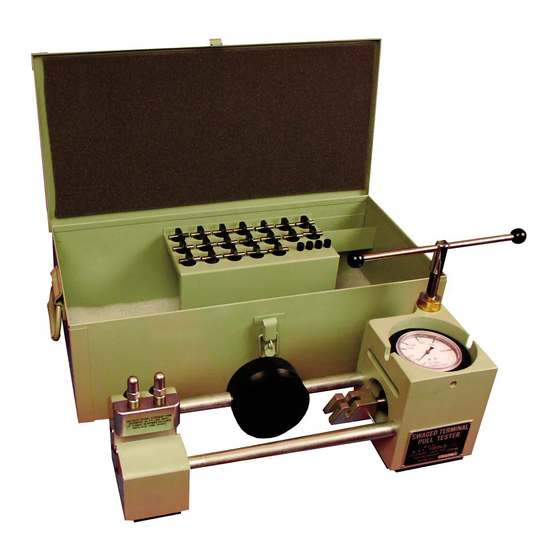
- Page 1 PORTABLE CABLE TERMINAL PULL TESTER ATI520CT ATI520CTK Operating and Maintenance Manual (Revised April 2019) Shipping Dimensions: 30"L x 17"W x 14”H. Shipping Weight: 40 lbs.
- Page 2 AT520CT – Portable Cable Terminal Pull Tester Operating and Maintenance Manual AT520CT Portable Cable Terminal Pull Tester Page 1 of 13...
- Page 3 AT520CT – Portable Cable Terminal Pull Tester Operating and Maintenance Manual Figure 1 – Cable Terminal Tester Assembly Vise Screws Vise Terminal & Cable Assembly Loading Head Hook Adjusting Screw Tension Gauge T-Handle Socket Wrench Tension Adjusting Screw Cinch Block Vise Jaw (Steel Holders w/Copper Jaw Inserts) To operate this unit effectively, please follow this simple procedure: 1.
- Page 4 AT520CT – Portable Cable Terminal Pull Tester Operating and Maintenance Manual 9. Push the vise jaws toward the loading head until they shoulder against the vise ----- CAUTION ----- The vise jaws must be tightened down securely to eliminate the possibility of the cable slippage during testing.
- Page 5 AT520CT – Portable Cable Terminal Pull Tester Operating and Maintenance Manual AT520CTK – Portable Cable Terminal Pull Tester Kit CARBON STEEL WIRE ROPE CABLE MIL-DTL-83420 TYPE I COMP A Minimum Proof load Proof load Breaking Strength BRAID 1/16 7 X 7 3/32 7 X 7 1200...
- Page 6 AT520CT – Portable Cable Terminal Pull Tester Operating and Maintenance Manual The complete kit consists of: Item Item Description / Cable Diameter Reference Terminals Legacy UNIT 1 pr ATI520CTD2 COPPER JAWS-1/16" AT520CTD-2 1 pr ATI520CTD3 COPPER JAWS-3/32" AT520CTD-3 1 pr ATI520CTD4 COPPER JAWS-1/8"...
- Page 7 AT520CT – Portable Cable Terminal Pull Tester Operating and Maintenance Manual MAINTENANCE How to fill the Pull Tester Oil System Piston Assembly Seal Gauge Opening Hook Sleeve Loading Head Housing Tension Adjusting Screw Adjusting Screw Lens Bushing Gauge Figure 7 – Filling the Oil System 1.
- Page 8 AT520CT – Portable Cable Terminal Pull Tester Operating and Maintenance Manual How to Bleed the Pull Tester Oil System 1. If air is suspected to be in the system, fill the system with hydraulic oil. (See “How to Fill the Pull Tester Oil System.) 2.
- Page 9 AT520CT – Portable Cable Terminal Pull Tester Operating and Maintenance Manual How to Calibrate the Pull Tester Washer Gauge Vise Screws Tension Adjusting Screw Vise Adapter Adjusting Screw Hook Force Gauge Hook Adapter Cinch Block Screw Loading Head Figure 9 – Calibrating the Pull Tester 1.
- Page 10 AT520CT – Portable Cable Terminal Pull Tester Operating and Maintenance Manual 7. Install the force gauge as shown in Figure 9. Secure the force gauge to the vise adapter with the and to the hook adapter with the pin 8. Remove any slack in the linkage by turning the screw clockwise.
- Page 11 AT520CT – Portable Cable Terminal Pull Tester Operating and Maintenance Manual Table 1 Gauge Settings Pull Tester Gauge Reading (Pounds) Cable Size (Inches) (60% of rated strength of the cable) 1/16 3/32 1200 5/32 1680 3/16 2520 7/32 3360 4200 Figure 10 –...
- Page 12 AT520CT – Portable Cable Terminal Pull Tester Operating and Maintenance Manual Figure 11 – AT520CT - Portable Cable Terminal Pull Tester – Exploded View Page 11 of 13...
- Page 13 AT520CT – Portable Cable Terminal Pull Tester Operating and Maintenance Manual AT520CT Parts List (Index numbers refer to Figure 11) Index # Part # Part Name # Required T-Handle Socket Wrench (5/8”) AT520CTA AT259RG-8 Screw AT520CT-41 Screw AT520CT-40 Bushing AT520CT-39 Cinch Block AT520CT-9 AT520CT-14...
- Page 14 BACT14A-4 ATI520CTSB-5 BACT14A-5 ATI520CTSB-6 BACT14A-6 NOTE: ATI520CTSB Series adaptors must be used with the ATI520CTS-6 adaptor to perform pull test operation. Snap-on Specialty Tools 19220 San Jose Avenue City of Industry, CA 91748 Phone (626) 965-0668 Page 13 of 13...
Need help?
Do you have a question about the ATI TOOLS ATI520CT and is the answer not in the manual?
Questions and answers