Table of Contents
Advertisement
Advertisement
Table of Contents

Related Manuals for Snap-On EETA308D


Summary of Contents for Snap-On EETA308D
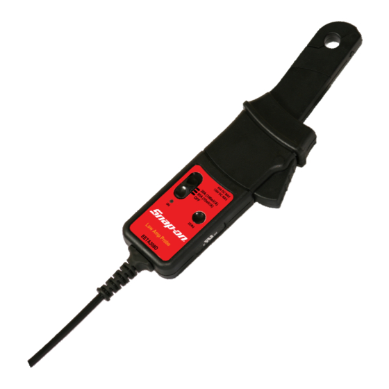
- Page 1 Low Amp Probe EETA308D Reference Manual...
- Page 3 SAFETY WARNING Risk of Personal injury • Do not apply over 150 VAC (RMS) or DC. • Do not change the battery while the instrument is attached to a power source. Make sure the unit power is “OFF” before opening the battery compartment.
- Page 4 SAFETY Safety Standards BSEN61010-1: 2001 BSEN61010-2-032: 2002 BSEN61010-031: 2002 150 V , Category I Rated Transient Overvoltage 800V Pollution Degree 2 EMC Standards BSEN 61326-2- 2:2006 1998 FCC Part 15 Class B...
- Page 5 SAFETY The following symbols appear on the products: WARNING Read instruction manual and safety messages before using product Double/Reinforced Insulation. Read all instructions completely before using this product. To avoid electric shock; use caution during installation and use of this product. High voltages and currents may be present in circuit under test.
- Page 6 Low Amp Probe EETA308D Reference Manual March 2011...
- Page 7 The information, specifications and illustrations in this manual are based on the latest information available at the time of publication. The manufacturer reserves the right to make equipment changes at any time without notice. ©2011 Snap-on Incorporated...
-
Page 8: Table Of Contents
Contents Page 1.0 Introduction ............2 2.0 Specifications ............3 2.1 Electrical Data............3 2.2 General Data ............3 3.0 Operating Instructions ........4 3.1 Connecting the Probe ..........4 3.2 Switch on ..............4 3.3 Low Amp Current Probe Zero Adjustment ....4 3.4 Error Factor ............ -
Page 9: Introduction
60 Amps with a resolution of 1mA over the frequency range of DC to 50 kHz. The probe has two scales, 0 to 20 Amps and 0 to 60 Amps. The Snap-on Low Amp Current Probe outputs an analog voltage based on current flow through the circuit. -
Page 10: Specifications
2.0 SPECIFICATIONS 2.1 Electrical Data Current ranges : 20A / 60A AC PEAK or DC Measuring range : +/- 20A / 60A Output sensitivity : 100mV / 10mV/A Accuracy (20A Range) : +/- 1% of reading +/- 5mA Accuracy (60A Range) : +/- 2% of reading +/- 50mA Resolution : +/- 1mA / 10mA Load impedance... -
Page 11: Operating Instructions
The Battery Replacement procedure is described in section 5.0. 3.3 Low Amp Current Probe Zero Adjustment The Snap-on Low Amp Current Probe has a push button auto zero feature. The output zero offset voltage of the probe may change due to thermal shifts and other environmental conditions. -
Page 12: Reading The Mv Scale
3.5 Reading the mV scale When reading the millivolt scale, remember that a probe setting of 100mV equals 1 Amp (20Amp scale on the Snap-on Low Amp Current Probe). Similarly: A reading of: 0.8mV = 8mA A reading of: 1.8mV= 18mA A reading of: 21.8mV = 218mA... - Page 13 3.6.2 Fuel Pump Current Measurement Recommended Probe Setting: 20A Note: Before taking measurements or clamping the probe jaws around any wire, complete the Setup steps below. Setup 1. Use the On/Off and Range Selector switch to select the 20A setting. 2.
- Page 14 Tech Note If the fuel pump is difficult to access, it may be possible to check the fuel pump current at the fuse box (if applicable). To check the fuel pump current at the fuse box: 1. Locate fuse box and remove the fuel pump fuse. 2.
- Page 15 Figure 4. If the vehicle is DIS equipped, current flow through each coil should be about the same. If the ignition coil waveform has a sharp rise at the beginning of the ramp upward, suspect shorted coil windings (refer to Figure 5). Figure 5.
- Page 16 Test To measure injector current: 1. Clamp the Low Amp Current Probe around the B+ side or the control side wire of injector. Do not clamp the probe around both wires. 2. Verify that the probe jaws are fully closed. The injector current readings display.
-
Page 17: Current Probe Characteristics
4.0 CURRENT PROBE CHARACTERISTICS Frequency Response 0.00 -0.50 -1.00 -1.50 -2.00 -2.50 -3.00 0.01 Frequency (kHz) Typical Linearity in 20A Range 2000 1500 1000 -500 -1000 -1500 -2000 Input Current (A) Typical Linearity in 60A Range -200 -400 -600 Input Current (A) -
Page 18: Battery Replacement
(refer to Figure 9). When replacing the battery, use the 9-volt alkaline (PP3/MN1604) type only. Using any other type of battery in the Snap-on Low Amp Current Probe will invalidate your warranty. To replace the battery: 1. -
Page 19: Cleaning
6.0 CLEANING Clean the case periodically by wiping it with a damp cloth and detergent. Do not use abrasive cleaners or solvents. Do not immerse the probe in liquids. -
Page 20: Warranty
THAT SNAP-ON ELECTRONIC DIAGNOSTIC PRODUCTS ARE FREE FROM DEFECTS IN WORKMANSHIP AND MATERIALS. Snap-on will repair or replace this product if it fails to give satisfactory service due to defective workmanship or materials. This warranty for Snap-on electronic diagnostic products is for ONE YEAR from the date of the original purchase. -
Page 21: Declaration Of Conformity
8.0 DECLARATION OF CONFORMITY... - Page 22 NOTES...
- Page 23 NOTES...
- Page 25 Snap-on® Kenosha, WI 53141-1410 ZEETA308D Printed 11/03...
Need help?
Do you have a question about the EETA308D and is the answer not in the manual?
Questions and answers