JRC JMA-5310-6 Instruction Manual
Hide thumbs Also See for JMA-5310-6:
Table of Contents

Advertisement

Quick Links

JMA-5310-6
JMA-5320-7/9
JMA-5330-12
MARINE RADAR
EQUIPMENT
INSTRUCTION
MANUAL

Advertisement

Table of Contents
loading
Need help?

Need help?

Do you have a question about the JMA-5310-6 and is the answer not in the manual?

Questions and answers

Axel
July 11, 2025

quiero la descarga es español

Alex
May 10, 2025

Good day. Tell me about the engine pls. Motor assembly MPGK30609A/CBP-139 with gear for JMA-5110/5210/5310-6/R NKE-2102. It is written on the engine that the power supply is 10 volts. But in the scanner unit 24 volts are supplied to it. Is this a malfunction? My model jrc jma 5310-6. Best regards
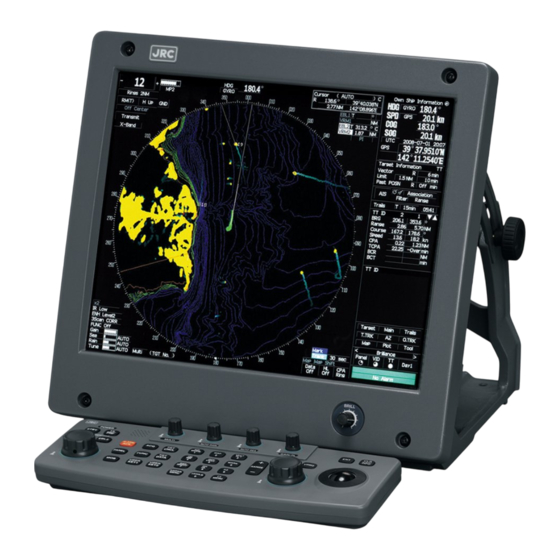
User image 681ef7ecc8b59

Subscribe to Our Youtube Channel

Summary of Contents for JRC JMA-5310-6

  • Page 1 JMA-5310-6 JMA-5320-7/9 JMA-5330-12 MARINE RADAR EQUIPMENT INSTRUCTION MANUAL...
  • Page 2: Precautions Before Operation

    ◆◆◆PRECAUTIONS BEFORE OPERATION◆◆◆ ■Cautions for high voltage High voltages from hundreds volts to tens of thousands volts are to be applied to the electronic equipment such radio and radar devices. You do not face any danger during normal operation, but sufficient cares are required for maintenance, inspection and adjustment of their internal components.
  • Page 3: First-Aid Treatments

      ◆◆◆FIRST-AID TREATMENTS◆◆◆  ☆First-aid treatments As far as the victim of electric shock is not in dangerous condition, do not move him and practice artificial respiration on him immediately. Once started, it should be continued rhythmically. (1) Do not touch the victim confusedly as a result of the accident, but the rescuer may also get an electric shock.
  • Page 4: When Pulse Is Beating But Breathing Has Stopped

    ☆When pulse is beating but breathing has stopped (Mouth-to-mouth respiration) Fig. 1 (1) Tilt the victim’s head back as far as this face looks back. (A pillow may be inserted his neck.) (2) Push his jaw upward to open his throat wide (to spread his airway). (3) Pinch the victim’s nostrils and take a deep breath, block his mouth completely with yours and blow into his mouth strongly.
  • Page 5: When Both Pulse And Breathing Have Stopped

      ☆When both pulse and breathing have stopped Perform the (Cardiac massage) Fig. 2 and (Mouth-to-mouth respiration) Fig. 1 When no pulse has come not to be felt, his pupils are open and no heartbeat is heard, cardiac arrest is supposed to have occurred and artificial respiration must be performed. (1) Place your both hands, one hand on the other, on the lower one third area of his breastbone and compress his breast with your elbows applying your weight on his breast so that it is dented about 2cm (Repeat compressing his breast 50 times or so a minutes).
  • Page 6: Preface

    PREFACE Thank you very much for purchasing the JRC marine radar equipment, JMA-5300 series. This equipment is a marine radar equipment designed to obtain safe operation of marine ships. This equipment consists of a radar signal transmitter-receiver unit, a LCD display unit and a scanner unit as its main units.
  • Page 7: Warning Label

      ●Before Operation● Pictorial Indication Various pictorial indications are included in this manual and are shown on these equipment so that you can operate them safety and correctly and prevent any danger to you and/or to other persons and any damage to your property during operation.
  • Page 8: Precautions

    ●PRECAUTIONS● DANGER Never conduct inspection or repair work of equipment components. Inspection or repair work by uncertified personnel may result in fire hazard or electrocution. For inspection and repair work of equipment components, consult with our branch office, branch shop, sales office, or our distributor in your district. When conducting maintenance, make sure to turn the main power off.
  • Page 9   DANGER Make sure to turn off the antenna operation switch. Failure to comply may result in injuries caused by physical contact with the rotating antenna. WARNING Never directly touch the internal components of the antenna, receiver/transceiver, or indicator. Direct contact with these high-voltage components may cause electrocution.
  • Page 10 WARNING About radiation from the antenna: Never stare at the antenna from a distance closer than that specified below for each type of antenna when it is emitting radiation. Being within the specified distance from the center of the front face of the antenna may cause radiation exposure which could result in injuries (especially of the eyes).
  • Page 11   WARNING When cleaning the display screen, do not wipe it too strongly with a dry cloth. Also, do not use gasoline or thinner to clean the screen. Failure to comply will result in damage to the screen surface. Do not change MBS Level/Area unless absolutely necessary.
  • Page 12 CAUTION Use ATA only as a navigation aid. The final navigation decision must always be made by the operator him/herself. Making the final navigation decision based only on ATA information may cause accidents. ARPA information such as vector, target numerical data, and alarms may contain some errors.
  • Page 13   CAUTION When setting a guard zone, make sure to properly adjust gain, sea-surface reflection suppression level, and rain/snow reflection suppression level so that the optimal target images are always on the radar screen. The guard zone alarm will not be activated for targets undetected by the radar, and it may result in accidents such as collisions.
  • Page 14 CAUTION Make sure to take off your watch when your hand must get close to the magnetron. Failure to comply may result in damage to the watch since the magnetron is a strong magnet. Make sure that two or more staff member work together when replacing the LCD.
  • Page 15   CAUTION Do not change the quantization level settings unless absolutely necessary. If set at an inappropriate value, the acquisition or tracking function of ARPA deteriorates, and this may lead to accidents. - x -...
  • Page 16: Equipment Appearance

    EQUIPMENT APPEARANCE Scanner Unit Type NKE-1075 (12 feet) Scanner Unit Type NKE-2102-6 (6 feet) Scanner Unit Type NKE-2252-7 (7 feet) - xi -...
  • Page 17   Scanner Unit Type NKE-2252-9 (9 feet) NDC-1273 Processor Unit (Desktop Type) NWZ-147 Display Unit (Desktop Type) NCE-7699 Operation Unit (Desktop Type) NCD-4510 Display Unit (Desktop Type) - xii -...
  • Page 18: Table Of Contents

    CONTENTS PREFACE........................i BEFORE OPERATION ................... ii PRECAUTIONS..................... iii EQUIPMENT APPEARANCE ................xi GLOSSARY......................xx 1. GENERAL AND EQUIPMENT COMPOSITION FUNCTIONS................... 1-1 1.1.1 FUNCTION OF THIS SYSTEM ............1-1 FEATURES..................... 1-2 CONFIGURATION .................. 1-4 EXTERIOR DRAWINGS................. 1-5 GENERAL SYSTEM DIAGRAMS ............1-14 2.
  • Page 19   3.3.1 ADJUST DISPLAY BRILLIANCE............3-8 3.3.2 ADJUST CONTRAST................3-8 3.3.3 ADJUST OPERATION PANEL BRILLIANCE [PANEL]......3-9 3.3.4 SWITCH DAY/NIGHT MODE [DAY/NIGHT] ........3-9 3.3.5 ADJUST BRILLIANCE OF INFORMATION ON RADAR DISPLAY (BRILLIANCE SETTING) ..............3-10 3.3.6 ADJUST SOUND VOLUME (BUZZER VOLUME) ......3-11 3.3.7 RESET ALARM BUZZER [ALARM ACK] ........
  • Page 20 CANCEL STORING OF OWN SHIP’S TRACK DATA (OWN TRACK MEMORY) .............. 3-70 DISPLAY CHARTS ................3-71 3.7.1 DISPLAY COASTLINE ROM CARD PRODUCED BY JRC .... 3-71 3.7.2 DISPLAY ERC CARD ..............3-72 3.7.3 FILL CHARTS (FILL LAND AREA) ..........3-73 DISPLAY NAVIGATION INFORMATION..........
  • Page 21   4. MEASUREMENT OF RANGE AND BEARING MEASUREMENT BY TRACKBALL ............4-1 MEASUREMENT BY RANGE RINGS.............4-2 MEASUREMENT BY EBLS AND VRMS ..........4-3 MEASUREMENT BETWEEN TWO OPTIONAL POINTS .......4-5 5. HOW TO USE ATA/ARPA PREPARATION ..................5-2 5.1.1 COLLISION AVOIDANCE ..............5-3 5.1.2 DEFINITIONS OF SYMBOLS ............5-6 5.1.3 SETTING COLLISION DECISION CRITERIA (CPA/TCPA LIMIT) ..5-8 5.1.4...
  • Page 22 5.4.5 SETTING AIS SYMBOL DISPLAY FUNCTION (AIS SYMBOL DISPLAY)..............5-56 5.4.6 DISPLAYING NUMERIC DATA OF AIS TARGETS......5-57 5.4.7 SETTING ATA/ARPA SYMBOL DISPLAY FUNCTION (ATA SYMBOL DISPLAY) ............... 5-59 5.4.8 SETTING AIS FILTER (AIS FILTER SETTING)......5-60 5.4.9 DECIDING AIS TARGET AND ARPA TARGET AS THE SAME ONE (IDENTICAL DISTANCE)..........
  • Page 23 DISPOSAL OF THE UNIT ..............10-1 10.2 DISPOSAL OF USED BATTERIES ............10-2 10.3 DISPOSAL OF USED MAGNETRON ...........10-3 11. SPECIFICATIONS 11.1 JMA-5310-6 TYPE RADAR ..............11-1 11.2 JMA-5320-7/9 TYPE RADAR ..............11-2 11.3 JMA-5330-12 TYPE RADAR ..............11-3 11.4 SCANNER (NKE-2102) ................. 11-4 11.5...
  • Page 24: Attached Drawing

    ATTACHED DRAWING 9 INTERNAL CONNECTION DIAGRAM OF DISPLAY UNIT, TYPE NCD-4510 ATTACHED DRAWING 10 INTERNAL CONNECTION DIAGRAM OF PROCESSOR UNIT, TYPE NCD-1273 ATTACHED DRAWING 11 INTERNAL CONNECTION DIAGRAM OF OPERATION UNIT, TYPE NCE-7699 ATTACHED DRAWING 12 INTERNAL CONNECTION DIAGRAM OF CONNECTION UNIT, TYPE NQE-3151 - xix -...
  • Page 25: Glossary

      GLOSSARY This section describes the main terms used for this equipment and general related maritime terms. ARPA: as scanned clockwise. Automatic Radar Plotting Aid. HL (Heading Line): AZI MODE (Azimuth Stabilization MODE): Ship’s heading line HUP (Head-Up): Bearing display mode Anti-clutter rain (FTC): Own ship’s heading line is always pointed to Rain/snow clutter suppression...
  • Page 26 SCANNER: TM (True Motion): Antenna True motion presentation A presentation in which own ship and any SEA: other target move depending on their Sea clutter suppression individual movements. SET: TRAILS: The current direction for manual correction Function of displaying tracks of other ships. or the current speed on the horizontal axis of TRAIL: the 2-axis log is displayed.
  • Page 27: Specification

      1 GENERAL AND EQUIPMENT COMPOSITION NAME AND FUNCTION OF CONTROL PANEL 2 SWITCHES AND FUNCTION OF SOFTWARE BUTTONS 3 BASIC OPERATION 4 MEASUREMENT OF RANGE AND BEARING 5 HOW TO USE ATA/ARPA 6 TRUE AND FALSE ECHOES ON DISPLAY 7...
  • Page 28: General And Equipment Composition

    SECTION 1 GENERAL AND EQUIPMENT COMPOSITION 1.1 Functions ......... 1 1.1.1 Function of This System ..1 1.2 Features ........... 2 1.3 Configuration........4 1.4 Exterior Drawings......5 1.5 General System Diagrams.... 14...
  • Page 29: Functions

    FUNCTIONS This equipment is a high-performance radar equipment consisting of a scanner unit, a transmitter-receiver unit and a high resolution color LCD display unit. 1.1.1 Function of This System The JMA-5300 series is a color radar system designed to comply with the international standards of the IMO.
  • Page 30: Features

    FEATURES Realization of Large, Easy-to-see Screen with High Resolution The 18.1-inch color LCD with high resolution of 1280 ´ 1024 pixels can display radar images of 250 mm or more in diameter. Even short-range targets can also be displayed as high-resolution images. Target Detection by Latest Signal Processing Technology The system employs the latest digital signal processing technology to eliminate undesired clutter from the radar video signals that are obtained from the receiver with a wide dynamic range, thus improving the target...
  • Page 31: Various Functions

    Improved Day/Night Mode Two types of background colors are available in each Day/Night mode (total 4 background colors). Each background color can be reproduced to be suited for the user’s operating environment by simple key operation. The radar echoes and a variety of graphics can also be represented in different colors, ensuring easy-to-see displays.
  • Page 32: Configuration

    CONFIGURATION Scanners and Transmitted Output Powers TRANSMITTED SCANNER TYPE BAND OUTPUT POWER JMA-5310-6 6 FT SLOT ANTENNA 10 KW JMA-5320-7 7 FT SLOT ANTENNA 25 KW JMA-5320-9 9 FT SLOT ANTENNA 25 KW JMA-5330-12 12 FT SLOT ANTENNA 30 KW Radar Configuration and Ship’s Mains...
  • Page 33: Exterior Drawings

    EXTERIOR DRAWINGS Fig. 1.1 Exterior Drawing of Scanner Unit, Type NKE-2102-6 Fig. 1.2 Exterior Drawing of Scanner Unit, Type NKE-2252-7 Fig. 1.3 Exterior Drawing of Scanner Unit, Type NKE-2252-9 Fig. 1.4 Exterior Drawing of Scanner Unit, Type NKE-1075 Fig. 1.5 Exterior Drawing of Display Unit, Type NWZ-147 Fig.
  • Page 34: Exterior Drawing

    1.4 EXTERIOR DRAWING Ÿ Fig. 1.1 Exterior Drawing of Scanner Unit, Type NKE-2102-6 1 - 6...
  • Page 35 Fig. 1.2 Exterior Drawing of Scanner Unit, Type NKE-2252-7 1 - 7...
  • Page 36 1.4 EXTERIOR DRAWING Ÿ Fig. 1.3 Exterior Drawing of Scanner Unit, Type NKE-2252-9 1 - 8...
  • Page 37 Fig. 1.4 Exterior Drawing of Scanner Unit, Type NKE-1075 1 - 9...
  • Page 38 1.4 EXTERIOR DRAWING Ÿ Fig. 1.5 Exterior Drawing of Display Unit, Type NWZ-147 1 - 10...
  • Page 39 Fig. 1.6 Exterior Drawing of Processing Unit, Type NDC-1273 1 - 11...
  • Page 40 1.4 EXTERIOR DRAWING Ÿ Fig. 1.7 Exterior Drawing of Operating Unit, Type NCE-7699 1 - 12...
  • Page 41 Fig. 1.8 Exterior Drawing of Connecting Unit, Type NQE-3151 1 - 13...
  • Page 42: General System Diagrams

    GENERAL SYSTEM DIAGRAMS Fig. 1.9 General System Diagram of Radar, Type JMA-5310-6 Fig. 1.10 General System Diagram of Radar, Type JMA-5320-7 Fig. 1.11 General System Diagram of Radar, Type JMA-5320-9 Fig. 1.12 General System Diagram of Radar, Type JMA-5330-12 1 - 14...
  • Page 43 NBA-3308 RECTIFIER (OPTION) NBA-3308 整 流器 ( オプシ ョン) Fig. 1.9 General System Diagram of Radar, Type JMA-5310-6 Note: Eliminating the interference on frequencies used for marine communications and navigation due to operation of the radar. All cables of the radar are to be run away from the cables of radio equipment.
  • Page 44: General System Diagrams

    250V-DPYCYS-1.25 (OPTION) (オ プショ ン) 250V-TTYCS-1 SHIP’S MAIN CFQ-6911 船内 電源 24 VDC 最大 径 φ10 (JRC支 給) 5m MAX f10 (JRC SUPPLY) DC24V 250V-DPYCYS-5.5 SHIP’S MAIN 船内 電源 AC100/110/115V 50/60Hz 1 φ 100/110/115 VAC 50/60HZ 1f AC200/220/230V 50/60Hz 1 φ...
  • Page 45 (OPTION) (オ プショ ン) 250V-TTYCS-1 SHIP’S MAIN CFQ-6911 船内 電源 24 VDC MAX f10 (JRC SUPPLY) 最大 径 φ10 (JRC支 給) 5m DC24V 250V-DPYCYS-5.5 SHIP’S MAIN 船内 電源 AC100/110/115V 50/60Hz 1 φ 100/110/115 VAC 50/60HZ 1f AC200/220/230V 50/60Hz 1 φ...
  • Page 46 250V-DPYCYS-1.25 (OPTION) (オ プショ ン) 250V-TTYCS-1 SHIP’S MAIN CFQ-6911 船内 電源 24 VDC 最大 径 φ10 (JRC支 給) 5m MAX f10 (JRC SUPPLY) 5M DC24V 250V-DPYCYS-5.5 SHIP’S MAIN 船内 電源 AC100/110/115V 50/60Hz 1 φ 100/110/115 VAC 50/60HZ 1f AC200/220/230V 50/60Hz 1 φ...
  • Page 48: Names And Functions Of Control Panel Switches And Functions Of Software Buttons

    SECTION 2 NAMES AND FUNCTIONS OF CONTROL PANEL SWITCHES AND FUNCTIONS OF SOFTWARE BUTTONS 2.1 NAMES AND FUNCTIONS OF CONTROL PANEL SWITCHES ...........1 2.2 FUNCTIONS OF SOFTWARE BUTTONS ..7...
  • Page 49: Names And Functions Of Control Panel Switches

    NAMES AND FUNCTIONS OF CONTROL PANEL SWITCHES Example of Display 2─1...
  • Page 50 2.1 NAMES AND FUNCTIONS OF CONTROL ŸŸ Names and Functions of Control Panel Switches The following page describe name of buttons. The Sections and page numbers on the above indicate pages where operation procedures and detailed descriptions are provided. 2─2...
  • Page 51 Trackball ① Use this trackball to move the cursor mark to an arbitrary point. The trackball can be used for setting in each mode. For example, use it to specify the center of a floating EBL or the off-center position. ®For setting cursor, see section 3.10.3 on page 3-102.
  • Page 52 2.1 NAMES AND FUNCTIONS OF CONTROL ŸŸ Use of this function with the interference reflector function heightens an interference suppressing effect. ®See section 3.4.1 on page 3-15. [EBL1] (Electric Bearing Line 1) Switch ⑩ Use this switch to display and select EBL1. Holding down the switch for two seconds or more displays the menu for EBL1 setting.
  • Page 53 [FUNC] (Function Call) Switch ⑱ Calls predefined signal processing setting when pressed. The selection changes in the following sequence each time the switch is pressed: ® ® ® ® ® Function Off Function 1 Function 2 Function 3 Function 4 Function Off Holding down the switch for two seconds or more displays the function setting menu.
  • Page 54 2.1 NAMES AND FUNCTIONS OF CONTROL ŸŸ [RR/HL] [8] (Fixed Range Marker/Heading Line Off/8) Switch The ship’s HL (heading line) is erased while this switch is held down. The fixed range marker display switches back and forth between display and non-display each time the switch is pressed.
  • Page 55: Functions Of Software Buttons

    FUNCTIONS OF SOFTWARE BUTTONS This radar provides the software buttons on the display which can be used to set several important functions directly and swiftly from the display without opening the corresponding menu. The names of buttons are described on the following pages. See the following pages. The Sections and page numbers on the above indicate pages where operation procedures and detailed descriptions are provided.
  • Page 56 2.1 NAMES AND FUNCTIONS OF CONTROL ŸŸ ①: Range selection Switches a radar range. “+”: Increments the range scale level by 1. (96 or 120 nm at maximum) “-”: Decrements the range scale level by 1. (0.125 nm at minimum) ®See section 3.4.3 on page 3-15.
  • Page 57 ⑩: Selection of radar interference reflector function Turns on/off the radar interference reflector function (IR). The selection changes in the following sequence each time the button is clicked. ® ® ® IR OFF IR LOW IR MEDIUM IR HIGH ®See section 3.4.8 on page 3-21. ⑪: Selection of radar video enhance function (ENH) Turns on/off the radar video enhance function.
  • Page 58 2.1 NAMES AND FUNCTIONS OF CONTROL ŸŸ ⑱: Multi-function Control Mode Each time you press this button, you can change the item registered in the multi-function control function. A switched item is displayed put in parentheses. Give a long press of the control to open the setup screen for registering items.
  • Page 59 : Selection of own ship’s track display function (TRACK) Turns on/off the own ship’s track display function, and enables the setting of track memory intervals. ®See section 3.6.1 on page 3-67. : Selection of map display position correction Turns on/off the map display position correction. The setup menu is open each time the button is pressed.
  • Page 60 2.1 NAMES AND FUNCTIONS OF CONTROL ŸŸ : Numeric data display mode of EBL1 Selects the numeric data display mode of EBL1 depending on the true or relative bearing. The selection changes each time the button is pressed. T is displayed while true bearing is selected; is displayed while relative bearing is selected.
  • Page 61: Radar Menu

    : SET/DRIFT Turns on/off the SET/DRIFT correction. If CORRECTION is on, CORR is displayed beside the button. In this case, the values shown to the right of CORR are valid. CORRECTION can be selected only when MANUAL or (1-axis log) is selected for the speed sensor. SET setting To enter a value, move the cursor to the value area and left-click.
  • Page 62: Display Info

    2.1 NAMES AND FUNCTIONS OF CONTROL ŸŸ : TEST menu Press this button to open the “TEST MENU” screen. Use this menu screen to operate the self-diagnostic function in the radar. : DISPLAY screen Press this button to display optional information such as navigation information. For the setting of information to be displayed, see section 3.10.4 on page 3-87.
  • Page 64: Basic Operation

    Adjust Sound Volume (Buzzer Volume) ........3-11 DISPLAY CHARTS..................3-71 3.3.7 Reset Alarm Buzzer [ALARM ACK]..........3-11 3.7.1 Display Coastline ROM Card Produced by JRC......3-71 3.3.8 Set Display Color ................3-12 3.7.2 Display ERC Card ................3-72 BASIC OPERATIONS ................. 3-15 3.7.3...
  • Page 65: Flow Operation

    FLOW OPERATION Attention l Do not put anything on the operation panel. If you put anything hot on it, it may be deformed. l Do not give any impact to the operation panel, trackball, or controls. Otherwise, any failure or damage may result. POWER ON AND START THE SYSTEM OBSERVE AND...
  • Page 66: Power On And Start The System

    Ÿ 3.1 FLOW OPERATION Ÿ Ÿ 3.1.1 Power ON and Start the System Caution A malfunction may occur if the power in the ship is instantaneously interrupted during operation of the radar. In this case, the power should be turned on again. Attention l Wait for about 2 seconds before turning on the power again.
  • Page 67: Observe And Adjust Video

    Procedures Check that the ship’s mains are turned on. Press [STBY] key. The system is turned on, and the preheating time is displayed. PREHEAT is indicated at the upper left of the radar display. Wait until the preheating time is over. When the preheating time is over, the preheating time screen disappears, and PREHEAT at the upper left of the radar display changes to...
  • Page 68: End The Operation And Stop The System

    Ÿ 3.1 FLOW OPERATION Ÿ Ÿ 3.1.4 End the Operation and Stop the System Exit Press [STBY] key. The radar will stop transmission and the antenna will stop rotating. TRANSMIT at the upper left of the radar display changes to STANDBY .
  • Page 69: Menu Composition

    MENU COMPOSITION The Menu system of this radar equipment consists of the main menu and the submenus up to the lower 2 levels. You can jump to each menu by pressing the menu button at the lower right of the radar display or the switch on the operation panel.
  • Page 70: Basic Menu Operation

    Ÿ 3.2 MENU COMPOSITION Ÿ Ÿ 3.2.2 Basic Menu Operation To open the menu: Press [RADAR MENU] key. To close the menu: Press [RADAR MENU] key. Alternatively, hold down [0] key until the menu closes. * Button on the radar display on page 2-7 is also available to switch between ON and OFF. To move to a lower level of the menu: The menu is in hierarchical structure.
  • Page 71 Menu Operation with the Trackball The menu items are software buttons that can be operated with the trackball. An item can be selected by pointing the trackball cursor to the item and pressing [ENT] key, instead of using the numeric key. Example of menu display The selected item is Process Setting...
  • Page 72: Preparation

    PREPARATION 3.3.1 Adjust Display Brilliance Procedures Obtain the best-to-see display with optimum brilliance by turning the [BRILL] control at the lower right of the display. Turning the [BRILL] control clockwise increases the brilliance of the entire display. Conversely, turning the [BRILL] control counterclockwise decreases the brilliance of the entire display.
  • Page 73: Adjust Operation Panel Brilliance [Panel]

    3.3.3 Adjust Operation Panel Brilliance [PANEL] Procedures Press [PANEL] key to adjust the brilliance of the operation panel light. There are five brilliance levels, and brilliance increases by one level each time the [PANEL] key is pressed. When it reaches the highest level, it is resumed to the lowest level.
  • Page 74: Adjust Brilliance Of Information On Radar Display (Brilliance Setting)

    Ÿ 3.3 PREPARATION Ÿ Ÿ 3.3.5 Adjust Brilliance of Information on Radar Display (Brilliance Setting) Brilliance can be adjusted for each item of information on the radar display by operating the menu. RADAR Video Adjusts the brilliance of radar echoes. RADAR Trails Adjusts the brilliance of radar trails.
  • Page 75: Adjust Sound Volume (Buzzer Volume)

    3.3.6 Adjust Sound Volume (Buzzer Volume) Procedures Press [RADAR MENU] key twice. RADAR Sub Menu 1. PIN Setting Press [8] key. The RADAR Sub Menu will appear. 2. Multi Dial Setting Press [5] key to select Buzzer Volume. 3. User Key Setting The pull-down menu will appear showing the volume levels.
  • Page 76: Set Display Color

    Ÿ 3.3 PREPARATION Ÿ Ÿ 3.3.8 Set Display Color For each day/night mode, set the colors of the background outside the bearing scale, the background inside the bearing scale, characters, radar echoes, and radar trails. Color Adjustment by Menu Operation Day/Night Registers the switching of a day/night mode.
  • Page 77 Calling of a Color Scheme (Color Scheme) Call a preset color scheme pattern. Procedures Press [2] key while the Display Color Display Color Setting Setting Menu is open. 1. Day/Night The Color Scheme Menu will appear. DAY1 2. Color Scheme Select the pattern number to be set, pressing the numeric keys [1] to [6].
  • Page 78 Ÿ 3.3 PREPARATION Ÿ Ÿ Setting Colors of Items Set the display color of each item. Procedures While the Display Color Setting Menu Display Color Setting is open, select the item number for 1. Day /Night color setting, pressing the numeric keys [3] to [8].
  • Page 79: Basic Operations

    BASIC OPERATIONS 3.4.1 Start Transmission [TX/PRF] Procedures Press [TX/PRF] key. The radar will start transmission and the antenna will start rotating. The indication STANDBY at the upper left of the radar display changes to TRANSMIT . Note: The radar does not start transmission if you press [TX/PRF] key while PREHEAT indicated.
  • Page 80: Tune

    Ÿ 3.4 BASIC OPERATIONS Ÿ Ÿ 3.4.4 Tune This system tunes the transmitting frequency and receiving frequency under automatic control, so it does not need any tuning by hand 3.4.5 Control Sensitivity [GAIN/PL] Procedures Control noise on the radar display by turning the [GAIN/PL] control until targets can be easily observed.
  • Page 81: Suppress Sea Clutter [Auto-Sea]

    3.4.6 Suppress Sea Clutter [AUTO-SEA] Caution When using the [AUTO SEA] function, never set the suppression level too high canceling out all image noises from the sea surface at close range. Detection of not only echoes from waves but also targets such as other ships or dangerous objects will become inhibited.
  • Page 82 Ÿ 3.4 BASIC OPERATIONS Ÿ Ÿ Note: When AUTO SEA is selected, AUTO RAIN is switched to the manual mode. AUTO SEA and AUTO RAIN cannot be selected at the same time. Cancellation Press the [AUTO-SEA] control. AUTO SEA is deselected, SEA AUTO at the lower left of the radar display changes to SEA MAN , and AUTO SEA is cancelled.
  • Page 83: Suppress Rain/Snow Clutter [Auto-Rain]

    3.4.7 Suppress Rain/Snow Clutter [AUTO-RAIN] Caution When using the [AUTO RAIN] function, never set the suppression level too high canceling out all image noises from the rain or snow at the close range. Detection of not only echoes from the rain or snow but also targets such as other ships or dangerous objects will become inhibited.
  • Page 84 Ÿ 3.4 BASIC OPERATIONS Ÿ Ÿ Note: When AUTO RAIN is selected, AUTO SEA is switched to the manual mode. AUTO SEA and AUTO RAIN cannot be selected at the same time. Cancellation Press the [AUTO-RAIN] control. AUTO RAIN is deselected, RAIN AUTO at the lower left of the radar display changes to RAIN MAN , and AUTO RAIN is cancelled.
  • Page 85: Reject Radar Interference [Ir]

    3.4.8 Reject Radar Interference [IR] Procedures Press [RADAR MENU] key. Main Menu 1. IR The Main Menu will appear. IR OFF Press [1] key. 2. PROCES IR OFF IR LOW PROC OFF The IR Menu will appear. IR MEDIUM 3. TARGET ENHANCE Select the level number to be set, IR HIGH pressing the numeric keys [1] to [4].
  • Page 86: Hide/Display Range Rings (Rings)

    Ÿ 3.4 BASIC OPERATIONS Ÿ Ÿ 3.4.9 Hide/Display Range Rings (RINGS) Procedures Press [RR/HL] key. The range rings display switches back and forth between display and non-display each time [RR/HL] key is pressed. Refer to page 3-10 for how to change the brilliance of range rings. * Button on the radar display on page 2-7 is also available to switch between ON and OFF.
  • Page 87: Hide Graphics Information On Radar Display (Graphic Display)

    3.4.11 Hide Graphics Information on Radar Display (Graphic Display) Main Menu Procedures Press [RADAR MENU] key. 1. IR The Main Menu will appear. IR OFF Press [8] key. 2. Process PROC OFF The setting of Graphic Display will be changed 3.
  • Page 88: General Operations

    GENERAL OPERATIONS 3.5.1 Move Cross Cursor Mark by Trackball The cross cursor mark is used for position designation and other purposes in various operating procedures. The cross cursor mark moves in coupling with the trackball. If the trackball is rotated up and down or right and left, the cross cursor mark follows the move of the trackball.
  • Page 89: Use Ebls (Electronic Bearing Lines) [Ebl1/2]

    3.5.2 Use EBLs (Electronic Bearing Lines) [EBL1/2] EBLs (Electronic Bearing Lines) are indispensable to the measurement of bearings. Operators must be familiar with the operation of EBLs beforehand. EBL1 Operation If EBL2 is selected or EBL1 is not displayed, press [EBL1] key to select EBL1 before starting operation. (The currently selected EBL is shown in reverse video at the lower right of the radar display.) Procedures Press [EBL1] key.
  • Page 90 Ÿ 3.5 BASIC OPERATIONS Ÿ Ÿ EBL Bearing Display The bearing values of EBL1 and EBL2 currently displayed on the PPI are indicated at the lower right of the radar display. The currently operable EBL1 or EBL2 is shown in reverse video beside the bearing value. Starting Point of EBL The starting point of the currently operating EBL can be switched from the center of the radar display (CENTER) to any offset position (OFFSET).
  • Page 91: Set Ebl Operation (Ebl1 /2 Setting)

    3.5.3 Set EBL Operation (EBL1 /2 Setting) Setting the bearing display mode of EBL1 (EBL1 Bearing REF) Determine whether to display EBLs (Electronic Bearing Lines) in true bearing mode or relative bearing mode. Procedures Press [RADAR MENU] key twice. EBL1 Setting 1.
  • Page 92 Ÿ 3.5 BASIC OPERATIONS Ÿ Ÿ [III] Setting the mode to move the starting point of EBL1 (EBL1 Floating) When this function is set to L/L FIX and the starting point of an EBL is moved to a position, the starting point can be fixed at the latitude and longitude of that position.
  • Page 93 [V] Setting the EBL1 bearing fix mode (EBL1 Bearing FIX) While this function is set to ANGLE , an EBL is fixed to the preset bearing. For example, if the true bearing 020° is preset, the EBL is fixed to the true bearing 020° even when the own ship turns. While the function is set to SCREEN , the EBL is fixed on the radar display.
  • Page 94: Display Variable Range Markers [Vrm1/Vrm2]

    Ÿ 3.5 BASIC OPERATIONS Ÿ Ÿ 3.5.4 Display Variable Range Markers [VRM1/VRM2] This function is to display and select variable range markers (VRMs). Two VRMs are available: VRM1 is represented as a broken line, and VRM2 as a dotted line. When EBL1 is displayed, VRM1 marker appears on the EBL1.
  • Page 95 VRM2 Operation If VRM1 is selected or VRM2 is not displayed, press [VRM2] key to select VRM2 before starting operation. (The currently selected VRM is shown in reverse video at the lower right of the radar display.) Procedures Press [VRM2] key. VRM2 at the lower right of the radar display will be shown in reverse video, and VRM2 becomes operable.
  • Page 96 Ÿ 3.5 BASIC OPERATIONS Ÿ Ÿ Units of VRM2 range display (VRM 2Range Unit) Procedures Press [RADAR MENU] key twice. Marker Setting 1. EBL1 Setting Press [3] key. The Marker Setting Menu will appear. 2. EBL2 Setting Press [4] key. 3.
  • Page 97: Display Parallel Index Lines (Parallel Index Line)

    3.5.5 Display Parallel Index Lines (Parallel Index Line) Parallel index lines can be displayed. Procedures Press the [VRM] control. Parallel Index Line 1. Display Parallel index lines and the PI Individual Menu will appear. To change the direction of parallel index lines, 2.
  • Page 98 Ÿ 3.5 BASIC OPERATIONS Ÿ Ÿ Operation of Parallel Index Lines ◎ Parallel index lines rotate in the same direction as you turn the [EBL] control. (①, ②) ◎ The intervals of parallel index lines narrow when you turn the [VRM] control counterclockwise (③), and widen when you turn the [VRM] control clockwise (④).
  • Page 99 Setting of Parallel Index Lines (Parallel Index Line) [I] Parallel Index Line Display (Display) In the radar menu, you can switch parallel index line display between ON and OFF. Procedures Press [RADAR MENU] key twice. Parallel Index Line Press [3] key. 1.
  • Page 100 Ÿ 3.5 BASIC OPERATIONS Ÿ Ÿ [II] Parallel Index Line Range Link (Range Link) When range of parallel index lines is switched between ON and OFF, the range link is displayed. Procedures Press [RADAR MENU] key twice. Parallel Index Line Press [3] key.
  • Page 101 [III] Parallel Index Line Bearing (PI Bearing REF) Parallel index line bearing mode can be switched. Procedures Press [RADAR MENU] key twice. Parallel Index Line 1. Display Press [3] key. Press [5] key. 2. Range Link The Parallel Index Line Menu will appear. 3.
  • Page 102 Ÿ 3.5 BASIC OPERATIONS Ÿ Ÿ [IV] Parallel Index Line Start Point Display Mode (PI Floating) If this function is set to L/L FIX, and the start point of parallel index line moves, the start point of the parallel index line can be fixed to the latitude/longitude of the start point. If the function is set to SCREEN FIX, the start point of parallel index line is fixed within the radar display, and the start point is fixed to the same place on the display even after the own ship moves.
  • Page 103 [V] Parallel Index Line Bearing Fix Mode (PI Bearing Fix) If this function is set to ANGLE , the parallel index line also rotates in accordance with the bearing while the own ship is turning. If the function is set to SCREEN FIX , the parallel index lines are fixed within the radar display even while the own ship is turning.
  • Page 104 Ÿ 3.5 BASIC OPERATIONS Ÿ Ÿ [VI] Individual Display of Parallel Index Line (PI Individual) Individual parallel index lines can be switched between ON and OFF. Procedures Press [RADAR MENU] key twice. PI Individual 1. Line 1 Press [3] key. Press [5] key.
  • Page 105: Switch Bearing Display Mode [Azi Mode]

    3.5.6 Switch Bearing Display Mode [AZI MODE] The bearing display mode is switched in the sequence of [NORTH UP] (true bearing), [HEAD UP] (relative bearing), and [COURSE UP] (course-up bearing) each time [AZI MODE] key is pressed. HUP ® NUP ® The indication at the upper left of the radar display changes in sequence of CUP .
  • Page 106: Switch True/Relative Motion Display Mode [Tm/Rm]

    Ÿ 3.5 BASIC OPERATIONS Ÿ Ÿ 3.5.7 Switch True/Relative Motion Display Mode [TM/RM] Switching Relative Motion (RM) Mode to True Motion (TM) Mode Procedures Press [TM/RM] key. The true motion mode will be selected. In the true motion mode, the own ship’s position on the radar display moves depending upon its speed and course and the influence of the current.
  • Page 107: Move Own Ship's Display Position [Off Cent]

    3.5.8 Move Own Ship’s Display Position [OFF CENT] The own ship’s position can be moved from the display center to any position within 66% of the display radius. This function is convenient for observing a wide coverage in any direction. Note: This function is not available on the 96 NM range.
  • Page 108: Display Other Ships' Trails [Trails]

    Ÿ 3.5 BASIC OPERATIONS Ÿ Ÿ 3.5.9 Display Other Ships’ Trails [TRAILS] Other ships’ movements and speeds can be monitored from the lengths and directions of their trails, serving for collision avoidance. The trail length varies according to setting. The setting is described on the next page. Procedures Trail length setting in SHORT mode: Press [TRAILS] key.
  • Page 109: Trails Motion Mode

    SHORT mode: 15 sec, 30 sec, 1 min, 3 min, 6 min, 10 min, 15 min, and CONT MID mode: 30 sec, 1 min, 3 min, 6 min, 10 min, 15 min, 30 min, and CONT LONG mode: 1 min, 3 min, 6 min, 10 min, 15 min, 30 min, 60 min, and CONT SUPER LONG mode: 30 min, 1 hr, 2 hr, 3 hr, 4 hr, 5 hr, 6 hr, 7 hr, 8 hr, 9 hr, 10 hr, 11 hr, 12 hr and CONT...
  • Page 110 Ÿ 3.5 BASIC OPERATIONS Ÿ Ÿ Trails modes provided with this system vary depending on the motion mode. With true motion (TM) mode: Only the true motion trails mode is available. With relative motion (RM) mode: The relative motion trails mode or true motion trails mode is selectable.
  • Page 111: Switch Pulse Length (Gain/Pl)

    3.5.10 Switch Pulse Length (GAIN/PL) Procedures Press [GAIN/PL] key. The transmitter pulse length changes cyclically in the following sequence each time [GAIN/PL] key is pressed: SP ® MP ® LP ® The currently selected pulse length is indicated at the upper left of the radar screen. The pulse length can be changed only when the range is set to 0.75, 1.5, 3, 6, or 12 NM.
  • Page 112: Expand Targets (Target Enhance)

    Ÿ 3.5 BASIC OPERATIONS Ÿ Ÿ 3.5.11 Expand Targets (Target Enhance) This function expands targets shown on the radar display. Procedures Press [RADAR MENU] key. Main Menu 1. IR The Main Menu will appear. IR OFF Press [3] key. 2. Process PROC OFF The Target Enhance Selection Menu will 3.
  • Page 113: Use Video Process (Process)

    3.5.12 Use Video Process (Process) This function reduces unnecessary noise to highlight targets. Attention l When viewing a radar beacon, SART signal, or fast moving target on the radar display, select PROCESS OFF (video process off). Main Menu Procedures Press [RADAR MENU] key. 1.
  • Page 114: Zoom

    Ÿ 3.5 BASIC OPERATIONS Ÿ Ÿ 3.5.13 Zoom This function doubles the size of radar video near a specified position. Attention If the range is 0.125 NM, this function is not available. Procedures Press [RADAR MENU] key. Main Menu 1. IR The Main Menu will appear.
  • Page 115: Use Marker [Mob]

    3.5.14 Use Marker [MOB] The marker function displays a dotted line from the marker input position to the own ship’s position, and indicates the range, bearing, and required time from the own ship to the marker. Procedures Press [MOB] key. A marker will be displayed at the own ship’s position on the radar display at the moment when [MOB] key is pressed.
  • Page 116: Marking [Mark]

    Ÿ 3.5 BASIC OPERATIONS Ÿ Ÿ 3.5.15 Marking [MARK] A maximum of 20 marks can be indicated at arbitrary positions on the radar display. A mark created on the radar display holds the latitude and longitude. [I] Creating Marks Procedures Press [MARK] key.
  • Page 117: Operate Ebl Maneuver Function (Ebl Maneuver)

    3.5.16 Operate EBL Maneuver Function (EBL Maneuver) [I] Initial Setting (Reach,Turn Mode, Turn Set) Procedures Press [RADAR MENU] key twice. EBL Maneuver Press [3] key. 1. EBL Maneuver Press [7] key. 2. Reach 1000 m The EBL Maneuver Menu will appear. 3.
  • Page 118 Ÿ 3.5 BASIC OPERATIONS Ÿ Ÿ [II] Creating Maneuver Curve (EBL Maneuver) Procedures Press [1] key while the EBL Maneuver menu is open. EBL Maneuver will be set to ON. A supplemental line, a maneuver curve, and WOL will appear on the radar display. Set the starting point of the supplemental line using the trackball, and set the bearing of the supplemental line using the [EBL] control.
  • Page 119 Cancellation Press [1] key. The EBL Maneuver function will be set to OFF. Exit Press [RADAR MENU] key. The EBL Maneuver Menu will close. Supplemental line Maneuver curve Own ship’s position Scheduled route WOL: Steering point REACH: Distance from when the wheel is steered to when the ship begins to turn Turning radius 3─55...
  • Page 120: Operate Multi-Function Control [Multi]

    Ÿ 3.5 BASIC OPERATIONS Ÿ Ÿ 3.5.17 Operate Multi-Function Control [MULTI] The multi-function control [MULTI] is provided to change the settings of parameters such as the length of radar trails. Turn the control to select a parameter. Radar operation is simplified by using the control. [I] Initial Setting (Multi Dial Setting) Set parameters that can be operated with the multi-function control.
  • Page 121 [II] Using Multi-function Control Procedures Press the [MULTI] control to select the parameter whose setting is to be changed. Parameters will be selected sequentially each time the [MULTI] control is pressed. The currently selected parameter is indicated at the lower right of the radar display. For example, if three parameter 1-3 are initially set to ON , they are selected in the following sequence each time the [MULTI] control is pressed:...
  • Page 122: Operate User Key Switches [User Key 1/2]

    Ÿ 3.5 BASIC OPERATIONS Ÿ Ÿ 3.5.18 Operate User Key Switches [User Key 1/2] Users can freely make settings with [USER KEY1] key and [USER KEY2] key. By using the switches, users can open a frequently used menu by only single operation, or assign special functions, which are not on the standard operation panel, to the user key switches.
  • Page 123 [II] Using User Key Switches (Directly displaying a specified menu) Preset the menu that is to be displayed with the user key switch. Setting the menu that is to be displayed with User Key 1: Procedures Perform the general menu open procedure to open the menu that is to be directly displayed with User Key 1.
  • Page 124: Operation Of Guard Zone [Ata Guard Zone]

    Ÿ 3.5 BASIC OPERATIONS Ÿ Ÿ 3.5.19 Operation of Guard Zone [ATA Guard Zone] A fan-shaped guard zone can be set to watch for other ships and targets to invade or to automatically track other invading ships. The guard zone function can be switched between ON and OFF by placing the cursor on on the radar display on page 2-7 and pressing [ENT].
  • Page 125 Start point: Determined by the first [ENT] End point: Determined by the second [ENT] Guard zone Attention Guard zones 1 and 2 can be set in the range of 0.5 to 32 nm. The width of distance of the guard zone is fixed to 0.5 nm. Operation of Guard zone ·...
  • Page 126 Ÿ 3.5 BASIC OPERATIONS Ÿ Ÿ [II] Set [GZALARM] key (Set GZ Alarm key) Set a guard zone that is turned ON/OFF when the [OZ ALARM] key is pressed. Such a guard zone can be simply called by assigning this key to a guard zone to be used on a steady basis.
  • Page 127: Radar Alarm (Radar Alarm)

    3.5.20 Radar Alarm (Radar Alarm) With a fan-shaped range made, the radar alarm can give an alarm to ships that invade or depart from the range. [I] Set Radar Alarm Mode (Radar Alarm Mode) For alarm issuing conditions for the radar alarm, set either entry or departure. Procedures Press [ATA MENU] key.
  • Page 128 Ÿ 3.5 BASIC OPERATIONS Ÿ Ÿ [II] Set Radar Alarm Detection Level (Sensitivity Level) Detection levels can be set to issue alarms from the radar alarm. Procedures Press [ATA MENU] key. RADAR Alarm 1. Sector RADAR Alarm > The ATA Menu will appear. Press [4] key.
  • Page 129 [III] Make Sector Alarm (Make Sector Alarm) Sector alarms that can be made are divided into the two types. Procedures Press [ATA MENU] key. Make Sctor Alarm The ATA Menu will appear. 1. Sector Alarm 1 Press [4] key. 2. Sector Alarm 2 Press [2] key.
  • Page 130 Ÿ 3.5 BASIC OPERATIONS Ÿ Ÿ [IV] Display Sector Alarm (Sector Alarm 1, 2) Display a created Sector Alarm. Procedures Press [ATA MENU] key. Sector RADAR Alarm The ATA Menu will appear. 1. Sector Alarm 1 Press [4] key. 2. Sector Alarm 2 Press [2] key.
  • Page 131: Display Own Ship's Track

    DISPLAY OWN SHIP’S TRACK 3.6.1 Display Own Ship’s Track (Display Own Track) If navigation equipment is connected, this system records data received from the navigation equipment and displays the own ship’s track. Procedures Press [RADAR MENU] key twice. Own Track Setting 1.
  • Page 132: Set Own Ship's Track Data Storage Interval (Own Track Interval)

    Ÿ 3.6 DISPLAY OWN SHIP’S TRACK Ÿ Ÿ 3.6.2 Set Own Ship’s Track Data Storage Interval (Own Track Interval) There are 10 preset time intervals and 4 preset range intervals that can be selected for storing own ship’s track data. Own Track Setting Procedures Press [RADAR MENU] key twice.
  • Page 133: Clear Own Ship's Track Data (Clear Own Track)

    3.6.3 Clear Own Ship’s Track Data (Clear Own Track) This function clears own ship’s track data from memory. Procedures Press [RADAR MENU] key twice. Own Track Setting 1. Own Track Interval Press [9] key. 1 min Press [1] key. 2. Display Own Track The Own Track Setting mMenu will appear.
  • Page 134: Cancel Storing Of Own Ship's Track Data (Own Track Memory)

    Ÿ 3.6 DISPLAY OWN SHIP’S TRACK Ÿ Ÿ 3.6.4 Cancel Storing of Own Ship’s Track Data (Own Track Memory) This function cancels the storing of own ship’s track data. Procedures Press [RADAR MENU] key twice. Own Track Setting 1. Own Track Interval Press [9] key.
  • Page 135: Display Charts

    3.7.1 Display Coastline ROM Card Produced by JRC l Make sure of the top surface of the Coastline ROM card produced by JRC, and insert the card with the top surface upward into card slot 1 (lower) or 2 (upper) as shown in the figure below. The coastlines will be displayed automatically.
  • Page 136: Display Erc Card

    For ranges of charts to be displayed, refer to the catalog issued by Japan Hydrographic Association. l Do not insert JRC’s Coastline ROM card or C-MAP card into a card slot while the ERC card is in the other slot. Doing so causes display trouble.
  • Page 137: Fill Charts (Fill Land Area)

    3.7.3 Fill Charts (Fill Land Area) This function fills the chart when JRC/ERC card is in use. Procedures Press [RADAR MENU] key twice. Map Setting 1. Fill Land Area Press [9] key. Press [5] key. 2. C-MAP Setting The Map Setting Menu will appear.
  • Page 138: Display Navigation Information

    DISPLAY NAVIGATION INFORMATION Navigation information such as waypoint marks, and a maximum of 256 points of NAV lines, coastlines, depth contours, and NAV marks can be displayed, created, read, saved, corrected, and deleted. (This function is available only when navigation equipment is connected with the system.) 3.8.1 Display Waypoint Marks (Waypoint Display) When waypoint information is received from the navigation equipment, the waypoint mark appears on the radar display.
  • Page 139: Display Navigation Information (Nav Display Setting)3-75

    3.8.2 Display Navigation Information (NAV Display Setting) The navigation information below can be displayed (ON) or hidden (OFF) individually.  NAV lines [NAV Line] ― ---- ‚ Coastlines [Coast Line] ƒ Depth contours [Contour] ‐― „ Mark 1 [Mark 1] …...
  • Page 140: Create/Edit Navigation Information (Edit User Map)

    Ÿ 3.8 DISPLAY NAVIGATION INFORMATION Ÿ Ÿ 3.8.3 Create/Edit Navigation Information (Edit User Map) Procedures Press [RADAR MENU] key. Edit User Map Press [6] key. 1. Clear Map Object > Press [3] key. 2. Make Map Object > Press [6] key. 3.
  • Page 141 1 Clearing all or an item of navigation information (Clear Map Object) Procedures Press [1] key while the Edit User MAP Clear Map Object Menu is open. 1. NAV Line ― The Clear Map Object Menu will appear. 2. Coast Line ---- Select the type of navigation information to be cleared, pressing the corresponding numeric key.
  • Page 142 Ÿ 3.8 DISPLAY NAVIGATION INFORMATION Ÿ Ÿ 2 Making navigation information (Make Map Object) Procedures Press [2] key while the Edit User MAP Make Map Object Menu is open. 1. NAV Line ― The Make Map Object Menu will appear. 2.
  • Page 143 3 Correcting a continuous line or moving a mark (Correct) Procedures Press [3] key while the Edit User Map Menu is open. The navigation information correction mode will be activated. Correct will appear in the CURSOR mode field at the radar display button Use the trackball to move the pointer to the vertex in a line to be corrected or the mark to be moved, and press [ENT] key.
  • Page 144 Ÿ 3.8 DISPLAY NAVIGATION INFORMATION Ÿ Ÿ 4 Deleting a continuous line or mark (Delete) Procedures Press [4] key while the Edit User Map Menu is open. The navigation information deletion mode will be activated. Delete will appear in the CURSOR mode field at the radar display button Use the trackball to move the pointer to the vertex in a line or the mark...
  • Page 145 5 Inserting a vertex into a line (Insert) Procedures Press [5] key while the Edit User MAP Menu is open. The navigation information insertion mode will be activated. Insert will appear in the CURSOR mode field at the radar display button Use the trackball to move the pointer to the line that is to become a vertex, and press [ENT] key.
  • Page 146: Set Navigation Information (User Map Setting)

    Ÿ 3.8 DISPLAY NAVIGATION INFORMATION Ÿ Ÿ 3.8.4 Set Navigation Information (User Map Setting) Procedures Press [RADAR MENU] key. User Map Setting 1. Own Ship Position Press [6] key. N 35°23.000’ Press [3] key. E139°22.345’ The User Map Setting Menu will appear. 2.
  • Page 147 [I] Entering the own ship’s position in manual mode (Own Ship Position) Use this function to edit the navigation information of any positions other than the own ship’s position. Procedures Press [1] key while the User Map Setting Menu is open. The CODE INPUT Menu for entering latitude and longitude of the own ship position will appear.
  • Page 148 Ÿ 3.8 DISPLAY NAVIGATION INFORMATION Ÿ Ÿ [II] Loading navigation information (Load User Map) Procedures Press [2] key while the User Map Load User Map Setting Menu is open. 1. Device The Load User Map Menu will appear. INTERNAL 2. Load User MAP >...
  • Page 149 [III] Initializing Navigation Information (Unload) Procedures When the User MAP Setting Menu User MAP Setting appears, press [3] key. 1. Own Ship Position Display the window to select whether or not the 35°23.000’ N information is to be initialized. 139°22.345’ E Press [1] key.
  • Page 150 Ÿ 3.8 DISPLAY NAVIGATION INFORMATION Ÿ Ÿ [IV] Saving navigation information (Save User Map) This function is available only when navigation equipment is connected with the system or the own ship’s position is entered in manual mode. Save User Map Procedures Press [4] key while the User Map 1.
  • Page 151 [V] Erasing navigation information from memory (Erase User Map) Procedures Press [5] key while the User Map Erase User Map Setting Menu is open. 1. Device INTERNAL Press [2] key. 2. Erase User MAP > The Erase User Map Menu will appear. * Each time you press [1] key, the Device item is switched between INTERNAL and CARD2.
  • Page 152 Ÿ 3.8 DISPLAY NAVIGATION INFORMATION Ÿ Ÿ [VII] Shifting the display position of navigation information to a correct position (Shift) If the display position of navigation information is incorrect, it can be shifted to the correct position in manual mode. Procedures Press [7] key while the User Map Setting Menu is open.
  • Page 153: Set And Display Geodetic System

    3.8.5 Set and Display Geodetic System To create navigation information, set the geodetic system that is used with the connected navigation equipment. When navigation information is loaded, the geodetic system, used when the navigation information was saved, is displayed. Make sure that the displayed geodetic system is identical to the one used with the navigation equipment.
  • Page 154 Ÿ 3.8 DISPLAY NAVIGATION INFORMATION Ÿ Ÿ Geodetic System List Name WGS-84 WGS-72 Japan North American 1927(U.S) North American 1927(Canada & Alaska) European 1950 (Europe) Australian geodetic 1966 (Australia) Ordance Survery of Great Britain (England) NAD-83 - (No Use) - (No Use) ADINDAN (Etiopia &...
  • Page 155: Operate Performance Monitor (Pm Display)

    OPERATE PERFORMANCE MONITOR (PM DISPLAY) 3.9.1 Operation Procedures This function is available only when the radar equipment is equipped with the NJU-63/64 Performance Monitor. 1 Preparation for Operation If the equipment is provided with a radar interswitch, set the interswitch to the Master Radar mode. Procedures Press [RADAR MENU] key twice.
  • Page 156 Ÿ 3.9 OPERATE PERFORMANCE MONITOR Ÿ Ÿ PM pattern 2 Checking Transmitter System TX LVL indicator bar-graph in the menu indicates the value corresponding to the transmitted power. If the currently indicated bar is extremely shorter than when initially checked, the transmitter system needs to be inspected by the service engineer.
  • Page 157: Check Procedure

    Check Procedure  Read the value A of the current bar length. ‚ Referring to the Calibration Curve I, obtain the relative attenuation d (B) for the initial bar length B shown on the INFORMATION LABEL. ƒ Referring to the Calibration Curve I, obtain the relative attenuation d (A) for the value A.
  • Page 158 Ÿ 3.9 OPERATE PERFORMANCE MONITOR Ÿ Ÿ (Example) When the initial bar length B = 8 and the current bar length A = 6, the relative attenuation is obtained as d (B) = 3.5 dB and d (A) = 7 dB according to the Calibration Curve I. Thus, d (A) - d (B) = 3.5 dB.
  • Page 159 3 Checking Receiver System The maximum range of the PM pattern on the display indicates that the receiver system’s sensitivity has reduced. Check Procedure  Measure the maximum range rmax from the PPI center to the PM pattern on the display by using a VRM (Variable Range Marker).
  • Page 160 Ÿ 3.9 OPERATE PERFORMANCE MONITOR Ÿ Ÿ (Example) When the maximum range of the initial PM pattern rBmax = 18 NM as shown on the INFORMATION LABEL and the maximum range of the current PM pattern rAmax = 16 NM, the reduction of sensitivity DR (rmax) = 5 dB is obtained according to the Calibration Curve II.
  • Page 161: Applied Operations

    3.10 APPLIED OPERATIONS 3.10.1 Set Radar Signal Processing (Process Setting) This function enables the setting of detail information about radar signal processing. Procedures Press [RADAR MENU] key twice. Process Setting 1. Video Latitude Press [1] key. NORMAL The Process Setting Menu will appear. 2.
  • Page 162 Ÿ 3.10 APPLIED OPERATIONS Ÿ Ÿ [2] Video Noise Rejection · This function rejects signals that assumed as noise and clutter in radar videos. · Select to display radar videos like analog signals. · Select LEVEL1 LEVEL2 to suppress noise and clutter. ·...
  • Page 163 [5] 2nd Process Mode · Set the second video process mode for the outside of a specific area. · This function is enabled when RANGE FIX AUTO is selected in [4] Process Switching. Video process modes PROC OFF Video process off: Select this mode in general.
  • Page 164: Set Radar Trails (Radar Trails Setting)

    Ÿ 3.10 APPLIED OPERATIONS Ÿ Ÿ 3.10.2 Set Radar Trails (RADAR Trails Setting) This function enables the setting of detail information about radar trails processing. Procedures Press [RADAR MENU] key twice. RADAR Trails Setting Press [2] key. 1. Trails Interval 6 min The RADAR Tails Setting Menu will appear.
  • Page 165 [5] Time/Cont Combine · This function superimpose-displays time radar trails and continuous radar trails. · Operators can distinguish time radar trails from continuous radar trails by setting different colors for both types of trails. OFF : Disables the Time/Cont Combine function. ON : Enables the Time/Cont Combine function.
  • Page 166: Set Cursor (Cursor Setting)

    Ÿ 3.10 APPLIED OPERATIONS Ÿ Ÿ 3.10.3 Set Cursor (Cursor Setting) This function enables the setting of detail information about cursor operation and display. Procedures Press [RADAR MENU] key twice. Cursor Setting 1. EBL/VRM Control CURS Press [3] key. Press [6] key. 2.
  • Page 167: Set Screen

    3.10.4 Set Screen This function enables the setting of detail information about screen display. Procedures Press [RADAR MENU] key twice. Screen Setting 1. Display Color Setting Press [4] key. The Screen Setting Menu will appear. 2. Brilliance Setting Detail information about screen display can be 3.
  • Page 168 Ÿ 3.10 APPLIED OPERATIONS Ÿ Ÿ [5] Wind/Current Graph · Determine whether to display received wind direction/velocity information with a graph. · The graph is displayed in one of three ATA/ARPA’s numeric data display areas. · When the wind direction/velocity information is displayed, the sizes of the ATA/ARPA’s numeric data display areas are exclusively decreased.
  • Page 169 Displaying Water Depth Graph (Depth Graph Setting) · Displays a water depth graph using received water depth information. Procedures Press [RADAR MENU] key twice. Depth Graph Setting 1. Depth Graph Display Press [4] key. Press [4] key. 2. Depth Range 50 m The Depth Graph Setting Menu will appear.
  • Page 170: Depth Range

    Ÿ 3.10 APPLIED OPERATIONS Ÿ Ÿ [2] Depth Range · Select the depth range on the water depth graph. 50m : Sets 50 m as the depth range. 100m : Sets 100 m as the depth range. 250m : Sets 250 m as the depth range. AUTO : Uses the depth range in the DPT sentence included in received data.
  • Page 171: Set Scanner (Trx Setting)

    3.10.5 Set Scanner (TRX Setting) This function enables the setting of detail information about an antenna. Procedures Press [RADAR MENU] key twice. TRX Setting 1. PRF Fine Tuning Press [5] key. The TRX Setting Menu will appear. 2. Jamming Detail information about antenna operation can be set by changing the settings of the menu items.
  • Page 172: Band Select

    Ÿ 3.10 APPLIED OPERATIONS Ÿ Ÿ [6] Band Select · Select band of antenna. This item is effective only when the antenna in connection supports two frequencies. X-Band : Selects the X-band side from the two frequencies. S-Band : Selects the S-band side from the two frequencies. X/S-band : Supports the two frequencies.
  • Page 173: Set Chart Display (Map Setting)

    HIGH 4. Color of Sea Detail information about the colors and BLUE brilliance of JRC/ERC chart display can be set by changing the settings of the menu items. 5. BRT of Sea HIGH The data of colors and brilliance can be stored 6.
  • Page 174 LOW , MEDIUM , and HIGH . [9] Next Page · Moves to the next page. · The next page of the JRC/ERC Setting Menu will appear. JRC/ERC Setting [1] LAT/LON Line 1. LAT/LON Line LINE NUM · Select the mode to display latitude and longitude lines.
  • Page 175 · There are two options: NORMAL and SMALL . [6] JRC Card Display · Sets the display contents of the JRC card. · The JRC Card Display Setting Menu will appear. [1] Light House JRC Card Display Setting · Determine whether to display lighthouses.
  • Page 176 Ÿ 3.10 APPLIED OPERATIONS Ÿ Ÿ Setting Contour Lines on JRC Chart (Contour Setting) Procedures Press [RADAR MENU] key twice. Contour Setting GREEN Press [9] key. BLUE Press [5] key. BLUE Press [4] key. BLUE BLUE The Contour Setting Menu will appear.
  • Page 177: Grid Display

    Set C-MAP Display Procedures Press [RADAR MENU] key twice. C-Map Setting Press [9] key. 1. Grid Display The Plot Menu will appear. 2. Sounding Display Press [5] key. 3. Soundings Unit The MAP Setting Menu will appear. FEET 4. Light Sectors Display Press [2] key.
  • Page 178 Ÿ 3.10 APPLIED OPERATIONS Ÿ Ÿ [3] Soundings Unit · Sets the units when soundings values are displayed with C-MAP. · Press [3] key to display a list of units. · 1: FEET 2: FATHOM 3: METERS 4: DECIMAL FATHOM You can select one from the above four items.
  • Page 179 Correcting Chart Position (Map Display Setting) Procedures Press [RADAR MENU] key twice. Map Display Setting 1. Shift Coast Line 1 Press [9] key. SETTING Press [5] key. 2. Shift Coast Line 2 N0.000’ Press [5] key. E0.000’ The Map Display Setting Menu will appear. 3.
  • Page 180: Map Shift

    Ÿ 3.10 APPLIED OPERATIONS Ÿ Ÿ [2] Shift Coast Line 2 Set a correction value pressing the numeric values. A correction value can be entered in the range -9.999’ to +9.999’. Press [2] key while the Map Display Setting Menu is open. The chart position correction value input screen will appear.
  • Page 181 [3] LAT/LON Correction This method corrects a chart position by changing the values of latitude and longitude that are sent by the navigation equipment. Only our service engineers are to use this correction method because the contents of data such as trails data to be saved are changed when the method is used.
  • Page 182 Ÿ 3.10 APPLIED OPERATIONS Ÿ Ÿ [4] MAP Center Position This method corrects a chart position by entering the values of latitude and longitude at own ship’s position in manual mode. If latitude and longitude data sent by the navigation equipment has been entered, the data has priority over the manually entered values.
  • Page 183: Set Loran C (Loran C Correction)

    3.10.7 Set LORAN C (LORAN C Correction) This function enables LORAN C time difference display for the own ship’s position and cursor position. Setting LORAN C Procedures Press [RADAR MENU] key twice. LORAN C Correction 1. Chain Press [9] key. 9970 Press [5] key.
  • Page 184: Use Function Switch [Func]

    3.11 USE FUNCTION SWITCH [FUNC] “Radar Function Setting” is provided for always obtaining the best radar video by: · Storing complex radar signal processing settings in the optimum status by use, and · Calling the setting in accordance with the conditions for using the function. Functions are factory-set for general use, and the settings can be fine adjusted by operating the menu.
  • Page 185: Function Setting Menu Items

    3.11.2 Function Setting Menu Items The function setting menu has the items below. Page 1 1. Mode Name of the mode to be used 2. IR Radar interference rejection OFF/LOW/MEDIUM/HIGH 3. Process Video process OFF/・・・・ 4. Target Enhance Target expansion OFF/ LEVEL1/LEVEL2/LEVEL3 5.
  • Page 186: Overview Of Function Operations

    Ÿ 3.11 USE FUNCTION SWITCH Ÿ Ÿ 3.11.3 Overview of Function Operations The following outlines the operation of each function selected from the function setting menu: [Page 1] [1] MODE (Mode) · Selects the function name to be indicated at the upper left of the radar display when the function is selected.
  • Page 187 [Page 1] [5] Auto SEA/RAIN (Auto STC/FTC) · Detects unwanted waves such as rain/snow clutter and sea clutter and automatically suppresses them. · When the sea state or weather changes, this function automatically performs suppression processing in accordance with the situation. ·...
  • Page 188 Ÿ 3.11 USE FUNCTION SWITCH Ÿ Ÿ [Page 5] [1] Gain Offset · Corrects sensitivity while the function mode is called. · Since the displayed noise level varies depending on the combination of the video process mode and the interference rejection level, sensitivity needs fine adjustment for always obtaining the highest level.
  • Page 189: Overview Of Stored Function Setting Data

    3.11.4 Overview of Stored Function Setting Data The overview of stored function setting data is as follows: · Factory-set data: Stored data that general operation cannot change · Default data: Standard data of each function mode that users can change ·...
  • Page 190: Personal Information (Pin Setting)

    Ÿ 3.11 USE FUNCTION SWITCH Ÿ Ÿ 3.11.5 Personal Information (PIN Setting) The operation status of the radar is recorded. If the system is operated by more than one operator, the operators can register operation status as suitable for them and call the status. Operation status for up to five operations can be registered, and a name can be assigned to each status.
  • Page 191 [II] Saving Operation Status (Save PIN Data) Procedures Press [RADAR MENU] key twice. Save PIN Data Press [8] key. The Radar Bub Menu will appear. Press [1] key. The PIN Setting Menu will appear. Press [1] key. The Save PIN Data Menu will appear. Select the number corresponding to the place where you want to save status, pressing the numeric keys [1]...
  • Page 192 Ÿ 3.11 USE FUNCTION SWITCH Ÿ Ÿ [III] Erasing Registered Operation Status (Delete PIN Data) Procedures Press [RADAR MENU] key twice. Delete PIN Data Press [8] key. The Radar Bub Menu will appear. Press [1] key. The PIN Setting Menu will appear. Press [3] key.
  • Page 193: Using Card

    3.12 USING CARD This radar has two card slots. Inserting insert a flash memory card (option) into a card slot, you can save the following contents, saved in the processor, in the card or can read data from the card to the processor. ·...
  • Page 194 Ÿ 3.12 Using CARD Ÿ Ÿ MEM CAPA/Copy 1. Copy Internal -> Card 2 0000 2. Copy Card 2 -> Internal OVER 0000 -> 3. Copy Card 1 -> Card 2 0000 0000 4. Clear File 0000 Show Card 1 Show Card 2 0.
  • Page 195 Copy Internal Information to Card 2 (Copy Internal ® Card 2) Procedures When the CAPA/Copy Menu appears, press [1] key. A file name to copy Internal information to Card 2 can be entered. Using the numeric pad, enter a file name. After having enter the name, select ENT.CLR will be cancelled.
  • Page 196 Ÿ 3.12 Using CARD Ÿ Ÿ [IV] Delete File from Card 2 (Clear File) Procedures When the CAPA/Copy Menu appears, press [4] key. A file name to clear file can be entered. Using the numeric pad, enter a file name. After having enter the name, select ENT.CLR will be cancelled.
  • Page 197: Erase/Initialize Card Memory (Clr Mem Init Card)

    3.12.2 Erase/Initialize Card Memory (CLR MEM INIT Card) Erase saved information from inside the processor. [I] Erase Mark/Line (CLR Mark/Line Data) Erase saved mark/line from inside the processor. Procedures Press [RADAR MENU] key twice. CLR MEM/ INIT Card The Radar Menu will appear. 1.
  • Page 198 Ÿ 3.12 Using CARD Ÿ Ÿ [II] Erase Waypoint/Route (CLR WPT/Route Data) Erase saved WPT/Route from inside the processor. Procedures Press [RADAR MENU] key twice. The Radar Menu will appear. Press [9] key. The Plot Menu will appear. Press [7] key. The CLR MEM INIT Card Menu will appear.
  • Page 200: Measurement Of Range And Bearing

    SECTION 4 MEASUREMENT OF RANGE AND BEARING 4.1 Measurement by Trackball ......4-1 4.2 Measurement by Range Rings ....... 4-2 4.3 Measurement by EBLs and VRMs ....4-3 4.4 Measurement between Two Optional Points. 4-5...
  • Page 202: Measurement By Trackball

    MEASUREMENT BY TRACKBALL Procedures Check the target echoes on the radar display. Move the cursor mark to a target by the trackball. CURSOR on the radar display indicates the bearing and range of the target. The range is a distance from own ship’s position. CURSOR ( TRUE 45.0°: True bearing of the cursor relative to own ship 5.0nm:...
  • Page 203: Measurement By Range Rings

    MEASUREMENT BY RANGE RINGS Procedures Press [RR/HL] key. The Range Rings will appear on the radar display. The range between the target and own ships can be determined by visually measuring the target’s position that lies between two range rings. ‚...
  • Page 204: Measurement By Ebls And Vrms

    MEASUREMENT BY EBLS AND VRMS ・・ Procedures Press [EBL1] key to select EBL1 display and operation. EBL1 indication at the lower right of the radar display will be selected and the EBL1 will appear as a broken-line on the PPI display. Turn the [EBL] control to put EBL1 on a target.
  • Page 205 Ÿ 4.3 MEASUREMENT BY EBLS AND VRMS ŸŸŸ Figure 4.2 Target Own ship VRM Control EBL Control 4─4...
  • Page 206: Measurement Between Two Optional Points

    MEASUREMENT BETWEEN TWO OPTIONAL POINTS Procedures Press [EBL2] key to select EBL2 display and operation. EBL2 indication at the lower right of the radar display will be selected and the EBL2 will appear as a dotted-line on the PPI display. Point the cursor to the C EBL1 T 123.4...
  • Page 207 Ÿ 4.4 MEASUREMENT BETWEEN TWO OPTIONAL POINTS RINGS ŸŸŸ VRM2 Marker Starting point of EBL2 Cape Own ship VRM Control EBL Control Figure 4.3 It is also possible to use EBL1 instead of EBL2 in measuring the bearing and range between two optional points.
  • Page 209 SECTION 5 OPERATION OF ARPA AND AIS PREPARATION............5-2 5.3.6 Alarm Display ............ 5-30 5.1.1 Collision Avoidance ..........5-4 5.3.7 Trial Maneuvering (Trial) ........5-34 5.1.2 Definitions of Symbols ........5-7 5.3.8 ATA/ARPA Simulation........5-38 5.1.3 Setting Collision Decision Criteria 5.3.9 Setting ATA/ARPA Tracks (ATA Track Setting).
  • Page 210 USAGE OF ARPA Attention l There are the following limitations on use of the target acquisition and tracking functions of ARPA: Use these radar only as assisting device for navigation. The final decision for navigation should made by the officer himself. Resolution between adjacent targets and swapping during automatic tracking Depending on the particular distance and echo size, resolution between...
  • Page 211: Preparation

    PREPARATION This section explains the features of EPA/ATA/ARPA and AIS functions, and the initial setting for using each function. The four plotting functions below are available with this radar equipment. An optional device is necessary for using each of the ATA, ARPA, and AIS functions. EPA (Electronic Plotting Aid) function The EPA function calculates the course and speed of a target from the positions of the target that have been entered manually at specified intervals.
  • Page 212 Attention The menu display is changed to “ATA” or “ARPA” according to option provided in this radar equipment. Where the ARPA option is provided, the ARPA Setting is displayed in the menu. Also where the ATA option is provided, the ATA Setting is displayed in the menu.
  • Page 213: Collision Avoidance

    ŸŸ 5.1 PREPARATION ŸŸŸ 5.1.1 Collision Avoidance Problems of Collision Avoidance in Navigation Marine collision avoidance is one of the problems that have been recognized from of old. Now, it will be described briefly who the collision avoidance is positioned among the navigational aid problems. The navigation pattern of all mobile craft constitutes a system with some closed loops regardless of the media through which the mobile craft travels, whether air, water, the boundary between air and water, or space.
  • Page 214: Basic Concept Of Collision Avoidance

    Basic Concept of Collision Avoidance There are two aspects in collision avoidance: collision prediction and avoidance. Collision prediction is to predict that two or more vessels will happen to occupy the same point at the same time, while collision avoidance is to maneuver vessels not to occupy the same point at the same time. In practical operation of vessels, a spot of collision has to be deemed to be a single point but a closed zone.
  • Page 215 ŸŸ 5.1 PREPARATION ŸŸŸ Fig. 5-3 Relative Vector and True vector Radar and Collision Avoidance Radar is still playing an important roll for collision prevention and positioning. A plotter is used to further enhance the radar functionality. The plotter is capable of plotting other positions of other ships in 3 to 6 minute intervals to monitor their movement.
  • Page 216: Definitions Of Symbols

    5.1.2 Definitions of Symbols Types and Definitions of EPA, ATA, and ARPA Symbols Vector/Symbol Definition Remarks Safe target Alarm characters (CPA/TCPA) appear and an Dangerous target alarm sounds. The vector and symbol blinks with red lamp. When numeric data is displayed, the target Target for which numeric data is □...
  • Page 217 ŸŸ 5.1 PREPARATION ŸŸŸ Types and Definitions of AIS Symbols Vector/Symbol Definition Remarks This symbol is displayed when received data is valid. Inactive target The direction of the triangle’s vertex indicates the target’s bow or COG. The heading direction is displayed with a solid line, and the COG vector is displayed with a dotted line.
  • Page 218: Setting Collision Decision Criteria (Cpa/Tcpa Limit)

    5.1.3 Setting Collision Decision Criteria (CPA/TCPA Limit) For details on each operation, see 3.4 BASIC OPERATION and 4 MEASUREMENT OF RANGE AND BEARING. Attention l Set the optimum values of collision decision conditions, depending upon vessel type, water area, weather and oceanographic conditions. (For the relations between those conditions and alarms, refer to section 5.3.6 Alarm Display.
  • Page 219: Setting Vectors (Vector Time)

    ŸŸ 5.1 PREPARATION ŸŸŸ 5.1.4 Setting Vectors (Vector Time) Vector time can be set in minutes in the range 1 to 60 min. A true (T) vector mode or relative (R) vector mode can be selected. Setting vector time using the menu Procedures Press [ATA MENU] key.
  • Page 220: Setting Cpa Ring (Cpa Ring)

    5.1.5 Setting CPA Ring (CPA Ring) Procedures Press [ATA MENU] key. ATA Setting 1. Vector Time Press [1]. 6 min The ATA Setting menu will appear. 2. Past Position Press [5]. 3. CPA Limit The setting of CPA Ring will change between 10 nm ON and OFF.
  • Page 221: Setting Automatic Acquisition Key Assignment (Gz Alarm Key Setting)

    ŸŸ 5.1 PREPARATION ŸŸŸ 5.1.6 Setting Automatic Acquisition Key Assignment (GZ Alarm Key Setting) This section explains how to set a guard zone that is to be assigned to the [GZ ALARM] key. The setting enables the operator to select ON/OFF for a generally used guard zone by simply operating the [GZ ALARM] key on the control panel.
  • Page 222: Epa Operation

    EPA OPERATION This section explains how to use the EPA function. The EPA function is available when the ATA and ARPA options are not installed. The EPA function stores/displays vectors as the courses and speeds of target ships. The data of up to 10 target ships (plot/ID numbers 0-9) can be specified. The EPA function calculates CPA/TCPA, and issues an alarm.
  • Page 223: Modifying Plotted Target Data

    ŸŸ 5.2 EPA OPERATION ŸŸŸ 5.2.2 Modifying Plotted Target Data The system modifies specified plotted target data. It clears the specified data, and displays the plotted target immediately before it moves to the clear position until re-acquiring a target. Procedures Press the [ACQ] key.
  • Page 224: Displaying Numeric Data Of Plotted Targets

    5.2.4 Displaying Numeric Data of Plotted Targets The following data is displayed for a specified plotted target: TGT ID Plot number Bearing: 0.1° unit Range: 0.01 nm unit Target’s true course: 0.1° unit Target’s true speed: 0.1 knot unit CPA: 0.01 nm unit TCPA TCPA:...
  • Page 225: Setting Epa Alarm (Audible Warning)

    ŸŸ 5.2 EPA OPERATION ŸŸŸ 5.2.5 Setting EPA Alarm (Audible Warning) Alarm that may sound during the use of EPA can be set to ON/OFF. Procedures Press [ATA MENU] key. EPA Setting 1. Vector Time Press [1] key. 6 min The EPA Setting menu will appear.
  • Page 226: Ata/Arpa Operation

    ATA/ARPA OPERATION This section explains how to use the ATA and ARPA functions. Each function is available only when the ATA or ARPA option is installed. The functions automatically track a target, and store/display vectors as the course and speed. They calculate CPA and TCPA, and issue an alarm.
  • Page 227: Manual Acquisition [Manual]

    ŸŸ 5.3 ATA/ARPA OPERATION ŸŸŸ Manual Acquisition [MANUAL] Attention l If more targets are acquired manually in the condition that the maximum number of targets are under tracking, the targets under tracking will be cancelled in the order of lower level of danger in order to track the manually acquired targets.
  • Page 228: Canceling Unwanted Targets

    5.3.2 Canceling Unwanted Targets Unwanted targets can be canceled one by one in the following cases: · Tracking is no longer necessary for targets with which vectors/symbols are displayed after being acquired and tracked. · The number of vectors on the radar display needs to be reduced for easy observation. When targets are to be re-acquired from the beginning, all the current vectors can also be canceled.
  • Page 229: Displaying Target Id No. (Target Number Display)

    ŸŸ 5.3 ATA/ARPA OPERATION ŸŸŸ 5.3.3 Displaying Target ID No. (Target Number Display) A target ID number is a value displayed beside the acquisition symbol when a target is acquired. ID numbers are assigned to targets in acquisition order. When the ATA function is used, ID numbers 1 to 30 are automatically assigned.
  • Page 230: Ata/Arpa Data Display

    5.3.4 ATA/ARPA Data Display (Refer to Example of Display in page 2-1. ) Display of Vectors Attention l When a target or own ship changes a course, or when a target is acquired, its vector may not reach a given level of accuracy until three minutes or more has passed after such course change or target acquisition.
  • Page 231 ŸŸ 5.3 ATA/ARPA OPERATION ŸŸŸ Relative Vector Mode In displaying the relative vector of a target, press the [VECT R/T] key to select the Relative Vector mode. The relative vector does not represent the true motion of the target, but its relative relation with own ship. This means that a target with its relative vector directed to own ship (passing through the CPA LIMIT ring) will be a dangerous target.
  • Page 232 [II] Vector Length: VECTOR TIME The vector length of a target is proportional to its speed, and the vector time can be switched in a range of 1 to 60 minutes by used for ten-key. The diagram below illustrates a vector length of a target for six minutes, and the tip of the vector represents the target’s position expected to reach six minutes later.
  • Page 233: Display Of Past Positions [Past Posn]

    ŸŸ 5.3 ATA/ARPA OPERATION ŸŸŸ Display of Past Positions [PAST POSN] Procedures Press [ATA MENU] key. ATA Setting 1. Vector Time Press [1] key. 6 min The ATA Setting menu will appear. 2. Past Position Press [2] key. 3. CPA Limit The Past Position screen will appear.
  • Page 234 An example of display is shown in Fig. 5-4 Guard Zone Target intruding the Guard Zone Lost Target Trackball (Cursor Mark) Dangerous Target Past Positions (Changed Course) Untracked Target NAV Lines Past positions Safe Target (Straight Course) Fig. 5-4 Example of Display (in North-up and True Vector mode) In addition to the marks and symbols shown above, fixed/variable range markers, electronic bearing lines, etc.
  • Page 235: Target Data Display

    ŸŸ 5.3 ATA/ARPA OPERATION ŸŸŸ 5.3.5 Target Data Display Attention l When a target or own ship changes its course, or when a new target is acquired, its vector may not reach a given level of accuracy until three minutes or more has passed after such course change or target acquisition.
  • Page 236 [II] Input of target information (ATA Target INFO) This radar enables name inputs and target track color changes for individual ATA/ARPA targets acquired. * EPA is not available to make this setting. Procedures Turn OFF the cursor mode. Button on the radar display is available to change the cursor mode. Place the cursor over the target and then press [CLR/INFO] key.
  • Page 237 ŸŸ 5.3 ATA/ARPA OPERATION ŸŸŸ Name entry (Name) Procedures While the ATA Target INFO screen is ATA Target INFO open, press [1] key. Target ID For the entry of a new name ® 2. INPUT For the selection of a name from names 1.
  • Page 238 Track Color Setting (Track Color) Procedures While the ATA Target INFO screen is ATA Target INFO open, press [2] key. Target ID Pressing numeric key(s), select a color number you want to set. Colors selectable with Track Color are colors 1.
  • Page 239: Alarm Display

    ŸŸ 5.3 ATA/ARPA OPERATION ŸŸŸ 5.3.6 Alarm Display The ATA/ARPA system provides the following alarms: Dangerous target alarm: CPA/TCPA Guard zone entry alarm: Lost target alarm: LOST System function alarm: ARPA (DATA) Gyro set alarm: SET GYRO Dangerous Target Alarm CAUTION Since these alarms may include some errors depending on the target tracking conditions, the...
  • Page 240: Guard Zone Alarm

    Guard Zone Alarm CAUTION In setting a guard zone, it is necessary to adjust the gain, sea clutter suppression and rain/snow clutter suppression to ensure that target echoes are displayed in the optimum conditions. No guard zone alarms will be issued for targets undetected by the radar, and this may cause accidents such as collisions.
  • Page 241: Lost Target Alarm

    ŸŸ 5.3 ATA/ARPA OPERATION ŸŸŸ Lost Target Alarm Attention l If the gain, sea clutter suppression, rain/snow clutter suppression are not adjusted adequately, the lost target alarm may be easily generated. So such adjustments should be mad carefully. When it is impossible to continue tracking any acquired and tracked target, the LOST target alarm will be generated.
  • Page 242: System Function Alarm

    System Function Alarm When an abnormal state of an input signal or a trouble in the processing circuitry occurs, an character or alarm is generated. When an alarm occurs against any ARPA function, ARPA (DATA) will appear in the WARNING display area, but no indication is made in the ARPA information display.
  • Page 243: Trial Maneuvering (Trial)

    ŸŸ 5.3 ATA/ARPA OPERATION ŸŸŸ 5.3.7 Trial Maneuvering (Trial) Attention l Trial maneuvering is to simulate own ship’s course and speed in the conditions that the course and speed of a target ship are unchanged as they are. As the situation is different from any actual ship maneuvering, set values with large margins to CPA Limit and TCPA Limit.
  • Page 244: Trial Maneuvering In The True Vector Mode

    Trial Maneuvering in the True Vector Mode In the True Vector mode, calculations are performed according to the values set by Trial Speed and Trial Course, and the result is displayed as a bold-line that represents the change of own ship’s vector as shown in the figure below (an example of the course changed to the right).
  • Page 245 ŸŸ 5.3 ATA/ARPA OPERATION ŸŸŸ Trial Maneuvering in the Relative Vector Mode The result of Trial maneuvering in the Relative Vector mode is shown by a change in target vector. In the figure below (in the same conditions as in the True Vector mode in the previous page), it is seen that the acquired target is a dangerous one because its vector is crossing the CPA RING.
  • Page 246: Executing The Trial Function

    Executing the TRIAL Function Procedures Press [ATA MENU] key. Trial 1. Trial Press [1] key. Press [6] key. 2. Course 000.0° The TRIAL Menu will appear. 3. Speed Press [1] key. 20.0 kts “Trial” will be set to “ON” and a character “T” blinks under own ship’s mark on display to indicate the trial maneuvering mode.
  • Page 247: Ata/Arpa Simulation

    ŸŸ 5.3 ATA/ARPA OPERATION ŸŸŸ 5.3.8 ATA/ARPA Simulation CAUTION Simulation is a function to check whether the ATA/ARPA system is operating normally. Do not use this function except when checking the ATA/ARPA operation. In particular, if this mode is used during navigation, pseudo targets appear on the radar display, which may be confused with the actual targets.
  • Page 248 [I] Test Video Attention l TEST VIDEO may not appear for targets that are not acquired nor tracked, or if the [GAIN] and [SEA] controls are adjusted properly Test Video is used to check whether the video signals under target acquisition and tracking are inputted to and processed in the target processing circuit normally.
  • Page 249: Target Speed

    ŸŸ 5.3 ATA/ARPA OPERATION ŸŸŸ [II] ATA Simulator Pseudo targets can be generated in certain known positions to check whether the ARPA processing circuits are operating normally. Since the pseudo targets move depending on known parameters, the values for these pseudo targets can be compared with the known value if the pseudo targets are acquired and tracked, and displayed.
  • Page 250 Procedures Press the [STBY] key. The equipment will enter the standby state. Press [2] key while the ATA Test Menu is open. The ATA Simulator screen will appear. Press [1] key to select OFF. The ATA Simulator is turned off. 5─41...
  • Page 251 ŸŸ 5.3 ATA/ARPA OPERATION ŸŸŸ [III] Status The current ATA/ARPA status will appear. Procedures Press [ATA MENU] key. Status * Constant The ATA Menu will appear Press [5] key. * Video Level TD The ATA Test Menu will appear. * Video Level HI Press [3] key.
  • Page 252 [IV] Gate Display The gate displays an area monitoring a target using the ATA/ARPA function. This radar equipment allows the gate size to change automatically according to target distance and size. User can check the gate size using the following function. ATA TEST MENU Procedures Press [ATA MENU] key.
  • Page 253: Setting Ata/Arpa Tracks (Ata Track Setting)

    ŸŸ 5.3 ATA/ARPA OPERATION ŸŸŸ 5.3.9 Setting ATA/ARPA Tracks (ATA Track Setting) Track information on acquired ATA/ARPA targets can be set. This radar can acquire target tracks of up to 20 ships. [I] Turning ON/OFF the target track function (Track Function) Procedures Press [ATA MENU] key.
  • Page 254 [II] Setting target track colors (Track Color) The same color can be selected for all target tracks, or different colors can be set to ships whose track numbers are 1 to 10. In such cases, 10 ships, whose track numbers are 11 to 20, are to be set collectively. Procedures Press [2] key while the ATA Track Track Color...
  • Page 255 ŸŸ 5.3 ATA/ARPA OPERATION ŸŸŸ [III] Setting Display of Target Tracks (Track Display) The display of target tracks can be set to ON/OFF. For the display of tracks, setting for display/nondisplay of all ships or for individual ships can be made. Procedures Press [3] key while the ATA Track Track Display...
  • Page 256 [IV] Setting target track memory intervals (Track Memory Interval) Target track memory intervals can be set. * Note that this function is available only when the Target Track function is set to ON. Procedures Press [4] key while the ATA Track ATA Track Setting Setting Menu is open.
  • Page 257 ŸŸ 5.3 ATA/ARPA OPERATION ŸŸŸ [IV] Erasing target tracks (Clear Track) Target tracks can be erased. You can select an erasing method by color setting or an erasing method by track number setting. Erasing tracks by color setting (Clear Track Color) Procedures Press [5] key while the ATA Track ATA Track Setting...
  • Page 258 Erasing tracks by track number (Clear Track Number) Procedures Press [6] key while the ATA Track ATA Track Setting Setting Menu is open. 1. Track Function Select the track number you want to erase. 2. Track Color > 3. Track Display >...
  • Page 259 ŸŸ 5.3 ATA/ARPA OPERATION ŸŸŸ [V] Reading target track saved in CARD2 (Card2 Track Display) Saved target tracks can be read from CARD2. Reading targets by color setting Procedures Press [7] key while the ATA Track ATA Track Setting Setting Menu is open. 1.
  • Page 260: Ais Operation

    AIS OPERATION Attention There are the following limitations on use of the AIS function, system, and operation: This system can display a maximum of 50 AIS targets. There are two types of filters for increasing the display priority. (Refer to Section 5.4.6 AIS FILTER SETTING.) [II] Keep in mind that the following restrictions are placed on use of the AIS function: 1) The AIS function cannot be turned on in the following cases:...
  • Page 261: Initial Setting

    ŸŸ 5.4 AIS OPERATION ŸŸŸ 5.4.1 Initial Setting This section explains the initial setting for using the AIS function. Setting the GPS antenna location Set the GPS antenna location. Set offset ranges in longitudinal direction and latitudinal direction from the own ship's reference position.
  • Page 262: Tcpa Limit

    AIS Setting Procedures Press [ATA MENU] key. 1. AIS Function Press [2] key. 2. AIS Symbol Display The AIS Setting Menu will appear. Press [4] key. 3. ATA Symbol Display The ten-key screen will appear. 4. CPA Limit Using numeric keys, enter the CPA 1 nm value you want to set, and then press 5.
  • Page 263: Setting Ais Display Function (Ais Function)

    ŸŸ 5.4 AIS OPERATION ŸŸŸ 5.4.2 Setting AIS Display Function (AIS Function) Switch the AIS symbol display function to ON/OFF. Attention l When the AIS display function is set to OFF, no AIS symbols are displayed. l The AIS display function itself is turned OFF. l Once the AIS display function is set to OFF, it is not automatically switched to ON even if a dangerous target exists.
  • Page 264: Activating Ais Targets

    5.4.3 Activating AIS Targets Activate an AIS target, and display the target’s vector and make a collision decision. Manual activation Activate an AIS target in manual mode to display the vector and HL. Procedures Press the CURSOR button at the upper right of the radar display several times until ACT AIS appears.
  • Page 265: Deactivating Ais Targets

    ŸŸ 5.4 AIS OPERATION ŸŸŸ 5.4.4 Deactivating AIS Targets Deactivate an AIS target and clear the display of the vector and HL. Attention l The operation above is effective only for active targets. Procedures Press the CURSOR button at the upper right of the radar display several times until CANCEL appears.
  • Page 266: Setting Ais Symbol Display Function (Ais Symbol Display)

    5.4.5 Setting AIS Symbol Display Function (AIS Symbol Display) Switch ON or OFF to set the AIS symbol display function. Procedures Press [ATA MENU] key. AIS Setting 1. AIS Function Press [2] key. The AIS Setting menu will appear. 2. AIS Symbol Display Press [2] key.
  • Page 267: Displaying Numeric Data Of Ais Targets

    ŸŸ 5.4 AIS OPERATION ŸŸŸ 5.4.6 Displaying Numeric Data of AIS Targets Display the numeric data of active AIS targets. Types of numeric data displayed There are two modes (simple and detail) to display the numeric data of AIS targets. The display items are different between the two modes.
  • Page 268 Clearing numeric data Procedures Press the CURSOR button at the upper right of the radar display several times until TGT DATA appears. The cursor mode is set to the numeric data display mode. Move the cross cursor mark onto the active AIS target for which numeric data is to be cleared, and press [CLR] key.
  • Page 269: Setting Ata/Arpa Symbol Display Function (Ata Symbol Display)

    ŸŸ 5.4 AIS OPERATION ŸŸŸ 5.4.7 Setting ATA/ARPA Symbol Display Function (ATA Symbol Display) Set the ATA/ARPA symbol display function to ON/OFF. This function is effective only when the AIS display function (option) is set to ON. This function is unavailable when the AIS display function is set to OFF. This function holds data even though the ATA/ARPA display is set to OFF.
  • Page 270: Setting Ais Filter (Ais Filter Setting)

    5.4.8 Setting AIS Filter (AIS Filter Setting) About an AIS filter The setting of an AIS filter enables the priority display of AIS targets in the area. The filter is initially set in a circle having a radius of 20 [nm] from the own ship’s position. If 51 or more targets exist in the filter range, they are displayed according to the priority explained in Section 5.4.9 Displaying AIS Symbols - Maximum number of targets and the display priority.
  • Page 271 ŸŸ 5.4 AIS OPERATION ŸŸŸ Making an AIS filter (Make AIS Filter) Procedures Press [2] key while the ATA Filter AIS Filter Setting Setting menu is open. 1. Filter Type RANGE The Make AIS Filter screen will appear. 2. Make AIS Filter [I] Setting a RANGE filter 3.
  • Page 272 Attention l When the guard zone function is enabled, the system automatically corrects the filter range to cover the guard zone. Thus, the guard zone is always inside the filter range. Setting the AIS filter display function to ON/OFF (Filter Display) AIS Filter Setting Procedures Press [3] key while the ATA Filter...
  • Page 273: Deciding Ais Target And Arpa Target As The Same One (Identical Distance)

    ŸŸ 5.4 AIS OPERATION ŸŸŸ 5.4.9 Deciding AIS Target and ARPA Target as the Same One (Identical Distance) Setting a range in which an AIS target and ARPA target are regarded as the same An AIS target and an ARPA target in the set range are regarded as the same one, and the ARPA symbol is not displayed.
  • Page 274 CAUTION When setting large values in determining the distance to the same target, the ARPA target near the AIS target may be not displayed. For example, when a pilot ship with AIS function, which is a small target, not ARPA target, approaches to a cargo ship without ARPA function, which is an ARPA target, the cargo ship’s ARPA symbol may not be displayed.
  • Page 275: Conditions For Deciding Ais Target To Be Lost

    ŸŸ 5.4 AIS OPERATION ŸŸŸ 5.4.10 Conditions for Deciding AIS Target to be Lost About a lost target When the data of an AIS target cannot be received for a specified time, the target is decided to be lost and the target data is deleted.
  • Page 276: Displaying Ais Symbols

    5.4.11 Displaying AIS Symbols Maximum number of targets and the display priority Attention l When the system receives the data of the 51-th target ship, it displays AIS MAX TARGET at the right lower of the radar display, and issues audible alarm (beep sound of pipi).
  • Page 277: Ais Alarm Display

    ŸŸ 5.4 AIS OPERATION ŸŸŸ 5.4.12 AIS Alarm Display Alarm messages for the AIS system: Error Message Description COA/TCPA There is a dangerous target. LOST There is a lost target. The system received data (of the 51-th ship) over the specified maximum AIS MAX TARGET number of AIS symbols.
  • Page 278: Restrictions

    5.4.13 Restrictions The following restrictions are placed on use of the AIS function: The AIS function is unavailable in the following cases: · “MANUAL” is selected for the speed sensor. · SET or DRIFT is set while LOG or 2AXW is selected for the speed sensor. LOG or 2AXW cannot be selected for the speed sensor in the following case: ·...
  • Page 279: True And False Echoes On Display

    SECTION 6 TRUE AND FALSE ECHOES ON DISPLAY 6.1 Radar Wave with the Horizon....6-2 6.2 Strength of Reflection from the Targets ..6-4 6.3 Sea Clutters ..........6-5 6.4 False Echoes ..........6-6 6.5 Display of Radar Transponder (SART)..6-9...
  • Page 280 The radar operator has a role of interpreting the radar displays to provide his best aid in maneuvering the ship. For this purpose, the operator has to observe the radar displays after fully understanding the advantages and disadvantages that the radar has. For better interpretation of radar display, it is important to gain more experiences by operating the radar equipment in fair weathers and comparing the target ships watched with the naked eyes and their echoes on the radar display.
  • Page 281: Radar Wave With The Horizon

    RADAR WAVE WITH THE HORIZON Radar beam radiation has the nature of propagating nearly along the curved surface of the earth. The propagation varies with the property of the air layer through which the radar beam propagates. In the normal propagation, the distance (D) of the radar wave to the horizon is approximately 10% longer than the distance to the optical horizon.
  • Page 282 D (nm) Height of Target Height of Radar Scanner Detective Range Figure 6.1 When the height of own ship’s scanner is 10 m for instance, A target that can be detected at the radar range of 64 nm on the radar display is required to have a height of 660 m or more.
  • Page 283: Strength Of Reflection From The Target

    STRENGTH OF REFLECTION FROM THE TARGET The signal intensity reflected from a target depends not only on the height and size of the target but also on its material and shape. The echo intensity from a higher and larger target is not always higher in general. In particular, the echo from a coast line is affected by the geographic conditions of the coast.
  • Page 284: Sea Clutters

    SEA CLUTTERS When the sea surface ruffles, bright echo returns spread around the center of the radar display. The higher the waves are, the echo returns are larger. Swirling currents may appear as a smooth line like a coastal line. 6─5...
  • Page 285: False Echoes

    FALSE ECHOES The radar observer may be embarrassed with some echoes that do not exist actually. These false echoes appear by the following causes that are well known: Shadow When the radar scanner is installed near a funnel or mast, the echo of a target that exists in the direction of the funnel or mast cannot appear on the radar display because the radar beam is reflected on the funnel or mast.
  • Page 286 [IV] False Echo by Multiple Reflection When there is a large structure or ship with a high vertical surface near own ship as shown in Figure 6.5, multiple refection returns may appear on the radar display. These echoes appear in the same intervals, of which the nearest echo is the true echo of the target.
  • Page 287 Ÿ ŸŸ 6.5 Display of Radar Transponder (SART) ŸŸŸ [VI] Radar Interference When another radar equipment using the same frequency band as that on own ship is near own ship, a radar interference pattern may appear on the radar display. This interference pattern consists of a number of spots which appear in various forms.
  • Page 288: Display Of Radar Transponder (Sart)

    DISPLAY OF RADAR TRANSPONDER (SART) The SART (Search and rescue Radar Transponder) is a survival device authorized by the GMDSS (Global Maritime Distress and Safety System), which is used for locating survivors in case that a distress accident occurs at sea. The SART is designed to operate in the 9 GHz frequency band. When receiving the 9 GHz radar signal (interrogating signal) transmitted from the radar equipment on a rescue ship or search aircraft, the SART transmit a series of response signals to inform the distress position to the rescue and search party.
  • Page 289 Ÿ ŸŸ 6.5 Display of Radar Transponder (SART) ŸŸŸ With the SART display mode set to ON, settings as shown below are made automatically. Sea clutter control: Minimum (Most counterclockwise) AUTO SEA function: Rain and Snow Clutter Control (RAIN): minimum Auto Rain and Snow Clutter Yesterday (AUTO RAIN): minimum TUNE control:...
  • Page 290: Maintemance

    SECTION 7 MAINTEMANCE Routine Maintenance ........7-1 Maintenance on Each Unit ......7-2 Scanner Unit NKE-2102/2252/1075 ....7-2 Display Unit NCD-4510 ......... 7-8...
  • Page 292: Routine Maintenance

    ROUTINE MAINTENANCE WARNING Never carry out internal inspection or repair work of the equipment by users. Inspection or repair work by unauthorized personnel may result in fire hazard or electric shock. Ask the nearest branch, business office or a dealer for inspection and repair.
  • Page 293: Maintenance On Each Unit

    MAINTENANCE ON EACH UNIT Scanner Unit NKE-2102/2252/1075 WARNING Turn off the main power source before starting maintenance. Otherwise, an electric shock or injury may be caused. Turn off the main power if you need to be near the scanner unit for maintenance or inspection purposes.
  • Page 294: Precautions In Mounting The Cover

    CAUTION Do not put watches, clocks, or magnetic cards close to the modulator unit since this unit holds magnetrons having strong magnetic force. Failure or data destruction of the above devices may result. After finishing the maintenance work, reset the safety switch to the ON position. Precautions in Mounting the Cover When the cover is removed for regular checkup and replacement of parts and refitted after such work, the procedures of fastening bolts shall be taken with the following precautions:...
  • Page 295 ŸŸŸ 7.2 Maintenance on each Unit ŸŸŸŸ ④ ③ ② ① Top View of NKE-2102 Bolt Tightening Procedure of NKE-2102 Cover ① ③ ④ ② Side View of NKE-2252 Bolt Tightening Procedure of NKE-2252 Cover 7─4...
  • Page 296 ⑤ ① ⑦ ③ ④ ⑧ ② ⑥ Side View of NKE-1075/A Bolt Tightening Procedure of NKE-1075/A Cover 7─5...
  • Page 297 ŸŸŸ 7.2 Maintenance on each Unit ŸŸŸŸ (1) Radiator Attention l If the radiator front face (radiation plane) is soiled with smoke, salt, dust, paint or birds’ droppings, wipe it with a piece of soft cloth wetted with alcohol or water and try to keep it clean at all times. Otherwise, radar beam radiation may attenuate or reflect on it, resulting in deterioration of radar performance.
  • Page 298 (2) Rotating section (a) Supply Oil Seal When there is not a grease nipple, the replenishment of grease oil is unnecessary. Remove the cap on the grease nipple located on the side of the X band radar or on the front of S band radar at which the radiator is supported, and grease with a grease gun.
  • Page 299: Display Unit Ncd-4510

    ŸŸŸ 7.2 Maintenance on each Unit ŸŸŸŸ Display Unit NCD-4510 ・・・・・・・・・・・・・・・・・・・・・・・・・・・・・・・・・・・・・・・・・・・・・・・・・・・・・ WARNING When cleaning the screen, do not wipe it too strongly with a dry cloth. Also, do not use gasoline or thinner to clean the screen. Otherwise the screen surface may be damaged. Dust accumulated on the screen will reduce clarity and darken the video.
  • Page 301: Trouble Shooting And Adjustment

    SECTION 8 TROUBLE SHOOTING AND ADJUSTMENT 8.1 Performance Check......8-1 8.2 Fault Finding........8-21 8.3 Trouble Shooting ......8-22 8.4 Replacement of Major Parts ..8-27 8.5 Adjustments........8-30 8.6 Setting ..........8-62...
  • Page 302: Performance Check

    PERFORMANCE CHECK Make operational check on the radar equipment regularly and if any problem is found, investigate it immediately. Pay special attention to the high voltage sections in checking and take full care that no trouble is caused by any error or carelessness in measurement. Take note of the results of checking, which can be used effectively in the next check work.
  • Page 303: Check Performance On Test Menu

    8.1 Performance Check ŸŸŸŸ ŸŸŸŸ Check Performance on Test Menu The performance status of this radar equipment can be checked on the TEST Menu. Self Test Self-diagnostic function Monitor Test [II] Monitor check [III] Operation panel check Panel Test [IV] Performance monitor PM Display Error log display Error Logging...
  • Page 304 Self-diagnosis function Check of Memory, Scanner Unit, and Communications Lines 1) Memory check Memory Test 2) Antenna check Sensor Test Line Test 3) Communication line check Procedures Press [1] key while the Test Menu is Self Test open. 1. Memory Test The SELF TEST Menu will appear.
  • Page 305: Flash Rom

    8.1 Performance Check ŸŸŸŸ ŸŸŸŸ 1) Memory Test Checks for the performance of built-in memory. SDRAM SDRAM check SRAM SRAM check Flash ROM check FLASH ROM Graphic check GRAPHIC Procedures Press [1] key while the Self Test Memory Test menu is open. 1.
  • Page 306: Sensor Test

    2) Sensor Test Checks for signals from the antenna. Antenna’s safety switch check Safety Switch Antenna rotation signal check AZI Pulse HL Pulse Heading line signal check MH Current Check on the load current of high voltage in the modulator Trigger Radar trigger signal check Radar video check...
  • Page 307 8.1 Performance Check ŸŸŸŸ ŸŸŸŸ 3) Check of Communication Lines Check the status of communications with options. Check on connection with the transmitter-receiver Check on connection with the signal processing circuit SIG.PROC Check on connection with the ARPA processing circuit Check on connection with the NSK unit GPS Compass Check on connection with the GPS compass...
  • Page 308 [II] Monitor Test Checks for the monitor. Procedures Press [2] key while the Test Menu is Monitor Test open. 1. Pattern 1 The Monitor Test Menu will appear. 2. Pattern 2 Select the item number you want to display, pressing numeric keys [1] to 3.
  • Page 309 8.1 Performance Check ŸŸŸŸ ŸŸŸŸ [III] Operation Panel Test Checks for the controls and switches of the operation panel. Key Test 1) Key check 2) Buzzer check Buzzer Test 3) Keyboard light check Light Procedures Press [3] key while the Test Menu is Panel Test open.
  • Page 310: Key Check

    1) Key Check Checks for the controls and switches of the operation panel. Procedures Press [1] key while the Panel Test menu Panel Test is open. 1. Key Test The operation panel image will appear at the upper left of the display. 2.
  • Page 311 8.1 Performance Check ŸŸŸŸ ŸŸŸŸ 2) Buzzer Test Checks for the operation panel buzzer. Procedures Press [2] key while the Panel Test menu Panel Test is open. 1. Key Test The buzzer will sound. 2. Buzzer Test The buzzer will sound for a given length of time.
  • Page 312 3) Light Checks for the operation panel light. Procedures Press [3] key while the Panel Test Panel Test menu is open. 1. Key Test The brightness of the operation panel is gradually intensified at four levels. 2. Buzzer Test 3. Light Exit Press [RADAR MENU] key.
  • Page 313 8.1 Performance Check ŸŸŸŸ ŸŸŸŸ [IV] PM Display Displays the bar indicating the performance monitor status. * Execution of this item needs a PM unit. Procedures Press [4] key while the Test Menu is Test Menu open, and set PM Display to ON. 1.
  • Page 314: Error Logging

    [V] Error Logging When a system error occurs, this function shows the error communication line in reverse video. Errors that have been reset are also displayed in time series. Procedures Press [5] key while the Test Menu is Error Logging open.
  • Page 315 8.1 Performance Check ŸŸŸŸ ŸŸŸŸ Table 8-2 List of System Error Message (1) TRX(SSW OFF) Scanner: Safety switch OFF TRX(AZI) Scanner: BP error TRX(HL) Scanner: HL error TRX(MHV) Scanner: Modulator’s high voltage alarm Scanner: No communication TRX(DATA) Scanner: Communication software version mismatched, checksum error, or collision TRX(HEATER) Scanner: Magnetron heater voltage alarm TRX(REVERSE)
  • Page 316 Table 8-3 List of System Error Message (2) DLOG 2-axis log: No communication DLOG(DATA) 2-axis log: Data error GPS: No communication GPS(DATA) GPS: Data error GPS(STATUS) GPS: Status error PROC(BOOT) Signal processing unit: Boot error PROC(INT) Signal processing unit: Interrupt error PROC(AZI) Signal processing unit: AZI error PROC(HL)
  • Page 317 8.1 Performance Check ŸŸŸŸ ŸŸŸŸ Table 8-4 List of System Error Message (3) COM4 COM4 port alarm HEADING Heading data: No communication HEADING(DATA) Heading data: Data error DEPTH Water depth: No communication DEPTH(DATA) Water depth: Data error TEMP Water temperature: No communication TEMP(DATA) Water temperature: Data error WIND...
  • Page 318 [VI] System INFO Displays the current system information. Processor software version information Indicator Scanner software version information System No. System number TX Time Total transmitting time (Total time during which radar was transmitted) Total operating time (Total power-on time) Total Time Procedures Press [6] key while the Test Menu is System INFO...
  • Page 319 8.1 Performance Check ŸŸŸŸ ŸŸŸŸ [VII] MAGI Displays the MAGI bar indicating the magnetron current to check. Procedures Check if the MAGI bar in the Test Menu Test Menu reads the value below in a range of 24 1. Self Test 10 kW: 4 to 5 scale marks 2.
  • Page 320: List Of Alarms And Other Indications

    List of Alarms and other Indications Table 8-5 List of Gyro Alarms Message Description SET GYRO Requires setting of true bearing. TM RESET Use care of resetting TM. POSN RST Change the latitude and longitude sentence. NO POSITION DATA Enter mark/line during invalid L/L. Table 8-6 List of ARPA Alarms Message Description...
  • Page 321 8.1 Performance Check ŸŸŸŸ ŸŸŸŸ Table 8-8 List of Interswitch Alarms and Messages Message Description The range of the own display unit has changed due to change in the range of the MASTER RANGE CHG master display unit. ALREADY SLECTED Selected the already selected pattern.
  • Page 322: Fault Finding

    FAULT FINDING In case of semiconductor circuits, it is deemed that there are few cases in which the used semiconductor devices have inferior quality or performance deterioration except due to insufficient design or inspection or by other external and artificial causes. In general, the relatively many causes are disconnection in a high-value resistor due to moisture, a defective variable resistor and poor contact of a switch or relay.
  • Page 323: Trouble Shooting

    The cable end is not fully connected, that it, contacted with earthed another terminal. c) Disconnected cable wire Poor Contact of Connector within Unit Reference: This radar equipment is provided with 8-13 standard spares. Table 8-13 Spares (7ZXRD0014, JMA-5310-6, 7ZXRD0015, JMA-5320-7/9, JMA-5330-12) 7ZXRD0014 Name Type/Code...
  • Page 324 Location Φ6.35 ST4-5AN1 Inside processing Fuse 31.8 unit (5ZFCA00050) Φ6.35 ST6-8AN1 Inside processing Fuse 31.8 unit (5ZFCA00052) Table 8-14 Special Parts [I] JMA-5310-6 Parts No. Name Type Manufacturer Location Code V101 Magnetron MSF1425B NJRC Scanner 5VMAA00051 A101 Circulator FCX68 Toshiba...
  • Page 325 8.3 Trouble Shooting ŸŸŸŸ ŸŸŸŸ Table 8-15 Circuit Block to be Repaired (JMA-5310-6) Location Circuit Block Type Remarks Scanner Motor with gear CBP-139 DC brush motor (ordinary) Scanner Modulator CPA-248 Excluding Magnetron Scanner Receiver NRG-226 Including CAE-475-1 Scanner Power supply circuit...
  • Page 326 Table 8-16 Circuit Block to be Repaired (JMA-5320-7/9) Location Circuit Block Type Remarks brushless motor (ordinary Scanner Motor with gear H-7BDR0044 speed) Scanner Motor with gear H-7BDRD0045 DC brushless motor (high speed) Including CPA-209-1 Scanner Modulator NMA-499-1 Including CFR-161 Excluding Magnetron Scanner Receiver NRG-154...
  • Page 327 8.3 Trouble Shooting ŸŸŸŸ ŸŸŸŸ Table 8-17 Circuit Block to be Repaired (JMA-5330-12) Location Circuit Block Type Remarks Scanner Motor with gear MPEM30030 220VAC 3-phase Scanner Motor with gear MPEM30110 220VAC 3-phase Scanner Motor with gear MPEM30092 110VAC 1-phase Including CPA-209 Scanner Modulator NMA-534-1...
  • Page 328: Replacement Of Major Parts

    REPLACEMENT OF MAJOR PARTS CAUTION Turn off the main power source before replacing parts. Otherwise, an electric shock or trouble may be caused. Before replacing the magnetron, turn off the main power source and wait for 5 minutes or more until the high voltage circuits are discharged.
  • Page 329: Parts Required For Periodic Replacement

    Replacement of Diode Limiter (A303)(JMA-5310-6, JMA-5320-7/9) Remove the 4 screws fixing the receiver. Remove the 4 screws fixing the diode and the limiter, and remove diode limiter.
  • Page 330: Replacement Of Lcd Monitor

    1 JMA-5310-6, JMA-5320-7/9, JMA-5330-12 (Display Unit: NCD-4510) (1) Disconnect the cables from the connectors “VIDEO” and “VIDEO DC OUT” on the rear of the processor.
  • Page 331: Adjustments

    ADJUSTMENTS This section describes the electrical adjustments of the equipment as the adjustment procedures to be carried out by service persons at the time of installation. CAUTION Do not carry out the adjustments of the equipment except authorized service persons. If wrong setting is carried out, this may cause unstable operation.
  • Page 332 Press [1] key. The Equipment Setup Menu will appear. Equipment Setup Adjust Menu 1. Bearing Adjustment 1. Equipment Setup 0.0° 2. Maintenance Menu 2. Range Adjustment 3. Tune Adjustment 4. TRX Setting 5. COM Port Setting 6. NAV Setting 7. Sector Blank 8.
  • Page 333: Tuning Adjustment

    8.5 Adjustments ŸŸŸŸ ŸŸŸŸ Tuning Adjustment Procedures Open the Equipment Setup Menu. Equipment Setup 1. Bearing Adjustment Press [3] key. 0.0° The Code Input Menu will appear. 2. Range Adjustment Using numeric pad, enter the value and then press “ENT” button, and press “EXIT”...
  • Page 334: Bearing Adjustment

    Bearing Adjustment Adjust the bearing so that bearing of the target measured with the ship’s compass matches that of the target echo on the radar display. Procedures Press AZI MODE to select the relative Equipment Setup bearing presentation [H UP] mode. Set 1.
  • Page 335: Range Adjustment

    8.5 Adjustments ŸŸŸŸ ŸŸŸŸ Range Adjustment Adjust the range so that the range of the target on the radar video is indicated correctly. Procedures Search the radar display for a target of Equipment Setup which range is already known. 1. Bearing Adjustment Open the Equipment Setup Menu.
  • Page 336: Antenna Height Adjustment

    Antenna Height Adjustment Set the antenna height above the sea level, but change this setting carelessly. Procedures Measure the height from the sea level to TRX Setting the antenna in advance. 1. Antenna Height Open the Equipment Setup Menu. 5-10m 2.
  • Page 337: Bearing Pulse Output Adjustment (Output Pulse)

    8.5 Adjustments ŸŸŸŸ ŸŸŸŸ Bearing Pulse Output Adjustment (Output Pulse) Set the output value of bearing pulse. This radar can set the output value to 2048 pulses and 4096 pulses. This setting is allowed only when a 26 kw antenna is used. Procedures Open the Equipment Setup Menu.
  • Page 338 Scanner Antenna Location Adjustment (Antenna Location) Set the position at which the scanner is installed. Procedures Open the Equipment Setup Menu. TRX Setting 1. Antenna Height Press [4] key. 5-10m The TRX Setting Menu will appear. 2. Tune Peak Adjust Press [8] key.
  • Page 339 8.5 Adjustments ŸŸŸŸ ŸŸŸŸ Antenna Location 1. SET (-500 to 500 [m]) Set Location Roughly 0. EXIT Enter two values, a and b. With a > 0, the antenna is installed in the ship’s heading direction. With a < 0, the antenna is installed in the ship’s stem direction. With b >...
  • Page 340: Com Port Setting

    COM Port Setting External sensor signals are to be entered to this radar via a COM port. This radar has five COM ports. Input of signals from sensors or output of signals to sensors needs to adjust the COM port in accordance with the sensors.
  • Page 341 8.5 Adjustments ŸŸŸŸ ŸŸŸŸ [II] Reception Sentence Setting (RX Sentence) RX Sentence 1. GPS (LL/COG/SOG) > Set signal sentences to be received from sensors. 2. GPS (WPT/Time) > Procedures Open the Equipment Setup Menu. Press [5] key. 3. Depth > The COM Port Setting Menu will appear.
  • Page 342 [III] Transmission Port Setting (TX Port) Set the number of the port via which signals are transmitted to sensors. Procedures Open the Equipment Setup Menu. TX Port 1. TTM (ATA Target) Press [5] key. The COM Port Setting Menu will appear. 2.
  • Page 343 8.5 Adjustments ŸŸŸŸ ŸŸŸŸ [IV] Reception Port Setting (RX Port) Set the number of the port via which signals are received from sensors. Procedures Open the Equipment Setup Menu. RX Port 1. GPS Press [5] key. AUTO AUTO The COM Port Setting Menu will appear. 2.
  • Page 344 To do so, input area settings are needed. In addition, GPS antenna installation position can be set. Navigator Setting (Sel NAL Equipment) Set whether the navigator to be connected is to be installed inside (JRC’s GPS) or outside (other manufacturer’s GPS). Procedures Open the Equipment Setup Menu.
  • Page 345 8.5 Adjustments ŸŸŸŸ ŸŸŸŸ [II] GPS Antenna Location Setting (GPS ANT. Location) Set the GPS antenna installation position. Procedures Open the Equipment Setup Menu. NAV Setting 1. Sel NAV Equipment Press [6] key. INT GPS The NAV Setting Menu will appear. 2.
  • Page 346: Antenna Location

    Antenna Location 1. SET (-500 to 500 [m]) Set Location Roughly 0. EXIT Enter two values, a and b. With a > 0, GPS antenna is installed in the ship’s heading direction. With a < 0, GPS antenna is installed in the ship’s stem direction. With b >...
  • Page 347 8.5 Adjustments ŸŸŸŸ ŸŸŸŸ Sector Blank Function (Sector Blank) Set a fan leaf range, preventing displaying the radar echo only within the area. Thee types of fan leaf can be created. Turning ON/OFF the Sector function (Sector 1, 2 and 3) Procedures Open the Equipment Setup Menu.
  • Page 348 [II] Making Sector Function (Make Sector 1, 2, 3) Procedures Open the Equipment Setup Menu. Sector Blank 1. Sector 1 Press [7] key. The Sector Blank Menu will appear. 2. Sector2 Slect the number you want to make sector blank, pressing the numeric 3.
  • Page 349: Language Setting (Language)

    8.5 Adjustments ŸŸŸŸ ŸŸŸŸ Language Setting (Language) You can switch between Japanese and English. Procedures Open the Equipment Setup Menu. Baud Rate 1. Bearing Adjustment Press [9]. 0.0° The Language Selection window will appear. 2. Range Adjustment Select the language you want to display, pressing the numeric keys [1] 3.
  • Page 350 Maintenance Menu (Maintenance Menu) This item is provided for equipment maintenance, including settings of antenna safety switch, master reset, etc. CAUTION Only our service engineers are to make the adjustment. Neglecting this caution may cause accidents and failures. Do not make the adjustments during navigation. Otherwise, adjustments may affect the radar functions, causing accidents and failures.
  • Page 351 8.5 Adjustments ŸŸŸŸ ŸŸŸŸ [II] Partial Master Reset Maintenance Menu Procedures Open the Maintenance Menu. 1. Safety Switch Press [2] key. STBY The Partial Master Reset Execution Check 2. Partial Master Reset window will appear. 1 YES: Execution of Partial Master Reset 3.
  • Page 352 [III] All Master Reset (All Master Reset) Procedures Open the Maintenance Menu. Maintenance Menu Press [3] key. 1. Safety Switch STBY The All Master Reset Execution Check window 2. Partial Master Reset will appear. 1 YES: Execution of All Master Reset 3.
  • Page 353 8.5 Adjustments ŸŸŸŸ ŸŸŸŸ [IV] Copy Internal Settings to Card 2 (Internal To Card 2) Execution of this item requires a memory flash card (option). Procedures Insert a flash memory card into the Maintenance Menu CARD slot 2. 1. Safety Switch Open the Maintenance Menu.
  • Page 354 Read internal settings from Card 2. Execution of this item requires a memory flash card (option). Procedures Insert the memory flash card, in which Maintenance Menu internal settings have been saved, into 1. Safety Switch Card slot 2. STBY Open the Maintenance Menu. 2.
  • Page 355 8.5 Adjustments ŸŸŸŸ ŸŸŸŸ Noise Level Setting (Noise Level) Setting the noise level for signal processing (Main) Procedures When the Adjust Menu appears, press Noise Level [9] key. 1. Main The SP/ATA INIT Setup Menu will appear. Press [1] key. The Noise Level Menu will appear.
  • Page 356 [II] Noise Level Adjustment Mode (Setting Mode) Procedures When the Adjust Menu appears, press Noise Level [9] key. 1. Main The SP/ATA INIT Setup Menu will appear. 2. ATA Press [1] key. Options for Setting Mode will appear. 3. Setting Mode Press [3] key.
  • Page 357: Vector Constant

    8.5 Adjustments ŸŸŸŸ ŸŸŸŸ Vector Constant Attention l Do not change the set value carelessly. The vector constant shall be set to 5 normally. If the vector constant value is higher, a target’s vector will be better followed up when the target and own ship change their course or speed, but the vector accuracy will be lower on the contrary.
  • Page 358 Video TD Level CAUTION Do not change the set quantization level carelessly. If the level deviates from the proper value, the ARPA acquisition and tracking functions will deteriorate. Otherwise, this may cause accidents. The quantization level determines the minimum signal level of the input video to the ARPA target detection circuit.
  • Page 359: Main Bang Suppression Level Adjustment (Mbs Level)

    8.5 Adjustments ŸŸŸŸ ŸŸŸŸ Main Bang Suppression Level Adjustment (MBS Level) Main Bang Suppression is adjusted to suppress main bang, a reflection signal from 3D circuit including wave guide tube, that generally appears as a circular image focusing on the center of the radar display. Optimum adjustment allows main bang image to remain lightly on the display.
  • Page 360 Main Bang Suppression Area Adjustment (MBS Area) Adjust the main bang suppression area. CAUTION Do not change this adjusted level carelessly. Incorrect adjustment may erase targets in point-blank range and cause collision, resulting in death or serious injury. Procedures Perform the following operation before setting.
  • Page 361: Adjustment Of Nsk Unit To Gyro Compass And Log

    8.5 Adjustments ŸŸŸŸ ŸŸŸŸ Adjustment of NSK Unit to GYRO Compass and Log The NSK Unit of the radar equipment is designed to be compatible with almost all types of gyro compass by switch operation (For the step motor type, 24 VDC to 100 VDC, and for the synchro-motor type, the primary excitation voltage is 50 VAC to 115 VAC).
  • Page 362 S5-7, -8 ....... Log ratio Pulse/NM (pulse signal) Gyration/NM (synchro signal) 360X 180X S5-7 S5-8 · S6:Log test. Set it to [NORMAL]. · S7: Normal or BSH(IMO) specifications selection. Set it to [NORMAL]. · Set JP1 according to the particular gyro. [SYNC] ........
  • Page 363: Setting

    SETTING True Bearing Setting (Set GYRO) Adjust the bearing that the bearing angle of the radar is the same as that of the gyro. Procedures Press [RADAR MENU] key twice. NAV Equipment Setting 1. Set GYRO The Main Menu will appear. 0.0°...
  • Page 364: Ship Speed Equipment Setting (Speed Equipment)

    Ship Speed Equipment Setting (Speed Equipment) Procedures Press [RADAR MENU] key twice. NAV Equipment Setting 1. Set GYRO The RADAR Menu will appear. 0.0° Press [7] key. 2. Heading Equipment The NAV Equipment Setting Menu will appear. GYRO Press [3] key. 3.
  • Page 365: Manual Speed Setting (Manual Speed)

    8.6 Setting ŸŸŸŸ ŸŸŸŸ Manual Speed Setting (Manual Speed) Procedures Press [RADAR MENU] key twice. NAV Equipment Setting 1. Set GYRO Press [7] key. 0.0° NAV Equipment Setting Menu will appear. 2. Heading Equipment GYRO Press [4] key. The Code Input menu will appear. 3.
  • Page 366: Mag Compass Setting

    MAG Compass Setting Set the MAG compass. Procedures Press [RADAR MENU] key twice. MAG Compass Setting 1. Heading Correction The Radar Menu will appear. Press [7] key. 2. Correct Value NAV Equipment Setting Menu will appear. E0.0° Press [5] key. MAG Compass Setting Menu will appear.
  • Page 367: Current Correction (Set/Drift) Setting

    8.6 Setting ŸŸŸŸ ŸŸŸŸ Current Correction (SET/DRIFT) Setting The current set and drift will be set. Attention l The manually entered speed is effective only when 1. MANUAL or 2. 1AXIS is set in 2. SELECT SPEED of SETTING1 Menu. Procedures Press [RADAR MENU] key twice.
  • Page 368 Press [3] key. The Code Input Menu will appear. Enter the speed of tendency. The speed of tendency will be set. The multi-function control is also available for the entry. After having enter the value, press ENT. Exit Press [RADAR MENU] key. The menu will be closed.
  • Page 369 8.6 Setting ŸŸŸŸ ŸŸŸŸ Setting in GPS Receiver (GPS Process Setting) Set an initial value in the GPS receiver (our GPS receiver). Own ship position setting Procedures Press [RADAR MENU] key twice. GPS Process Setting The Radar Menu will appear. 1.
  • Page 370 [II] Setting of Banned Satellite (Excltion) Procedures Press [RADAR MENU] key twice. GPS Process Setting The Radar Menu will appear. 1. Position 00’00.000 Press [7] key. 000’00.000 NAV Equipment Setting Menu will appear. 2. Exclution Press [7] key. 00 00 00 00 00 00 GPS Setting Menu will appear.
  • Page 371 8.6 Setting ŸŸŸŸ ŸŸŸŸ [III] Geodetic System Setting (Geodetic) Set the geodetic system in which the own ship is currently existent. Procedures Press [RADAR MENU] key twice. GPS Process Setting The Radar Menu will appear. 1. Position Press [7] key. 00’00.000 NAV Equipment Setting Menu will appear.
  • Page 372: List Of Geodetic Systems

    List of Geodetic Systems Name WGS-84 WGS-72 Japan North American 1927(U.S) North American 1927(Canada & Alaska) European 1950 (Europe) Australian geodetic 1966 (Australia) Ordance Survery of Great Britain (England) NAD-83 - (No Use) - (No Use) ADINDAN (Etiopia & Sudan) ARC 1950 (Botswana) AUSTRALIAN GEODETIC 1984 (Australia) BERMUDA 1957 (the Bermudas)
  • Page 373 8.6 Setting ŸŸŸŸ ŸŸŸŸ [IV] Antenna Height Setting (Antenna Height) Procedures Press [RADAR MENU] key twice. GPS Process Setting The Radar Menu will appear. 1. Position Press [7] key. 00’00.000 NAV Equipment Setting Menu will appear. 000’00.000 Press [7] key. 2.
  • Page 374 Fix Mode Setting (Fix Mode) Set the GPS fix mode. Procedures Press [RADAR MENU] key twice. GPS Process Setting The Radar Menu will appear. 1. Position Press [7] key. 00’00.000 NAV Equipment Setting Menu will appear. 000’00.000 Press [7] key. 2.
  • Page 375 8.6 Setting ŸŸŸŸ ŸŸŸŸ [VI] HDOP Level Setting (DOP Level) Set the HDOP level of the GPS receiver. Procedures Press [RADAR MENU] key twice. GPS Process Setting The Radar Menu will appear. 1. Position Press [7] key. 00’00.000 NAV Equipment Setting Menu will appear. 000’00.000 Press [7] key.
  • Page 376 [VII] Average Level Setting (Position Average) Set the time to average position information etc. output from the GPS receiver. Procedures Press [RADAR MENU] key twice. GPS Process Setting The Radar Menu will appear. 1. Position Press [7] key. 00’00.000 NAV Equipment Setting Menu will appear. 000’00.000 2.
  • Page 377 8.6 Setting ŸŸŸŸ ŸŸŸŸ [VII] Master Reset (Master Reset) Transmit the master reset to the GPS receiver to initialize the GPS receiver. Procedures Press [RADAR MENU] key twice. GPS Process Setting The Radar Menu will appear. 1. Position 00’00.000 Press [7] key. 000’00.000 NAV Equipment Setting Menu will appear.
  • Page 378: Dgps Mode

    Setting in DGPS Receiver (DGPS Setting) Set an initial value in the DGPS receiver (our DGPS receiver). DGPS Mode Setting (Mode) Procedures Press [RADAR MENU] key twice. DGPS Setting The Radar Menu will appear. 1. Mode Press [7] key. AUTO 2.
  • Page 379 8.6 Setting ŸŸŸŸ ŸŸŸŸ [II] Setting of Working Frequency of Beacon Station (Frequency) This setting can be made only when Manual is selected in 1. Mode. Procedures Press [RADAR MENU] key twice. DGPS Setting The Radar Menu will appear. 1. Mode Press [7] key.
  • Page 380 [III] Setting of Communication Baud Rate with Beacon Station (BPS) This setting can be made only when Manual is selected in 1. Mode. Procedures Press [RADAR MENU] key twice. DGPS Setting The Radar Menu will appear. 1. Mode Press [7] key. AUTO 2.
  • Page 381 8.6 Setting ŸŸŸŸ ŸŸŸŸ [IV] DGPS Mode Setting (DGPS Mode) Set the DGPS mode to ON/OFF. Setting the mode to ON allows you to acquire highly precise position information by using information from the Beacon station. Setting the mode to OFF allows you to acquire position information with the same precision as that of GPS.
  • Page 382 Setting in WAAS Receiver (WAAS Setting) Make settings in the WAAS receiver (our WAAS receiver). Because the information the WAAS receiver receives from the satellite also includes the same information as that from DGPS Beacon station, it can perform positioning with higher precision than GPS. WAAS Mode Setting (Mode) Set whether or not differential information of the WAAS receiver is acquired from the Beacon or satellite.
  • Page 383 8.6 Setting ŸŸŸŸ ŸŸŸŸ [II] Positioning Satellite Selection/Setting (Ranging) Set whether or not the WAAS satellite is to be used as a positioning satellite. Procedures Press [RADAR MENU] key twice. WAAS Setting The Radar Menu will appear. 1. Mode Press [7] key. AUTO 2.
  • Page 384 [III] Setting of Availability of Banned Satellite (NG WAAS) Set whether or not the information from the banned WAAS satellite is to be used. Procedures Press [RADAR MENU] key twice. WAAS Setting The Radar Menu will appear. 1. Mode Press [7] key. AUTO 2.
  • Page 385 8.6 Setting ŸŸŸŸ ŸŸŸŸ [IV] Satellite Number Setting (WAAS Select Mode) Set the number of the WAAS satellite to be used. Procedures Press [RADAR MENU] key twice. WAAS Setting The Radar Menu will appear. 1. Mode Press [7] key. AUTO 2.
  • Page 386 Satellite Number Setting (WAAS Select Mode) Set the number of the WAAS satellite to be used. Procedures Press [RADAR MENU] key twice. WAAS Setting The Radar Menu will appear. 1. Mode Press [7] key. AUTO 2. Ranging NAV Equipment Setting Menu will appear. Press [7] key.
  • Page 387: Gps Reception Status Display (Gps Status)

    8.6 Setting ŸŸŸŸ ŸŸŸŸ GPS Reception Status Display (GPS Status) Display the reception status of the GPS receiver (GPS, DGPS and WAAS receivers) currently connected. Seize the status of satellites that are currently performing positioning. Procedures Press [RADAR MENU] key twice. GPS Setting The Radar Menu will appear.
  • Page 388 GPS STATUS DATE /TIME - - - - - - (UTC) - - - - - - - - - FIX MODE - - - - - - DOP LEVEL - - - SATELLITE No. - - - - - - - - - - - - - - -...
  • Page 389: Fix Mode

    8.6 Setting ŸŸŸŸ ŸŸŸŸ The following items are to appear on the Status display. DATE/TIME Local date and time (UTC) Greenwich Mean Time Current latitude and longitude FIX MODE Fix Mode (2D positioning/3D positioning) Altitude of own ship. Setting the Fix Mode to 2D displays the antenna height initially set.
  • Page 390: Date/Time Setting

    Time/Day Display Setting (Day Time Setting) In displaying the time, it is necessary to set the LOCAL TIME, LOCAL DATE and GMT+/-. Procedures Press [RADAR MENU] key twice. Date/Time Setting The RADAR Menu will appear. 1. UTC/LOCAL Press [8] key. 2.
  • Page 391 8.6 Setting ŸŸŸŸ ŸŸŸŸ 8 Enter the time. The time will be set. The multi-function control is also available for the entry. After having enter the time, press ENT. 9 Press [4] key. The Code Input Menu will appear. 10 Enter the time difference. The time difference will be set.
  • Page 392: Adjustment Of Performance Monitor (Nju-63/64)

    Adjustment of Performance Monitor (NJU-63/64) * Execution of this item needs a PM unit (option). Procedures Set the radar to Master Radar when the Interswitch is installed. Press VRM1 key to display VRM1 and set the range of VRM1 to 10-18* * Set the range to 10 to 18 NM when a waveguide is installed between the scanner unit and the transmitter-receiver unit.
  • Page 393 8.6 Setting ŸŸŸŸ ŸŸŸŸ Press [RADAR MENU] key twice. Test Menu 1. Self Test The RADAR Menu will appear. Press [8] key. 2. Monitor Test The RADAR Sub Menu will appear. 3. Panel Test 10 Press [9] key. 4. PM Display The Test Menu will appear.
  • Page 394 Adjust the PM pattern using the ten-key or multi-function control so that its outer edge is within 10 to 18 NM. 10 to 18 NM PM Pattern Exit Press [RADAR MENU] key. The menu will be closed. · All target acquisitions by ARPA functions will be cancelled when PM is ON. Note: The target acquisition cancelled will not be recovered.
  • Page 395: After-Sales Service

    SECTION 9 AFTER-SALES SERVICE...
  • Page 396: When You Request For Repair

    If any failure occurs in the product during its normal operation in accordance with the instruction manual, the dealer or JRC will repair free of charge. In case that any failure is caused due to misuse, faulty operation, negligence or force major such as natural disaster and fire, the product will be repaired with charges.
  • Page 397: Radar Failure Check List

    Ÿ ŸŸŸŸ AFTER-SALES SERVICE ŸŸŸŸ Radar Failure Check List When placing an order for repair of the product, it is requested that you could confirm the check items and fill the results and sent the sheet to our contact. If there is any unclear items, contact the ship on which the product is installed, and give the correct information on the product.
  • Page 399 SECTION 10 DISPOSAL 10.1 DISPOSAL OF THE UNIT ....10-1 10.2 DISPOSAL OF USED BATTERIES..10-2 10.3 DISPOSAL OF USED MAGNETRON . 10-3...
  • Page 400: Disposal

    DISPOSAL 10.1 DISPOSAL OF THE UNIT When disposing of this unit, be sure to follow the local laws and regulations for the place of disposal. 10─1...
  • Page 401: Disposal Of Used Batteries

    10.2 DISPOSAL OF USED BATTERIES WARNING When disposing of used lithium batteries, be sure to insulate the batteries by taping the Å and ○ terminals. Otherwise, heat generation, explosion or a fire may occur. In this unit, Lithium batteries are used for the following parts: Radar Processing circuit (CDC-1198): BT1 (Maxell: CR2450) ˜...
  • Page 402: Disposal Of Used Magnetron

    10.3 DISPOSAL OF USED MAGNETRON Magnetron is used in the Scanner (NKE-2102/2252/1075) ˜ When the magnetron is replaced with a new one, return the used magnetron to our dealer or business office. For detail, consult with our dealer or business office. 10─3...
  • Page 403 SECTION 11 SPECIFICATIONS 11.1 JMA-5310-6 TYPE RADAR ..........11-1 11.2 JMA-5320-7/9 TYPE RADAR ..........11-2 11.3 JMA-5330-12 TYPE RADAR ..........11-3 11.4 SCANNER (NKE-2102)............11-4 11.5 SCANNER (NKE-2252)............11-5 11.6 SCANNER (NKE-1075)............11-6 11.7 DISPLAY UNIT(NCD-4510)..........11-7 11.8 PROCESSOR UNIT(NDC-1273) ........11-8 11.9...
  • Page 404: Jma-5310-6 Type Radar

    11.1 JMA-5310-6 TYPE RADAR (1) Type of Emission (2) Display Color Raster Scan (3) Screen 18.1-inch Color LCD Effective diameter of radar display, more than 250 mm (4) Range Scale 0.125, 0.25, 0.5, 0.75, 1.5, 3, 6, 12, 24, 48, 96nm...
  • Page 405: Jma-5320-7/9 Type Radar

    11.2 JMA-5320-7/9 TYPE RADAR (1) Type of Emission (2) Display Color Raster Scan (3) Screen 18.1-inch Color LCD Effective diameter of radar display, more than 250 mm (4) Range Scale 0.125, 0.25, 0.5, 0.75, 1.5, 3, 6, 12, 24, 48, 96nm (5) Range Resolution Less than 25m (6) Minimum Detective Range...
  • Page 406: Jma-5330-12 Type Radar

    11.3 JMA-5330-12 TYPE RADAR (1) Type of Emission (2) Display Color Raster Scan (3) Screen 18.1-inch Color LCD Effective diameter of radar display, more than 250 mm (4) Range Scale 0.125, 0.25, 0.5, 0.75, 1.5, 3, 6, 12, 24, 48, 96nm (5) Range Resolution Less than 25m (6) Minimum Detective Range...
  • Page 407: Scanner (Nke-2102)

    11.4 SCANNER (NKE-2102) (1) Dimensions Height 440mm´Swing Circle 1910mm (2) Mass Approx. 31kg (3) Polarization Horizontal Polarization (4) Directional Characteristic Horizontal Beam Width: 1.2° (-3dB width) Vertical Beam Width: 20° (-3dB width) Below –26dB (within ±10°) Sidelobe Level: Below –30dB (outside ±10°) (5) Revolution Approx.
  • Page 408: Scanner (Nke-2252)

    11.5 SCANNER (NKE-2252) (1) Dimensions 25kW-7ft: Height 440mm´Swing Circle 2270mm 25kW-9ft: Height 440mm´Swing Circle 2825mm (2) Mass 25kW-7ft: Approx. 50 kg 25kW-9ft: Approx. 50 kg (3) Polarization Horizontal Polarization (4) Directional Characteristics Horizontal Beam Width: 1.0° (7ft, -3dB width) 0.8° (9ft, -3dB width) Vertical Beam Width 20°...
  • Page 409: Scanner (Nke-1075)

    11.6 SCANNER (NKE-1075) (1) Dimensions Height 837mm´Swing Circle 3758mm (2) Mass Approx. 163kg (3) Polarization Horizontal Polarization (4) Directional Characteristics Horizontal Beam Width 12ft: 1.9° Vertical Beam Width 12ft: 30° Below –26dB (within ±10°) Sidelobe Level: Below –30dB (outside ±10°) (5) Revolution 24/21rpm (60/50Hz) 30kW ±50%...
  • Page 410: Display Unit(Ncd-4510)

    11.7 DISPLAY UNIT(NCD-4510) (1) Structure Desk Top Type (LCD Monitor Unit/Keyboard Unit/Processor Unit Separation Structure) (2) Screen 18.1-inch Color LCD 1280x1024 dot (SXGA) (3) Display mode Radar mode Synthesis mode (Synthesis Radar echo and Coastline) Plotter mode (Require Plotter Unit (option)) (4) Range Scale 0.125, 0.25, 0.5, 0.75, 1.5, 3, 6, 12, 24, 48, 96nm (5) Range Marker...
  • Page 411: Processor Unit(Ndc-1273)

    11.8 PROCESSOR UNIT(NDC-1273) (1) Structure Desk Top Type (Horizontal putting and length putting using combinedly) (2) Dimensions Height 170mm´Width 300mm´Depth 320mm (3) Mass Approx. Below 10kg (4) Tune Method Auto(Bar-graph indicate) * Manual operation can be adjusted in maintenance mode. (5) STC (SEA) AUTO/MANUAL (6) FTC (RAIN)
  • Page 412 (15) Twice zoom The zoom center is 66% radius of any range. (Except 0.125nm) (16) Radar trails indication True motion: (Only true motion) Relative motion: True motion trails and relative motion trails can be selected. Trail time length: 15 sec/30 sec/1 min/3 min/6 min/10 min/15 min/30 min/60 min/Continuous/OFF Arbitrary trail time length can be displayed at any time.
  • Page 413: Plotter Unit

    Storage capacity of line: Include in cursor mark Variety of line: Solid line, broken line, alternate long and short dash line Coast line data: Coast line ROM card (Option)(ERC, JRC, C-Map NT+) Selected one isoline can be displayed. Painting out: ON/OFF can be selected.
  • Page 414 Storage capacity of line: Include in cursor mark Variety of line: Solid line, broken line, alternate long and short dash line Coast line data: Coast line ROM card (Option)(ERC, JRC, C-Map NT+) Selected one isoline can be displayed. Painting out: ON/OFF can be selected.
  • Page 415: Arpa-1 (High Performance Arpa)

    11.10 ARPA-1 (HIGH PERFORMANCE ARPA) Radar mode, synthesis mode Manual acquisition, Automatically acquisition(by two of guard ring) Automatic tracking of 100 targets can be done. Maximum tracking range: 32nm Display of tracking data: 6 at the same time. (Can be scroll.) Naming function: Possible to name by the alphabet up to 8 character to each target.
  • Page 416: Arpa-2 (Normal Edition Ata)

    11.11 ARPA-2 (NORMAL EDITION ATA) Radar mode, synthesis mode Manual acquisition, Automatically acquisition(by two of guard ring) Automatic tracking of 30 targets can be done. Maximum tracking range: 32nm Display of tracking data: 6 at the same time. (Can be scroll.) Naming function: Possible to name by the alphabet up to 8 character to each target.
  • Page 417: Keyboard Unit

    11.12 KEYBOARD UNIT(NCE-7699) Structure Structure of keyboard unit is separate from processor unit. Desk-Top type Correspond Flush mount Switch Gain (Transmit pulse width can be changed by PUSH-SW.) SEA (AUTO/MANU can be changed by PUSH-SW.) RAIN (AUTO/MANU can be changed by PUSH-SW.) MULTI (Adjustment item can be changed by PUSH-SW) EBL (Floating EBL ON/OFF can be changed by PUSH-SW.) Trackball...
  • Page 418: Input Enable Signal

    LOG-PULSE: 800, 400, 200, 100. (Require optional NSK unit) External event mark: Contact input by way of terminal board. Radar buoy: Negative input Depth, Water temperature, tendency: DPT>DBK>DBT>DBS, MTW, JRC format Direction of wind, velocity of wind: MWV, MWD 11─15...
  • Page 419: Output Enable Signal

    11.14 OUTPUT ENABLE SIGNAL Slave video Radar video: TIY, VD, BP(2048p), BZ Navigation information NMEA0183 Radar system data: RSD Own ship data: OSD ARPA data: TTM Target data latitude/longitude: TLL Alarm: ALR External alarm Contact output by way of terminal board External monitor Multi scan monitor, Analog RGB, HD15pin Connector 11─16...
  • Page 420: Standard Configuration

    11.15 STANDARD CONFIGURATION Scanner Display unit 1 (Processor unit, LCD unit, Keyboard unit) Equipment cable 10/25kW (Both end was connectors.) Standard:20m, Option: 30m 30kW (The end of display unit is a connector.) Display unit to Power supply unit Standard:20m, Option:30m Power supply unit to scanner Standard:15m, Option:50m(Maximum) Equipment reserve parts 1...
  • Page 421: Equipment Distance Between Instruments

    11.16 EQUIPMENT DISTANCE BETWEEN OTHER INSTRUMENTS Maximum Standard LCD monitor to processor unit Keyboard unit to processor unit Scanner to display unit (10/25kw) Scanner to power supply unit (30kW) Power supply unit to display unit(30kW) 11─18...
  • Page 422: Others (Option)

    11.17 OTHERS (OPTION) · High performance ARPA unit (Built-in) · Normal edition ATA unit (Built-in) · NSK unit (Built-in) · Plotter (Built-in) · AIS interface (Built-in) · Coast line ROM card · Memory card · Inter Switch 11─19...
  • Page 428           付図 6 Fig.6 JMA-5310-6/5320-7/9 電源系統図 Primary power supply block of RADAR JMA-5310-6/5320-7/9...
  • Page 429   付図 7 Fig.7 JMA-5330-12 電源系統図 Primary power supply block of RADAR JMA-5330-12...
  • Page 431 9 Fig.9 付図 NDC-1273 入出力部機内接続図 Inter connection Diagrams of Interface Board...
  • Page 432 10 Fig.10 付図 NCE-7699 操作部機内接続図 Inter connection Diagrams of keyboard Unit...
  • Page 433 11 Fig.11 付図 NQE-3151 接続ユニット機内接続図 Inter connection Diagrams of Junction Unit...
  • Page 435 付図13 レーダーメニュー階層 Fig.13 Over View of RADAR Menu Section 3.4.8 page 3‑21 Main Menu − → Section 3.5.12 page 3‑49 Process → Section 3.5.11 page 3‑48 Target Enhance → Zoom → Section 3.5.13 page 3‑50 Section 6.5 page 6‑9 SART → Section 3.8.1 page 3‑74 NAV Information − Waypoint Display → → Section 3.8 page 3‑74 NAV Display Setting − NAV Line Section 3.8.2 page 3‑75 → Coast Line Contour Mark1 Mark2 Mark3 Mark4 Section 3.8.4 page 3‑83 −...
  • Page 436 Section 3.5.9 page 3‑44 RADAR Trails Setting − Trails Interval → Section 3.5.9 page 3‑46 → Section 3.10.2 page 3‑ Trails Mode → → Section 3.10.2 page 3‑100 Trails REF Level Section 3.10.2 page 3‑100 Trails Reduction → Section 3.10.2 page 3‑101 Time/CONT Combine → Section 3.10.2 page 3‑101 Trails Process → Section 3.10.2 page 3‑101 MAX Interval → Section 3.5.3 page 3‑27 Marker Setting − EBL1 Setting − EBL1 Bearing → Section 3.5.3 page 3‑28 → Section 3.5.3 page 3‑27 EBL1 Floating → Section 3.5.3 page 3‑29 EBL1 Bearing Fix → Section 3.5.3 page 3‑27 EBL2 Setting −...
  • Page 437 Section 8.6 page 8‑62 NAV Equipment Setting − Set GYRO → Section 8.6 page 8‑63 Speed Equipment → Section 8.6 page 8‑64 Manual Speed → Section 8.6 page 8‑65 MAG Compass Setting − Heading Correction → Section 8.6 page 8‑65 → Section 8.6 page 8‑65 Correct Value → Section 8.6 page 8‑66 Set/Drift Setting − Correction → Section 8.6 page 8‑66 Section 8.6 page 8‑66 → → Section 8.6 page 8‑66 Drift → Section 8.6 page 8‑68 GPS Setting − GPS Process Setting − 1 Position →...
  • Page 438 → Section 3.10.6 page 3‑113 C‑MAP Setting − Grid Display → Section 3.10.6 page 3‑113 → Section 3.10.6 page 3‑113 Sounding Display → Section 3.10.6 page 3‑114 Soundings Unit → Section 3.10.6 page 3‑114 Light Sectors Display → Section 3.10.6 page 3‑114 Light Sectors Level → JRC/ERC Card Setting − Day/Night → Section 3.10.6 page 3‑109 Section 3.10.6 page 3‑109 Section 3.10.6 page 3‑109 → Color of Land → Section 3.10.6 page 3‑109 BRT of Land → Section 3.10.6 page 3‑110 Color of Sea → Section 3.10.6 page 3‑110 BRT of Sea → Color of Name →...
  • Page 439 Section 5.1.4 page 5‑10 ATA Menu − ATA Setting − Vector Time → Section 5.3.4 page 5‑21 Past Position → CPA Limit → Section 5.1.3 page 5‑9 Section 5.1.3 page 5‑9 TCPA Limit → Section 5.1.5 page 5‑11 CPA Ring → Trial − Trial → Section 5.3.7 page 5‑37 Course Speed Section 5.3.3 page5‑21 Target Number Display → Section 5.1.4 page 5‑10 EPA Setting − Vector Time → Section 5.2.4 page 5‑15 (ATAなし時) Plot Number → Section 5.1.3 page 5‑9 CPA Limit →...
  • Page 440 Section 8.5 page 8‑33 Adjust Menu − Equipment Setup − Bearing Adjustment → Range Adjustment → Section 8.5 page 8‑34 Section 8.5 page 8‑32 Tune Adjustment → Section 8.5 page 8‑35 TRX Setting − Antenna Height → Tune Peak Adjust Tune Indicator Adjust → Section 8.6 page 8‑91 PM Adjustment MBS Level MBS Area Section 8.5 page 8‑36 Output Pulse → Section 8.5 page 8‑37 Antenna Location → COM Port Setting − Baud Rate − 1 COM1(GPS) → Section 8.5 pge 8‑39 → Section 8.5 pge 8‑39 2 COM2(PC) 3 COM3(NAV1)

This manual is also suitable for:

Jma-5320-7Jma-5320-9Jma-5330-12

Table of Contents

Save PDF