Table of Contents
Advertisement
Available languages
Available languages
Quick Links
KOBALT and logo design are trademarks or
registered trademarks of LF, LLC. All rights
reserved.
Serial Number
Purchase Date
Thank you for purchasing this KOBALT product.
Questions, problems or missing parts?
Before returning, contact us on:
888-356-2258, 8 a.m. - 8 p.m., EST, Monday - Sunday or ascs@lowes.com.
SG24441
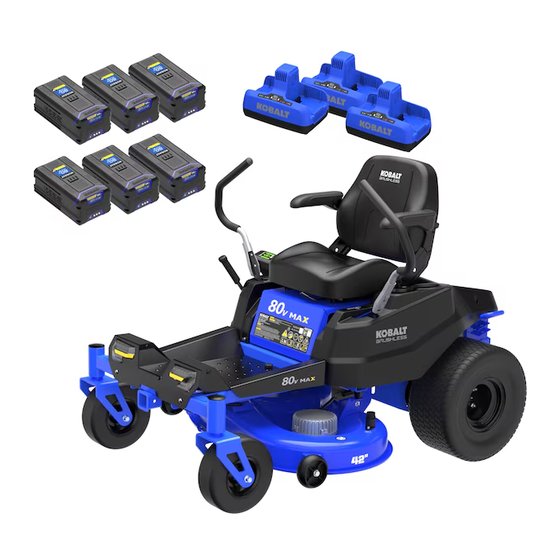
LAWN MOWER
ATTACH YOUR RECEIPT HERE
1
ITEM #5726741
MODEL #KZ 5680-06
ZERO TURN
Español p. 51
Advertisement
Chapters
Table of Contents

Related Manuals for Kobalt KZ 5680-06


Summary of Contents for Kobalt KZ 5680-06
- Page 1 ITEM #5726741 MODEL #KZ 5680-06 ZERO TURN LAWN MOWER KOBALT and logo design are trademarks or registered trademarks of LF, LLC. All rights Español p. 51 reserved. ATTACH YOUR RECEIPT HERE Serial Number Purchase Date Thank you for purchasing this KOBALT product.
-
Page 2: Table Of Contents
TABLE OF CONTENTS Product Specifications..........................Package Contents..........................Hardware Contents..........................Symbols..............................Safety Information..........................Preparation............................. Assembly Instructions..........................Operating Instructions..........................Care and Maintenance ......................... Transportation and Storage........................Troubleshooting............................. Warranty..............................Replacement Parts List......................... PRODUCT SPECIFICATIONS SPECIFICATIONS Cutting width 42 in Forward speed 4/6/8 mph Reverse speed 0-3 mph No-load speed... -
Page 3: Package Contents
PACKAGE CONTENTS... - Page 4 PACKAGE CONTENTS PART DESCRIPTION QUANTITY Steering control levers Seat USB charging port Cup holder Drive wheel Quick coulper Wash port Cutting deck Anti-scalp wheels Front wheels Headlights Height adjustment lever Seat adjustment lever Control panel Cutting blade Blade speed button Lamp switch Digital display screen Brightness adjustment button...
-
Page 5: Hardware Contents
HARDWARE CONTENTS (not to scale) Plain washer Hexagon Head Bolts, M10X25 Qty. 4 Qty. 7 Qty. 4 Starlock washer Disc Spring Customized bolt Qty. 2 Qty. 4 Qty. 2 Fixed seat Leaf spring lock nut Fixed seat Qty. 1 Qty. 2 Qty. - Page 6 HARDWARE CONTENTS (not to scale) Plain washers Qty. 4...
-
Page 7: Symbols
SYMBOLS SYMBOLS EXPLANATION Indicates a potential personal injury hazard. To reduce the risk of injury, user must read and understand operator’s manual before using this product. Always wear safety goggles or safety glasses with side shields and, as necessary, a full-face shield when operating this product. To reduce the risk of injury, keep hands and feet away from rotating parts. - Page 8 SYMBOLS Do not expose the product to rain or moist conditions. The following signal words and meanings are intended to explain the levels of risk associated with this product. SYMBOL SIGNAL MEANING Indicates an imminently hazardous situation, which, if not DANGER avoided, will result in death or serious injury.
-
Page 9: Safety Information
SAFETY INFORMATION GENERAL SAFETY WARNINGS WARNING Read all safety warnings, instructions, illustrations and specifications provided with this product. Failure to follow all instructions listed below may result in electric shock, fire and/or serious injury. Save all warnings and instructions for future reference. Work area safety •... - Page 10 Remove the key or disable the product when leaving the product unattended. The product is dangerous to untrained users. Battery tool use and care • Use only Kobalt 80-volt batteries (KB 280C-06, KB 2580C-06, KB 480C-06, KB 580C-06, KB 680C-06). • Use only Kobalt charger (KRC 0280-06, KRC 30-06, KDC 50-06).
- Page 11 SAFETY INFORMATION RIDE-ON MOWER SAFETY WARNINGS • Do not use the mower in bad weather conditions, especially when there is a risk of light- ning. This decreases the risk of being struck by lightning. • Thoroughly inspect the area for wildlife where the mower is to be used. Wildlife may be injured by the mower during operation.
- Page 12 SAFETY INFORMATION WARNING Use of this mower should be restricted to individuals who have read and understand and will follow the warnings and instructions that are printed in this manual and on the mower. WARNING • Carefully read all instructions on the mower and in the manual before attempting to assemble and operate the mower.
- Page 13 SAFETY INFORMATION • Never operate mower without a proper trail shield, discharge cover, switch control, or other safety device in place and in working order. Do not operate the mower with damaged safety devices; doing so can result in injury. •...
- Page 14 SAFETY INFORMATION • Use slow drive mode and drive carefully. • Avoid any sudden movement of the controls and use only slow, even acceleration. Towing • Tow only with a product that has a hitch designed for towing. Do not attach towed equipment except at the hitch point.
-
Page 15: Environmentally Safe Battery Disposal
• Slowly stand up from the seat. The cutting blades should stop. • If the cutting blades fail to stop when the operator is not in place, contact Kobalt after sales service immediately. ENVIRONMENTALLY SAFE BATTERY DISPOSAL The toxic and corrosive materials below are in the batteries used in this product: Lithium-ion, a toxic material. -
Page 16: Fcc 15 Compliance Statement
To ensure compliance, operations at closer than this distance is not recommended. FCC US AGENT / RESPONSIBLE PARTY: L.G. Sourcing, Inc. 1000 Lowe’s Blvd. Mooresville, NC 28117 USA 888-3KOBALT (888-356-2258) https://www.lowes.com/b/kobalt... -
Page 17: Preparation
SAFETY INFORMATION THE RECOMMENDED AMBIENT TEMPERATURE RANGE: ITEM TEMPERATURE Product storage 32°F (0°C) - 113°F (45°C) Product operation 32°F (0°C) - 113°F (45°C) Battery charging 39°F (4°C) - 104°F (40°C) Charger operation 39°F (4°C) - 104°F (40°C) Battery storage 32°F (0°C) - 113°F (45°C) Battery discharging 32°F (0°C) - 113°F (45°C) PREPARATION... -
Page 18: Assembly Instructions
ASSEMBLY INSTRUCTIONS 1. Installing the seat 1a. Lift the seat panel (a). 1b. Place the seat assembly over the seat panel and align holes. • Install the washers and nuts and tighten se- curely with a 10 mm socket and torque to 11-15 ft-lbs. - Page 19 ASSEMBLY INSTRUCTIONS 2. Installing the steering control levers The two levers control the mower’s speed, direc- tion, stopping, neutral lock, and parking brake. Levers are used to steer, accelerate, decelerate, stop, and change direction. Position 1 WARNING The left and right steering levers should be adjust- ed so that they align with each other when in the neutral position.
- Page 20 ASSEMBLY INSTRUCTIONS 3b. Align the holes in the mulch cover (c) and the holes in the mower housing. • Install and tighten all the bolts, fixed seat, washers, and nuts as shown. Note: The square mounting holes on the deck are intended for the bolts with square necks to insert through the bottom of the deck.
- Page 21 OPERATING INSTRUCTION 1. Adjusting the seat The position of the seat can be adjusted forwards or backwards to meet the comfort needs of the operator. Adjust the seat position to ensure you are able to make firm contact with the accelerator and brake pedal before operating the mower.
-
Page 22: Operating Instructions
OPERATING INSTRUCTIONS 3. Using the USB charging port The USB charging port (C) on the mower supplies 5 Volts DC with a maximum current of 2.1 amps for charging your cell phone, MP3 player, or other USB devices. Please refer to your device’s owner’s manual for its specific charging requirements. - Page 23 Refer to the Battery & Charger Manual for more information about how to use the battery charger. 6b. Connecting the batteries to the product WARNING Only use original Kobalt batteries with the product. • Make sure that the batteries are fully charged.
-
Page 24: Forward Travel
OPERATING INSTRUCTIONS 7. Steering The steering control levers control the direction of the mower as shown. Direction of arrows indicate FORWARD TRAVEL direction of mower movement. The left steering control lever controls the left rear drive wheel and the right steering control lever controls theright rear drive wheel. - Page 25 OPERATING INSTRUCTION 8b. Pull steering control levers inward to the NEU- TRAL position. 8c. Pull up the PTO switch to engage blades for mowing. Note: Engage blades only after steering control levers are moved into the NEUTRAL position. • NEVER engage blades when moving! Push steering control levers forward for forward motion and pull for reverse motion.
- Page 26 OPERATING INSTRUCTION R. Digital Display Screen: The digital display, located on the control panel, gives detailed information in the form of symbols, codes and numbers. Symbol Function User presence undetected. Battery level LED Lights The parking brake is engaged. Drive speed Blade speed Working time/ Error code Charging...
- Page 27 OPERATING INSTRUCTION 10. Stopping the product CAUTION Never make sudden stops or reverse direction, especially when maneuvering on a slope. The steering is designed for sensitive response. Rapid movement of the steering control levers in either direction could result in a reaction of the product that can cause serious injury. •...
-
Page 28: Care And Maintenance
Secure hair above shoulder level before starting work. Use of parts that are not authorized or approved by Kobalt may cause serious or fatal injury or property damage. 2. Clean the product •... - Page 29 CARE AND MAINTENANCE full charging cycle is not possible immediately after cutting, a 5-10 minute cycle will help maintain battery health. Fully re-charge the battery within 24 hours after use. To maintain proper calibration, run and charge the mower at least once a month. Complete a full charge every six months. •...
- Page 30 Drain oil from the oil drain outlet. Oil type SAE85W-140 Oil capacity 120-150 ml Contact your Kobalt after sales service to assist with the lubrication. Note: Replace the gearbox oil after the first 50 hours of operation, and subsequently, replace the oil every 200 hours.
- Page 31 CARE AND MAINTENANCE 9b. Remove the bolt, washer, blade (O), and blade insulator (d). Hardware Used Hexagon head bolt Plain washer 9c. Replace with the new blade. Install the blade nut, spacer, blade, and blade insulator in sequence. Ensure that the cutting edge of the blade is oriented toward the deck in the indicat- ed order.
- Page 32 CARE AND MAINTENANCE 10. Errors The CANBUS system will take action to protect the user and product when it detects an issue. When it acts to turn off the product or a component, it will indicate that an error has occurred, and that error will be shown on the digital display.
- Page 33 Controller overvoltage 1. Replace the battery pack with the same voltage platform; 2. Replace the controller and perform motor self-learn- ing again. TR12 Motor overtemperature 1. Check whether the tires are stuck; 2. The motor temperature is too high. Please wait for cooling before use and restart the power supply.
- Page 34 TR22 Electromagnetic valve error 1. Check whether the electromagnetic valve coil resis- tance is around 24Ω. If itis abnormal, the electromag- netic valve needs to be replaced; 2. Check whether there is a short circuit or open circuit in the wiring between the controller and the electromagnetic valve coil;...
- Page 35 TR32 Software authentication error 1. Restart the vehicle; 2. Replace the controller and perform motor self-learn- ing again. TR60 Controller undertemperature The temperature of the controller is too low. Please wait until the temperature rises to above -22.0°F and then restart the power supply. TR61 5V internal power supply failure 1.
- Page 36 Drive motor stalled 1. Check whether the tires are stuck; 2.Check the pin status of the encoder connector corresponding to the motor and whether the connector is connected properly; 3.Check whether the phase wire of the corresponding motor is damaged and whether the phase wire instal- lation is misaligned;...
- Page 37 TL15 Hardware Overcurrent 1. Check whether the phase wire of the corresponding motor is damaged and whether the mounting screws are tight; 2.Check the pin status of the encoder connector corresponding to the motor and whether the connector is connected properly; 3.
- Page 38 TL61 5V internal power supply failure 1. Check whether there is any short circuit abnormality in the 5V power supply; 2. Check whether the load is abnormal and whether there is a short circuit in the encoder or throttle circuit; 3.
- Page 39 Controller phase loss 1. Check whether the phase wire of the corresponding motor is damaged and whether the mounting screws are tight; 2. Replace the motor; 3. Replace the controller. MOSFET error 1. Check the status of the MOS tube of the controller; 2.
- Page 40 Blade motor stalled 1. Check whether the blade are stuck; 2.Check whether the phase wire of the corresponding motor is damaged and whether the phase wire instal- lation is misaligned; 3. Check parameter version; 4. Reset the PTO switch. Controller phase loss 1.
- Page 41 MR31 Blade switch verification error 1.Check the pin status of the PTO switch connector whether the connector is connected properly; 2. Check whether there is a short circuit or open circuit in the PTO switch wiring; 3. Check whether water has entered the PTO switch and whether the status of the switch changes nor- mally;...
- Page 42 PMU57 KSI Pre-MOS error 1. Restart the vehicle; 2. PMU hardware failure, please replace the PMU. PMU59 KSI MOS error 1. Restart the vehicle; 2. PMU hardware failure, please replace the PMU. PMU61 Battery pack 1 does not Replace the battery pack with the same voltage match platform.
-
Page 43: Transportation And Storage
For detailed information on shipping a battery, contact your authorized Kobalt after sales service. 3. Storing the product The following steps should be taken in order to prepare the product for storage. - Page 44 TRANSPORTATION AND STORAGE 4. Moving the mower manually • Disengage the blades and push the steering control levers outward to engage the parking brake. • Turn the start key to the OFF position. Remove the start key, and wait for all moving parts to stop before leaving the operating position.
- Page 45 TRANSPORTATION AND STORAGE 5a. Pull the two neutral bypass levers outwards and then downwards to unlock the wheels. 5b. Move the neutral bypass levers back into posi- tion to lock the wheels. WARNING Never drive mower with the neutral bypass lever working.
-
Page 46: Troubleshooting
Problem Possible Cause Corrective Action Product won’t move. There is no battery installed in Use only official Kobalt battery (or batteries). the battery compartment or the At least one is required for operation. battery is not an official Kobalt battery. - Page 47 Blade is bent. Replace the blade according to the manual and the height instructions. difference Uneven deck. Contact Kobalt after-sales service to level the is very large. deck. The actual mowing Deck mounting bolts are loose. Securely tighten deck mounting bolts. Note:...
- Page 48 12 hours nents. or blow dry before restarting. 3. Contact Kobalt after-sales service if the problem persists. The mower is Weeds and debris build up on Follow the instructions to clean the product blocked.
-
Page 49: Year Limited Warranty
This KOBALT zero-turn mower is warranted to the original purchaser from the original purchase date for five (5) years subject to the warranty coverage described herein. This KOBALT zero-turn mower is warranted for the original user to be free from defects in material and workmanship. -
Page 50: Replacement Parts List
REPLACEMENT PARTS LIST For replacement parts, call our customer service department at 888-356-2258, 8 a.m. - 8 p.m., EST, Monday - Sunday. You could also contact us at ascs@lowes.com. PART DESCRIPTION PART # Tire, Front Wheel, 11*4-6 R0205866-00 Rim, Front Wheel, 11*4-5 R0208535-00 Hexagon Head Bolts, M12*150 R0201465-00... - Page 51 ARTÍCULO #5726741 MODELO #KZ 5680-06 PODADORA DE GIRO CERO KOBALT y el diseño del logotipo son marcas comerciales o marcas registradas de LF, LLC. Todos los derechos reservados. ADJUNTE SU RECIBO AQUÍ Número de serie Fecha de compra Gracias por comprar este producto KOBALT.
-
Page 52: Especificaciones Del Producto
ÍNDICE Especificaciones del producto........................ Contenido del paquete........................... Aditamentos............................Símbolos..............................Información de seguridad........................Preparación............................Instrucciones de ensamblaje........................Instrucciones de funcionamiento......................Cuidado y mantenimiento........................Transporte y almacenaje........................Solución de problemas......................... Garantía..............................Lista de piezas de repuesto........................ESPECIFICACIONES DEL PRODUCTO ESPECIFICACIONES Ancho de corte 106.68 cm Velocidad de avance 6.43/9.65/12.87 km/h... -
Page 53: Contenido Del Paquete
CONTENIDO DEL PAQUETE... - Page 54 CONTENIDO DEL PAQUETE PIEZA DESCRIPCIÓN CANTIDAD Palancas de control de dirección Asiento Puerto de carga USB Portavasos Rueda motriz Acoplador rápido Puerto de lavado Plataforma de corte Ruedas protectoras Ruedas frontales Focos Palanca para ajuste de altura Palanca para ajuste del asiento Panel de control Cuchilla de corte Botón de velocidad de la cuchilla...
-
Page 55: Aditamentos
ADITAMENTOS (no se muestran a escala) Tuerca Arandela lisa Pernos de cabeza hexagonal, M10X25 Cant. 4 Cant. 7 Cant. 4 Arandela Starlock Resorte del disco Perno personalizado Cant. 2 Cant. 4 Cant. 2 Asiento fijo Contratuerca de ballesta Asiento fijo Cant. - Page 56 ADITAMENTOS (no se muestran a escala) Arandelas lisa Qty. 4...
-
Page 57: Símbolos
SÍMBOLOS SÍMBOLOS EXPLICACIÓN Indica que existe el riesgo de que se produzcan lesiones personales. Para reducir el riesgo de lesiones, el usuario debe leer y comprender el manual del usuario antes de utilizar este producto. Siempre use gafas o lentes de seguridad con protecciones laterales y, según sea necesario, un protector facial que cubra todo el rostro cuando opere este producto. - Page 58 SÍMBOLOS No exponga el producto a la lluvia o a condiciones de humedad. Se usan las siguientes indicaciones y sus significados para explicar los niveles de riesgo asociados a este producto. SÍMBOLO INDICACIÓN SIGNIFICADO Indica una situación de peligro inminente que, de no evitarse, PELIGRO ocasionará...
-
Page 59: Información De Seguridad
INFORMACIÓN DE SEGURIDAD ADVERTENCIAS GENERALES DE SEGURIDAD ADVERTENCIA Lea todas las advertencias de seguridad, instrucciones, imágenes y especificaciones que se incluyen con este producto. No seguir todas las instrucciones que se detallan a continuación podría provocar descargas eléctricas, incendios o lesiones graves. Guarde todas las advertencias e instrucciones para referencia futura. - Page 60 Uso y cuidado de herramientas con batería • Use solo baterías Kobalt de 80 voltios (KB 280C-06, KB 2580C-06, KB 480-06, KB 580C-06, KB 680C-06). • Use solo un cargador Kobalt (KRC 0280-06, KRC 30-06, KDC 50-06).
- Page 61 INFORMACIÓN DE SEGURIDAD • En condiciones de maltrato, es posible que salga líquido de la batería. Evite el contacto. Si entra en contacto con esa sustancia por accidente, enjuague la zona comprometida con agua. Si el líquido entra en contacto con los ojos, solicite atención médica. El líquido que sale de la batería puede provocar irritación o quemaduras.
-
Page 62: Lea Todas Las Instrucciones
INFORMACIÓN DE SEGURIDAD funcionamiento inesperado de la podadora puede provocar lesiones personales graves. El usuario y el técnico DEBEN revisar cuidadosamente TODOS los procedimientos, la • capacitación y las precauciones del manual de reparación que se relacionen con la seguridad del fabricante de equipos originales (OEM, por sus siglas en inglés) antes del uso, mantenimiento y servicio. - Page 63 INFORMACIÓN DE SEGURIDAD seguridad. • Nunca opere el producto mientras usa un teléfono móvil o cualquier otro dispositivo electrónico. Operar la unidad mientras está distraído puede aumentar el riesgo de lesiones personales graves al operador y a los transeúntes. • No opere el equipo con sandalias, tenis, calzado deportivo, pantalones cortos o cualquier tipo de ropa holgada.
- Page 64 INFORMACIÓN DE SEGURIDAD contacto con las cuchillas puede producir la amputación de manos y pies. • Si la máquina comienza a vibrar excesivamente, detenga el motor y busque la causa de inmediato. La vibración excesiva generalmente es una señal de que la podadora no está funcionando correctamente.
- Page 65 INFORMACIÓN DE SEGURIDAD podadora tipo tractor en un espacio interior seco y cerrado, fuera del alcance de los niños. • Apague y retire la llave de arranque antes de realizar tareas de mantenimiento, limpieza o extracción de material de la podadora tipo tractor. Funcionamiento en pendientes Las pendientes son un factor importante relacionado con los accidentes.
- Page 66 INFORMACIÓN DE SEGURIDAD una pendiente hacia agua, un muro de contención u otra bajada. Tenga especial cuidado al operar la podadora cerca de tales peligros. ADVERTENCIA Para reducir el riesgo de caer al agua, por escalones o por el borde de una bajada, siempre deje dos anchos de la podadora de espacio libre entre la podadora y el peligro.
- Page 67 INFORMACIÓN DE SEGURIDAD • NO las incinere. • NO las coloque donde puedan formar parte de ningún vertedero de desechos o flujo de desechos sólidos municipales. • Llévelas a un centro de reciclaje o eliminación certificado. ADVERTENCIA (PROPUESTA 65) Parte del polvo causado por el lijado eléctrico, el serruchado, la trituración, el taladrado y otras actividades de construcción contienen productos químicos que causan cáncer, defectos congénitos u otros daños en el aparato reproductivo.
-
Page 68: Preparación
INFORMACIÓN DE SEGURIDAD RANGO DE TEMPERATURA AMBIENTE RECOMENDADO: ARTÍCULO TEMPERATURA Almacenamiento del producto 0 °C a 45 °C (32 °F a 113 °F) Operación del producto 0 °C a 45 °C (32 °F a 113 °F) Carga de la batería 4 °C a 40 °C (39 °F a 104 °F) Operación del cargador 4 °C a 40 °C (39 °F a 104 °F) -
Page 69: Instrucciones De Ensamblaje
INSTRUCCIONES DE ENSAMBLAJE 1. Instalación del asiento 1a. Levante el panel del asiento (a). 1b. Coloque el ensamble del asiento sobre el panel del asiento y alinee los orificios. • Instale las arandelas y las tuercas, y apriételas firmemente con un dado de 10 mm y apriete de 1.52 kgf-m a 2.07 kgf-m (15 Nm a 20 Nm). - Page 70 INSTRUCCIONES DE ENSAMBLAJE 2. Instalación de las palancas de control de dirección Las dos palancas controlan la velocidad, la dirección, la detención, el bloqueo en punto muerto y el freno de mano de la podadora. Las palancas Position 1 se utilizan para conducir, acelerar, desacelerar, detener y cambiar de dirección.
- Page 71 INSTRUCCIONES DE ENSAMBLAJE 3b. Alinee los orificios de la cubierta de mantillo (c) y los orificios de la carcasa de la podadora. • Instale y apriete todos los pernos, el asiento fijo, las arandelas y las tuercas, como se muestra. Nota: los orificios de montaje cuadrados en la plataforma están destinados a que los pernos con cuello cuadrado se inserten a través de la parte...
-
Page 72: Instrucciones De Funcionamiento
INSTRUCCIONES DE FUNCIONAMIENTO 1. Ajuste del asiento La posición del asiento se puede ajustar hacia delante o hacia atrás para satisfacer las necesidades de comodidad del operador. Ajuste la posición del asiento para asegurarse de que pueda hacer un contacto firme con el pedal del acelerador y del freno antes de operar la podadora. - Page 73 INSTRUCCIONES DE FUNCIONAMIENTO 3. Uso del puerto de carga USB El puerto de carga USB (B) de la podadora suministra 5 voltios de CC con una corriente máxima de 2.1 amperios para cargar su teléfono celular, reproductor MP3 u otros dispositivos USB. Consulte el manual del propietario de su dispositivo para conocer sus requisitos de carga específicos.
- Page 74 INSTRUCCIONES DE FUNCIONAMIENTO 5. Remolque ADVERTENCIA Remolcar cargas puede ser riesgoso, especialmente en pendientes. • El peso total máximo (remolque y carga) no debe exceder los 136.07 kg (300 lb). • El peso máximo de remolque debe ser inferior a 20.41 kg (45 lb). •...
- Page 75 6b. Conexión de las baterías al producto ADVERTENCIA Utilice únicamente baterías Kobalt originales con el producto. • Asegúrese de que las baterías estén completa- mente cargadas.
- Page 76 INSTRUCCIONES DE FUNCIONAMIENTO 7. Dirección Las palancas de control de dirección controlan la dirección de la podadora, como se muestra. AVANCE La dirección de las flechas indica la dirección del movimiento de la podadora. La palanca de control de dirección izquierda controla la rueda motriz pos- terior izquierda y la palanca de control de dirección derecha controla la rueda motriz posterior derecha.
- Page 77 INSTRUCCIONES DE FUNCIONAMIENTO 8b. Jale de las palancas de control de dirección hacia adentro hasta la posición NEUTRAL. 8c. Abra el interruptor de PTO para enganchar las cuchillas para cortar el césped. Nota: enganche las cuchillas solo después de que las palancas de control de dirección se hayan movido a la posición NEUTRAL.
- Page 78 INSTRUCCIONES DE FUNCIONAMIENTO R. Pantalla digital: la pantalla digital, ubicada en el panel de control, brinda información detalla- da en forma de símbolos, códigos y números. Símbolo Función Presencia de usuario no detectada Nivel de la batería Luces LED El freno de mano está activado Velocidad de conducción Velocidad de la cuchilla Tiempo de trabajo/código de error...
- Page 79 INSTRUCCIONES DE FUNCIONAMIENTO 10. Detención del producto PRECAUCIÓN Nunca frene bruscamente ni invierta la dirección, especialmente al maniobrar en una pendiente. La dirección está diseñada para una respuesta sensible. El movimiento rápido de las palancas de control de dirección en cualquier dirección podría provocar una reacción del producto que puede provocar lesiones graves.
-
Page 80: Cuidado Y Mantenimiento
Asegure el cabello por encima del nivel de los hombros antes de comenzar a trabajar. El uso de piezas que no están autorizadas ni aprobadas por Kobalt puede provocar lesiones graves o mortales, o daños materiales. 2. Limpie el producto •... - Page 81 CUIDADO Y MANTENIMIENTO 4. Mantenimiento de la batería La podadora funciona con baterías de iones de litio que, si se mantienen adecuadamente, le proporcionarán años de vida útil. Para un cuidado adecuado, siga las siguientes instrucciones: • Cargue siempre la batería después de cada uso. Esto es especialmente crucial cuando las temperaturas caen por debajo de 0 °C (32 °F).
- Page 82 Capacidad de aceite 120 ml a 150 ml Póngase en contacto con el servicio postventa de Kobalt para recibir ayuda con la lubricación. Nota: reemplace el aceite de la caja de cambios después de las primeras 50 horas de operación y, posteriormente, reemplace el aceite cada 200 horas.
- Page 83 CUIDADO Y MANTENIMIENTO 9. Reemplazo de las cuchillas para podadora • Detenga el motor, retire la llave de arranque, ponga el freno de mano y retire las baterías del producto. • Eleve la altura de la plataforma de corte a su posición más alta para permitir el acceso a las cuchillas.
- Page 84 CUIDADO Y MANTENIMIENTO 9b. Retire el perno (LL), la arandela (MM), la cuchilla (O) y el aislante de la cuchilla (d). Aditamentos utilizados Pernos de cabeza hexagonal de 50.8 mm Arandelas lisa 9c. Remplace la cuchilla por una nueva. Instale la tuerca de la cuchilla, el espaciador, la cuchilla y el aislador de la cuchilla en secuencia.
- Page 85 CUIDADO Y MANTENIMIENTO 10. Errores El sistema CANBUS tomará medidas para proteger al usuario y al producto cuando detecte un problema. Cuando actúa para apagar el producto o un componente, indicará que se ha producido un error y ese error se mostrará en la pantalla digital. Todos los errores eléctricos tienen un código de letras seguido de un número.
- Page 86 Subvoltaje del controlador Reemplace el paquete de baterías completamente cargado; Sobrevoltaje del controlador 1. Reemplace el paquete de baterías con la misma plataforma de voltaje; 2. Reemplace el controlador y realice nuevamente el aprendizaje automático del motor. TR12 Exceso de temperatura del 1.
- Page 87 TR22 Error de válvula 1. Compruebe si la resistencia de la bobina de la electromagnética válvula electromagnética es de alrededor de 24 Ω. Si es anormal, es necesario reemplazar la válvula electromagnética; 2. Verifique si hay un cortocircuito o un circuito abierto en el cableado entre el controlador y la bobina de la válvula electromagnética;...
- Page 88 TR31 Error de verificación del 1. Verifique el estado del pasador del conector del interruptor del asiento interruptor del asiento y si el conector está conectado correctamente; 2. Verifique si hay un cortocircuito o un circuito abierto en el cableado del interruptor del asiento; 3.
- Page 89 TR70 Error de potenciómetro del 1. Verifique el estado del pasador del conector pedal del potenciómetro y si el conector está conectado correctamente; 2. Compruebe si el voltaje del acelerador está dentro del rango de 5 V ± 0.5; 3. Detecte el rango de cambio de voltaje del acelerador para ver si hay algún salto de voltaje anormal;...
- Page 90 Sobrevoltaje del controlador 1. Reemplace el paquete de baterías con la misma plataforma de voltaje; 2. Reemplace el controlador y realice nuevamente el aprendizaje automático del motor. TL12 Exceso de temperatura del 1. Compruebe si los neumáticos están atascados; motor 2.
- Page 91 TL23 Error de comunicación 1. Verifique el estado del pasador del conector de PMU del compartimiento de la CAN y si el conector está conectado correctamente; batería (PMU) 2. Compruebe si PMU CANL y CANH están en cortocircuito o en circuito abierto; 3.
- Page 92 TL69 La válvula electromagnética Habilite el dispositivo de bloqueo de la válvula izquierda se ha liberado electromagnética; TL70 Error de potenciómetro del 1. Verifique el estado del pasador del conector pedal del potenciómetro y si el conector está conectado correctamente; 2.
- Page 93 ML19 Error de secuencia 1. Compruebe si el interruptor del cortador está hacia operativa arriba; 2. Compruebe si el interruptor de recolección de césped está bien conectado. 3. Verifique si el estado del interruptor del asiento cambia normalmente. ML26 Error de tiempo de 1.
- Page 94 MR14 Sobrecorriente del software 1. Compruebe si las cuchillas están atascadas; 2. Verifique si el cable de fase del motor correspondiente está dañado y si los tornillos de montaje están apretados; 3. Restablezca el interruptor de PTO. MR15 Sobrecorriente del hardware 1. Verifique si el cable de fase del motor correspondiente está...
- Page 95 PMU37 Sobrevoltaje El voltaje es demasiado alto. Reinicie el suministro de electricidad. PMU38 Falla en la salida del 1. Reinicie el vehículo; suministro de electricidad 2. Reemplace el paquete de baterías y enciéndalo nuevamente. PMU41 No hay paquetes de 1. Reinicie el vehículo; baterías disponibles 2.
- Page 96 Se agotó el tiempo de 1. Verifique si los conectores de la pantalla y la PMU espera de CAN con PMU están conectados correctamente; 2. Reemplace la pantalla. 3. Reemplace la luz PMU. Se agotó el tiempo de 1. Verifique si los conectores de la pantalla y del espera de CAN con controlador de tracción izquierdo están conectados controlador de tracción...
-
Page 97: Transporte Y Almacenaje
Para obtener información detallada sobre el envío de una batería, comuníquese con el servicio posventa de Kobalt. 3. Almacenamiento del producto Debe seguir en orden los pasos a continuación antes de guardar el producto. - Page 98 TRANSPORTE Y ALMACENAJE • Ambiente de almacenamiento: guarde el producto en un área bien ventilada, limpia y seca. • Tenga en cuenta que el cargador de la batería no se puede utilizar en un ambiente húmedo. • Procedimiento de carga: consulte la sección Carga y también el Manual del cargador de la batería para obtener instrucciones completas sobre cómo usar el cargador y cargar la batería de manera eficaz.
- Page 99 TRANSPORTE Y ALMACENAJE 5. Palanca de derivación de neutral Las palancas de derivación de neutral controlan dos ruedas motrices. La palanca cerca del deflec- tor posterior controla la rueda motriz derecha y la palanca cerca de la plataforma controla la rueda motriz izquierda.
- Page 100 TRANSPORTE Y ALMACENAJE 5b. Mueva las palancas de derivación de neutral a su posición para bloquear las ruedas. ADVERTENCIA Nunca conduzca la podadora con la palanca de derivación de neutral funcionando. ¡Instale siempre la palanca de derivación de neu- tral en la posición original antes de conducir! ¡No volver a instalar la palanca podría causar daños graves a la podadora y anular su garantía! ADVERTENCIA...
-
Page 101: Solución De Problemas
No hay ninguna batería instalada Utilice únicamente baterías oficiales de mueve. en el compartimiento de las Kobalt. Se requiere al menos una para su baterías o la batería no es una funcionamiento. batería oficial de Kobalt. La batería no está cargada. - Page 102 Plataforma dispareja. Póngase en contacto con el centro de es muy grande. servicio posventa de Kobalt para nivelar la plataforma. La altura de corte Los pernos de montaje de la Apriete firmemente los pernos de montaje de real no coincide con plataforma están sueltos.
- Page 103 Plataforma dispareja. Póngase en contacto con el centro de servicio posventa de Kobalt para nivelar la plataforma. Los pernos de montaje de la Apriete firmemente los pernos de montaje de plataforma están sueltos.
-
Page 104: Garantía Limitada De 5 Años
(5) años y está sujeta a la cobertura de garantía que se describe en el presente. Esta podadora de giro cero KOBALT tiene una garantía para el usuario original contra defectos en los materiales y la mano de obra. -
Page 105: Lista De Piezas De Repuesto
LISTA DE PIEZAS DE REPUESTO Para obtener piezas de repuesto, llame a nuestro Departamento de Servicio al Cliente al 888-356-2258, de lunes a domingo de 8 a.m. a 8 p.m., hora estándar del Este. También puede ponerse en contacto con nosotros a través de ascs@lowes.com. PIEZA DESCRIPCIÓN PIEZA #...
Need help?
Do you have a question about the KZ 5680-06 and is the answer not in the manual?
Questions and answers