
Related Manuals for Terex Genie GTH-3007 AU.3


Summary of Contents for Terex Genie GTH-3007 AU.3
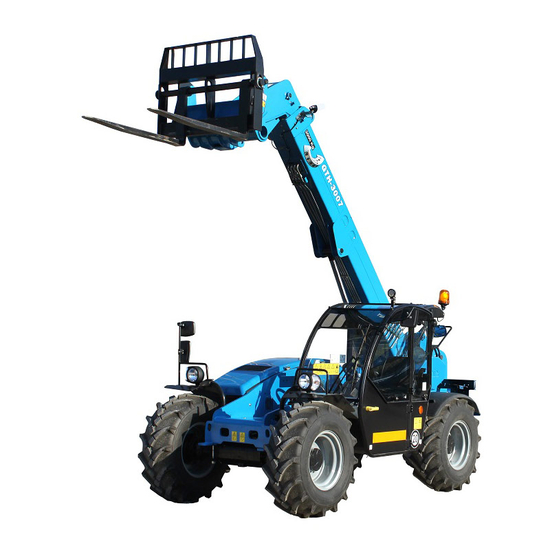
- Page 1 Operator’s Manual Serial number range GTH-3007 AU.3 From serial n.: GTH300716M-101 Original Instructions First Edition First Printing Part No. 57.0009.0739...
-
Page 2: Table Of Contents
33 Kimberley St First Edition: First Printing, November 2018 Darra, QLD 4076 Australia Genie is a registered trademark of Terex South Dakota, Inc. in the U.S.A. and many other Parts and Service Support countries. “GTH” is a trademark of Terex South 1800 788 633 Dakota, Inc. -
Page 3: About This Manual
First Edition - First Printing November 2018 Introduction About This Manual Product Identification Genie appreciates your choice of our machine for The machine serial number is located on the serial your application. Our number one priority is user label. safety, which is best achieved by our joint efforts. This book is an operation and daily maintenance Serial number Serial number... -
Page 4: Bulletin Distribution And Compliance
November 2018 First Edition - First Printing Introduction Bulletin Distribution and Contacting the Manufacturer Compliance At times it may be necessary to contact Genie. When you do, be ready to supply the model number Safety of product users is of paramount importance and serial number of your machine, along with your to Genie. - Page 5 First Edition - First Printing November 2018 Introduction Danger Failure to obey the instructions and safety rules in this manual will result in death or serious injury. Do Not Operate Unless: You learn and practice the principles of safe machine operation contained in this operator’s manual.
-
Page 6: Hazard Classification
November 2018 First Edition - First Printing Introduction Hazard Classification Standards Safety alert symbol - used to The following standards and/or regulations apply to alert you to potential personal this machine: injury hazards. Obey all safety messages that follow this Directive symbol to avoid possible injury AS 1418.19-2007 Cranes, hoists and winches. -
Page 7: Symbol And Hazard Pictorials Definitions
First Edition - First Printing November 2018 Symbol and Hazard Pictorials Definitions Maintain required Electrocution Crush hazard. No people under Read the Tip-over hazard clearance. hazard load operator's manual . Explosion hazard Do not use. Apply maintenance Always wear seat Crush hazard. -
Page 8: General Safety
November 2018 First Edition - First Printing General Safety GTH-3007 AU.3 Part No. 57.0009.0739... - Page 9 First Edition - First Printing November 2018 General Safety Part No. 57.0009.0739 GTH-3007 AU.3...
-
Page 10: Work Area Safety
November 2018 First Edition - First Printing Work Area Safety Overturning Hazards Using the load chart, confirm that When driving, keep the boom at the load is within the rated capacity or below horizontal and keep the of the machine. Do not exceed the load close to the ground. - Page 11 First Edition - First Printing November 2018 Work Area Safety Traveling on Slopes Hazards Fall Hazards When driving, keep the boom at Always wear a seat belt when or below horizontal and keep the operating the machine. load close to the ground. When the machine is unloaded, travel with the forks Always remain completely inside the cab when or attachment downhill.
- Page 12 November 2018 First Edition - First Printing Work Area Safety Collision Hazards Falling Object Hazards Operate the machine at speeds that will keep the Do not put the transmission into gear unless the load under control. Start and stop movements parking brake is set.
-
Page 13: Damaged Machine Hazards
First Edition - First Printing November 2018 Work Area Safety Bodily Injury Hazards Damaged Machine Hazards Always adjust the seat and fasten Do not use a damaged or malfunctioning machine. the seat belt before starting the engine. Conduct a thorough pre-operation inspection of the machine and test all functions before each work shift. -
Page 14: Component Damage Hazards
November 2018 First Edition - First Printing Work Area Safety Component Damage Hazards Explosion and Fire Hazards Do not use any battery or charger greater than 12V Do not start the engine if you smell or detect liquid to jump-start the engine. petroleum gas (LPG), gasoline, diesel fuel or other explosive substances. -
Page 15: Electrocution Hazards
First Edition - First Printing November 2018 Work Area Safety Electrocution Hazards Do not use the machine as a ground for welding. This machine is not electrically insulated and will not provide protection from contact with or proximity to Always contact the electrical power line owner. The electrical current. -
Page 16: Employer's Responsibilities
November 2018 First Edition - First Printing Work Area Safety Battery Safety Burn Hazards Electrocution Hazard Batteries contain acid. Avoid contact with electrical terminal. Always wear protective clothing and eye wear when Using the Charger (if equipped), be sure the device working with batteries. -
Page 17: Safety Precautions
First Edition - First Printing November 2018 Safety Precautions Requirements for service Requirements for Machine personnel Operators Personnel in charge of machine maintenance The operators who use the machine regularly or shall be qualified, specialised in the maintenance occasionally (i.e. for transport reasons) shall have of telehandlers, and shall have the following the following prerequisites: prerequisites:... -
Page 18: Working Clothes
November 2018 First Edition - First Printing Safety Precautions Working clothes Personal protective equipment During work, but especially when maintaining or Under special working conditions, the following repairing the machine, operators must wear suitable personal protective equipment should be used: protective clothing: •... - Page 19 First Edition - First Printing November 2018 Safety Precautions Control Indicators and Interlocks Seat Interlock Several control indicators and interlocks have been This micro switch is located inside the seat cushion, fitted to the machine. They must never be tampered and it prevents any machine transmission movements with or removed.
-
Page 20: Legend
November 2018 First Edition - First Printing Legend 1. Left/right level indicator 7. Fuel filler 2. Operator’s manual storage 8. Hydraulic oil level gauge (door internal side) 9. Engine (on opposite side of 3. Left rear view mirror machine) 4. Right rear view mirrors 10. -
Page 21: Controls
First Edition - First Printing November 2018 Controls Part No. 57.0009.0739 GTH-3007 AU.3... - Page 22 November 2018 First Edition - First Printing Controls Control Panel 16. Work lights switch (if equipped) 1. Steering wheel 17. Steering column tilt adjustment lock 2. Emergency stop push-button 18. A/C switch (if equipped) 3. Seat controls 19. Cab heater fan switch 4.
- Page 23 First Edition - First Printing November 2018 Controls Steering wheel Parking brake switch Turn the steering wheel to the right to turn the Push the bottom of the rocker switch to turn the front wheels to the right. Turn the steering wheel parking brake on.
- Page 24 November 2018 First Edition - First Printing Controls 19 Cab heater fan switch 26 Road/Job-site switch Push the bottom of the switch to turn the cab Push the bottom of the rocker switch to select heater fan on: first position for low speed and job-site mode.
- Page 25 First Edition - First Printing November 2018 Controls °c 1230 engine rpm 000000.0 Instrument Panel 14. Not active 1. Low engine oil pressure indicator light 15. Engine coolant temperature gauge with high 2. Parking brake engaged indicator light coolant temperature indicator light 3.
- Page 26 November 2018 First Edition - First Printing Controls 1 Low engine oil pressure indicator light 12 Engine Critical Fault indicator light When illuminated this light indicates that the engine oil This light comes on to warn of a problem with the pressure is too low which can lead to engine damage.
-
Page 27: Inspections
First Edition - First Printing November 2018 Inspections Pre-operation Inspection Fundamentals It is the responsibility of the operator to perform a pre-operation inspection. The pre-operation inspection is a visual inspection Do Not Operate Unless: performed by the operator prior to each work shift. The inspection is designed to discover if anything is apparently wrong with a machine before the operator ... -
Page 28: Pre-Operation Inspection
November 2018 First Edition - First Printing Inspections Pre-operation Inspection Be sure that the operator’s and safety manuals Limit switches are complete, legible and in the storage container Lights, alarms and beacons located in the cab. Pins, nuts, bolts and other fasteners ... -
Page 29: Function Test Fundamentals
First Edition - First Printing November 2018 Inspections Function Test Fundamentals The function tests are designed to discover any malfunctions before the machine is put into service. The operator must follow the step-by-step instructions to test all machine functions. A malfunctioning machine must never be used. If Do Not Operate Unless: malfunctions are discovered, the machine must be tagged and removed from service. -
Page 30: Function Tests
November 2018 First Edition - First Printing Inspections Function Tests Test the Boom Functions Joystick Using the control handle, momentarily raise the Select a test area that is firm, level and free of boom and extend the boom, tilt the forks up obstruction. -
Page 31: Test The Transmission And Brakes
First Edition - First Printing November 2018 Inspections 13 Straighten the wheels. 22 Move the transmission control lever to the reverse direction. Push down lightly on the accelerator 14 Rotate the steer selector to the middle position pedal to increase the RPM’s and slowly let up on to select two-wheel steer. - Page 32 November 2018 First Edition - First Printing Inspections Test the Road Transfer Mode Test the Emergency Stop Push button 35 Press the Emergency Stop Push button down 28 Set the steer select switch to road transfer mode. during a movement. 29 Attempt to: operate the boom ...
-
Page 33: Workplace Inspection Checklist
First Edition - First Printing November 2018 Inspections Workplace Inspection Checklist Be aware of and avoid the following hazardous situations: drop-offs or holes bumps, floor obstructions or debris Do Not Operate Unless: sloped surfaces You learn and practice the principles of safe ... - Page 34 November 2018 First Edition - First Printing Inspections Inspection for Decals Use the pictures on the next page to verify that all decals are legible and in place. Below is a numerical list with quantities and descriptions. Part No. Decal Description Part No.
- Page 35 First Edition - First Printing November 2018 Inspections AUS4530 82560 09.4618.1670 09.4618.1419 09.4618.1993 09.4616.0002 237720 AUS4530 09.4618.1025 09.4618.0776 09.4618.1818 215646 09.4618.1375 09.4618.1682 52475 09.4618.1645 09.4618.1995 09.4618.1999 09.4618.0916 237721 09.4618.1781 09.4618.1682 09.4618.1782 09.4618.1423 09.4618.1398 09.4618.1691 09.4618.0922 09.4618.1458 09.4618.0916 52475 09.4618.1992 09.4618.1687 09.4618.1713 09.4618.1689 1272242...
-
Page 36: Operating Instructions
November 2018 First Edition - First Printing Operating Instructions Fundamentals The Operating Instructions section provides instructions for each aspect of machine operation. It is the operator’s responsibility to follow all the safety rules and instructions in the operator’s, safety and responsibilities manuals. Do Not Operate Unless: A variable reach rough terrain forklift truck is defined as a wheeled type truck designated... -
Page 37: Adjusting The Seat
First Edition - First Printing November 2018 Operating Instructions Adjusting the Seat Fastening the Seat Belts Sit correctly in the driving seat; then: • The seat belt is equipped with a reel retractor. • To fasten the belt, pull tab 1 and push it into To adjust the seat position, move lever A and slide buckle 2. -
Page 38: Adjusting The Mirrors
November 2018 First Edition - First Printing Operating Instructions Adjusting the mirrors The machine is fitted with four rear view mirrors. To adjust their positions, manually rotate them to the position(s) which provides optimal visibility. 1. Allows checking the area behind the machine, on the right-hand side. -
Page 39: Parking Brake
First Edition - First Printing November 2018 Operating Instructions Parking Brake Starting in Cold Condition Use the parking brake switch to apply the parking In cold conditions, 20°F / -6°C and below, warm brake before raising the boom or leaving the the engine for 5 minutes before operating to machine. -
Page 40: Emergency Exit
November 2018 First Edition - First Printing Operating Instructions Emergency Exit Transmission Control The rear window of the cabin can be used as an Use the transmission control lever to control the escape route in case of emergency. direction of machine travel. In an emergency, break the rear window glass To drive forward, move the transmission control using the "Emergency break glass hammer"... -
Page 41: Transporting A Load
First Edition - First Printing November 2018 Operating Instructions Transporting a Load Raising and Placing a Load Center the load on the forks. Position the load so The load chart in the cab shows the operating that it is completely against the back of the fork limits of a properly maintained and operated frame. - Page 42 November 2018 First Edition - First Printing Operating Instructions Placing the load Travel to the desired work site and carefully stop the machine. Put the transmission in neutral. Apply the parking brake. Gradually move the controller to raise and extend the boom to the required height. Gradually move the controller to raise and retract the boom.
- Page 43 First Edition - First Printing November 2018 Operating Instructions Controller movements - Single Joystick Joystick with function Joystick with function enable switch (B) and enable switch (B) yellow roller switch (C) Hydraulic quick coupling (if equipped) Lock or unlock hydraulic quick coupling by simultaneously pressing hydraulic quick coupling lock/unlock switch, function enable button (B) and button (A).
-
Page 44: Load Management System
November 2018 First Edition - First Printing Operating Instructions Load Management System The risks associated with the following hazards The Load Management System (LMS) is a safety are not controlled by the LMS: system designed to monitor the telehandlers stability condition during the loading/unloading •... -
Page 45: Display Unit
First Edition - First Printing November 2018 Operating Instructions Although the LMS warns the operator when There are two main screens used to display they are reaching the rated capacity, it does information about the condition of the machine not replace the operator's experience in the during normal operation. -
Page 46: Access Methods
November 2018 First Edition - First Printing Operating Instructions USB port (7) (if equipped with enhanced display). Used to load LMS software, machine configuration, load tables and operator access data ( not avaible with standard display). For machines fitted with standard display, a USB port is located under the dashboard, next to the brake fluid reservoir. -
Page 47: Changing Attachments
First Edition - First Printing November 2018 Operating Instructions Changing Attachments Procedure: Start the engine; Follow appropriate instructions from within the If login is required, use encoder wheel button manual to fit desired attachment. to select user name and enter 4-digit code. Ensure the attachment is lowered to the ... -
Page 48: Primary Home Screen
November 2018 First Edition - First Printing Operating Instructions Operating Instructions Overriding the LMS Overriding the LMS may result in the machine overturning and cause death or serious injury to the operator and/or by-stander. The LMS should only be overridden when a motion inhibited by the alarm condition is necessary to recover the machine from a Figure 8 Override key switch A... -
Page 49: Secondary Home Screen
First Edition - First Printing November 2018 Operating Instructions Time/date (18). Current time/date. This value depending on outrigger position. The chart's load toggles between time and date every 10 seconds. zones change colour from green to orange or red when the actual load reaches 90% and 100% of Machine status (19). -
Page 50: Alarms And Warnings
November 2018 First Edition - First Printing Operating Instructions Primary home screen (28). Press button next to The LMS override key should be kept by the icon to return to the primary home screen. site manager or the person responsible for jobsite safety. - Page 51 First Edition - First Printing November 2018 Operating Instructions Part No. 57.0009.0739 GTH-3007 AU.3...
-
Page 52: Using The Load Charts
November 2018 First Edition - First Printing Operating Instructions Load Management System Using The Load Charts Override Key Switch The load chart provided in the cabin (see section This switch allows the override of the LMS in order "load charts") specify operating limits for stationary to recover the machine: and "pick and carry"... - Page 53 First Edition - First Printing November 2018 Operating Instructions Quick Attach Instructions 1. Drive to the place where you will release the 10. Retract and raise the attachment a small distance. mounted attachment (when possible, a solid It will center automatically on the quick coupling and sheltered site).
-
Page 54: Jump Starting The Machine
November 2018 First Edition - First Printing Operating Instructions Jump Starting the Machine Driving on a slope Jump starting at the battery or battery replacement When the machine is loaded, always travel with is required when the battery is discharged to the the load uphill. -
Page 55: Road Or Site Transfer
First Edition - First Printing November 2018 Operating Instructions Engine Condition Indicator Road or site transfer If the Alert indicator light and/or the Engine Critical When travelling on public roads, strictly obey the Fault indicator light switches on, contact service local or national road traffic regulations. -
Page 56: Moving A Disabled Machine
November 2018 First Edition - First Printing Operating Instructions Moving a disabled machine 5. Screw in the brake release screws (A), 1/4 turn Tow the machine only when no alternative is possible, at a time, in sequence, until the torque drops off since this operation may result in serious damage to sharply (the wheels are free). -
Page 57: Short Inactivity
First Edition - First Printing November 2018 Parking and Storage Short inactivity Machine storage Always park the machine in a safe way after a working In case of extended inactivity of the machine, follow day, a shift and at night. the above precautions. -
Page 58: Cleaning And Washing The Machine
November 2018 First Edition - First Printing Parking and Storage Machine disposal Cleaning and washing the machine At the end of the machine life, call in a specialized firm to dispose of it in compliance with the local or Clean the machine in accordance with the following national regulations. -
Page 59: Observe And Obey
First Edition - First Printing November 2018 Transport and Lifting Instructions Observe and Obey: Be sure the vehicle capacity, loading surfaces Genie customers needing to containerize any and chains or straps are sufficient to withstand lift or Genie product should source a qualified the machine weight. - Page 60 November 2018 First Edition - First Printing Transport and Lifting Instructions Securing to Truck or Trailer for Transit Securing the Chassis Turn the key switch to the off position and remove Use chains of ample load capacity. the key before transporting. Use a minimum of 4 chains.
- Page 61 First Edition - First Printing November 2018 Transport and Lifting Instructions Lifting Instructions Fully lower and retract the boom. Determine the center of gravity of your machine using the picture on this page. Remove all loose items on the machine. Observe and Obey: Attach the rigging only to the designated lifting points on the machine.
-
Page 62: Maintenance
November 2018 First Edition - First Printing Maintenance Check the Tire Pressure Tip-over hazard. An over-inflated tire can explode which may compromise machine Observe and Obey: stability and cause the machine to tip over. Tip-over hazard. The use of temporary flat tire ... -
Page 63: Check The Engine Oil Level
First Edition - First Printing November 2018 Maintenance Check the Engine Oil Level Check the Hydraulic Oil Level Maintaining the proper engine oil level is essential Maintaining the hydraulic oil at the proper level is to good engine performance and service life. essential to machine operation. -
Page 64: Check The Engine Coolant Level
November 2018 First Edition - First Printing Maintenance Check the Engine Coolant Level Check the Battery Proper battery condition is essential to good Maintaining the engine coolant at the proper level machine performance and operational safety. is essential to engine service life. Improper coolant Improper fluid levels or damaged cables and level will affect the engine’s cooling capability and connections can result in component damage and... -
Page 65: Scheduled Maintenance
First Edition - First Printing November 2018 Maintenance Scheduled Maintenance Machines that have been out of service for more than three months must receive the quarterly Checklist A inspection before they are put back into service. Manuals and decals Pre-operation inspect Model Function tests Serial number... -
Page 66: Inspect The Manuals And Decals
November 2018 First Edition - First Printing Maintenance Inspect the Manuals and Decals 3 Open the operator's manual to the decals Genie specifications require that this procedure be inspection section. Carefully and thoroughly performed every 8 hours or daily, whichever comes inspect all decals on the machine for legibility first. -
Page 67: Perform Pre-Operation Inspection
First Edition - First Printing November 2018 Maintenance Perform Pre-operation Inspection Perform Function Tests Genie specifications require that this procedure be Genie specifications require that this procedure be performed every 8 hours or daily, whichever comes performed every 8 hours or daily, whichever comes first. -
Page 68: Lubricate The Boom
November 2018 First Edition - First Printing Maintenance Lubricate the Boom Perform Engine Maintenance - Perkins Models Genie specifications require that this procedure be performed every 8 hours or daily, whichever comes first. Engine specifications require that this procedure be performed every 8 hours or daily, whichever comes Greasing the specified locations is essential for good first. -
Page 69: Perform Axle Maintenance
First Edition - First Printing November 2018 Maintenance Perform Axle Maintenance Perform Axle Maintenance Axle specifications require that this procedure be Axle specifications require that this one-time performed after the first 10 hours. procedure be performed after the first 100/250 hours. Differential lubricating oil - check/add Differential lubricating oil - change Planetary reduction lubricating oil - check/add... -
Page 70: Attachments
November 2018 First Edition - First Printing Attachments Genie Approved Attachments List: This machine can be equipped with several attachments. • Floating Fork Use only Genie approved attachments specified in (part number AUS10104) this section. • Fixed Hook Information about how to fit and replace attachments (part number AUS10011) on the machine can be found in section “Quick Attach •... - Page 71 First Edition - First Printing November 2018 Attachments Fixed Hook Application Quick-coupling fitted attachment for lifting loads by (part number AUS10011) means of special slings. Safety Strictly obey the general safety precautions given in section “Safety”. Do not oscillate the load. Do not drag hooked loads.
-
Page 72: Extension Jib
November 2018 First Edition - First Printing Attachments 2 m Extension Jib Application Quick-coupling fitted attachment for lifting loads (part number AUS100020) by means of slings. Safety Strictly obey the general safety precaution given in “Safety” chapter. Never lift incorrectly slung loads. Avoid abrupt acceleration or deceleration. -
Page 73: Operation
First Edition - First Printing November 2018 Attachments Forks with Hydraulic Side-Shift Application (part number AUS10025) Quick-coupling fitted attachment for handling palletised loads with possibility of shifting the load to the side by ± 100mm. Safety Strictly obey the general safety precaution given in section “Safety”. - Page 74 November 2018 First Edition - First Printing Attachments 700 Litre Bucket Attachment suitable for moving loose material. (part number AUS10004) Do not use for digging operations. Application Quick coupling attachment for moving soil, sand, debris, grains, etc. Safety Strictly obey the general safety precautions given in section “Safety”.
- Page 75 First Edition - First Printing November 2018 Attachments 1050 Litre Bucket Attachment suitable for moving loose material. (part number AUS10005) Do not use for digging operations. Application Quick coupling attachment for moving soil, sand, debris, grains, etc. Safety Strictly obey the general safety precautions given in section “Safety”.
- Page 76 November 2018 First Edition - First Printing Attachments Suspended Load Hazards Work Area Safety Overturning Hazards General Safety Do not lift a suspended load without the proper and legible load capacity chart for the attachment/ Do not lift a suspended load without first telehandler combination you are using.
-
Page 77: Fall Hazards
First Edition - First Printing November 2018 Attachments Identify the proper lifting points of the load, taking lowest possible position. into consideration the center of gravity and load When sloping downward with loaded material, stability. proceed into reverse Do not attempt to use the telehandler frame- When driving on a rise with empty shovel, proceed levelling to compensate for a swinging load or to into reverse. -
Page 78: Collision Hazards
November 2018 First Edition - First Printing Attachments Collision Hazards Falling Object Hazards Be sure that the load is clear of any adjacent Do not raise the load into the obstacles before lifting. fall zone shown. When visibility is or could be obstructed, near or at the load placement, the operator shall use alternative or additional means to safely lift the load, such as a qualified signal person/dogger. - Page 79 First Edition - First Printing November 2018 Attachments Lifting a Suspended Load Travelling Verify that landing point is level and can safely Be sure that the path of travel is level and capable support the load. of supporting the telehandler with its load. Ground side slope must not exceed the values listed on Properly secure the attachment to the telehandler the load chart.
-
Page 80: Placing The Load
November 2018 First Edition - First Printing Attachments Placing the Load Signal Person Ask a signal person/dogger to assist with placing A signal person is recommended when: the load if visibility will be obstructed at the point of The point of operation, meaning the load travel or operation. - Page 81 First Edition - First Printing November 2018 Attachments WHISTLE, WHISTLE, BELL OR BELL OR MOTION HAND SIGNAL MOTION HAND SIGNAL BUZZER BUZZER SIGNAL SIGNAL 1 long Hoisting 2 short Hoisting ——— raise • • lower Luffing 3 short Luffing 4 short boom up •...
-
Page 82: Specifications
November 2018 First Edition - First Printing Specifications GTH-3007 Height, stowed 2.3 m Length, stowed, to attachment frame 4.66 m Width, standard tires 1.99 m Wheelbase 2.66 m Ground clearance, center 0.43 m Weight 6,060 kg Working fork height, 6.89 m maximum Horizontal reach maximum 3.86 m... -
Page 83: Load Charts
First Edition - First Printing November 2018 Load Charts Refer to load charts provided in cabin for comprehensive operating restrictions, e.g. pick and carry con- figuration, allowable slope for various operating modes and in-service wind speed rating. GTH-3007 AU.3, Standard Forks Part No. - Page 84 November 2018 First Edition - First Printing Load Charts GTH-3007 AU.3, Fixed Hook GTH-3007 AU.3 Part No. 57.0009.0739...
- Page 85 First Edition - First Printing November 2018 Load Charts GTH-3007 AU.3, 2 m JIB Part No. 57.0009.0739 GTH-3007 AU.3...
- Page 86 November 2018 First Edition - First Printing Load Charts GTH-3007 AU.3, Side Shift Forks GTH-3007 AU.3 Part No. 57.0009.0739...
- Page 87 First Edition - First Printing November 2018 Load Charts GTH-3007 AU.3, Extended Forks Part No. 57.0009.0739 GTH-3007 AU.3...
- Page 88 November 2018 First Edition - First Printing Load Charts GTH-3007 AU.3, Fork Rotator GTH-3007 AU.3 Part No. 57.0009.0739...
- Page 89 First Edition - First Printing November 2018 Load Charts GTH-3007 AU.3, 700L GP Bucket Part No. 57.0009.0739 GTH-3007 AU.3...
- Page 90 November 2018 First Edition - First Printing Load Charts GTH-3007 AU.3, 1050L GP Bucket GTH-3007 AU.3 Part No. 57.0009.0739...
- Page 91 First Edition - First Printing November 2018 Load Charts GTH-3007 AU.3, 4-in-1 Bucket 500L Part No. 57.0009.0739 GTH-3007 AU.3...
- Page 92 www.genielift.com...
Need help?
Do you have a question about the Genie GTH-3007 AU.3 and is the answer not in the manual?
Questions and answers