Table of Contents
Advertisement
Quick Links
53000 BTU/H 15.5KW
SKU: 75210
INSTALLATION AND USER'S GUIDE
DANGER
Read all safety warnings and instructions. Failure to follow the warnings
and instructions may result in electric shock, fire and/or serious injury.
Save all warnings and instructions for future reference.
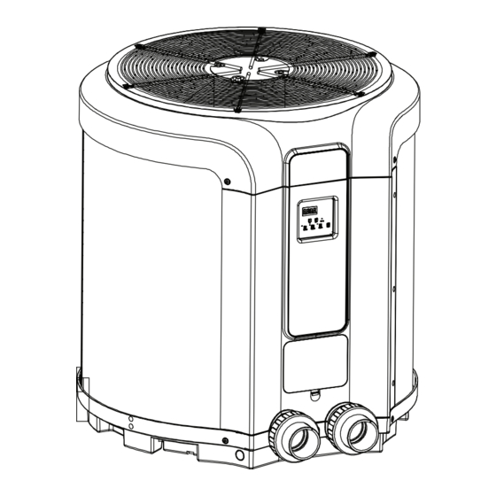
POOL HEAT PUMP
POOL HEAT PUMP
65000 BTU/H 19KW
SKU: 75211
137000 BTU/H 40.1KW
SKU: 75212
75210
75211
75212
Advertisement
Table of Contents

Related Manuals for XtremepowerUS 75210


Summary of Contents for XtremepowerUS 75210
- Page 1 POOL HEAT PUMP POOL HEAT PUMP 53000 BTU/H 15.5KW 65000 BTU/H 19KW 137000 BTU/H 40.1KW SKU: 75210 SKU: 75211 SKU: 75212 INSTALLATION AND USER’S GUIDE 75210 75211 75212 DANGER Read all safety warnings and instructions. Failure to follow the warnings and instructions may result in electric shock, fire and/or serious injury.
-
Page 3: Table Of Contents
TABLE OF CONTENTS TABLE OF CONTENTS IMPORTANT SAFETY INSTRUCTIONS Legends and Symbols GENERAL SAFETY INITIAL STARTUP PRODUCT INFORMATION INTRODUCTION SPECIFICATION INSTALLATION INSTALLATION INSTRUCTIONS PLUMBING ELECTRICAL CONNECTIONS OPERATION CONTROL PANEL OVERVIEW PERAMETER DISPLAY READINGS CONTROL PANEL OPERATION ERROR CODES TROUBLESHOOTING MAINTENANCE REPLACEMENT PARTS Parts Diagram DISCLAIMER... -
Page 4: Important Safety Instructions
IMPORTANT SAFETY INSTRUCTIONS This guide provides instructions for installing and using the POOL HEAT PUMP. If you have any questions about the equipment, please contact XtremepowerUS. This guide contains important information about safely installing and operating this product. After installation, make sure to share this information with the owner/operator or leave it with them for their reference. -
Page 5: General Safety
IMPORTANT SAFETY INSTRUCTIONS WARNING GENERAL SAFETY Please carefully read and retain all safety warnings and instructions. Non-compliance with these guidelines could lead to electric shock, fire, and/or grave injury. Not every potential scenario can be anticipated and detailed in this manual. Operators are expected to exercise common sense and caution, which are indispensable and beyond the scope of this product's design. -
Page 6: Product Information
PRODUCT INFORMATION PRODUCT INFORMATION INTRODUCTION The pool heat pump, a self-contained unit, is engineered specifically for heating pools. Crafted with attention to detail, it aims to surpass industry standards with its high-quality components. This includes an electronic board equipped with a service analyzer, a titanium heat exchanger tube with a 10-year warranty against corrosion, and a maintenance-free PVC plastic cabinet. -
Page 7: Specification
PRODUCT INFORMATION SPECIFICATION SKU (MODEL) NUMBER 75210 75211 75212 LEAKAGE PROTECTION CIRCUIT BREAKER MAX FUSE 15.5 40.1 MEASURING CONDITIONS HEATING CAPACITY BTU / H 53000 65000 137000 A 27/24.3 W 26.7/28.7 (A 80.6 80% W 80 ) INPUT POWER 10.8 13.2... -
Page 8: Installation
INSTALLATION INSTALLATION INSTALLATION INSTRUCTIONS Location • Placement is crucial for minimizing installation costs and maximizing efficiency. Ensure easy service and maintenance access. • Designed for outdoor use; avoid fully enclosed spaces to prevent efficiency loss from cold air recirculation. • Locate near the pool pump and filter to reduce water piping length, ensuring at least a 24"... -
Page 9: Plumbing
INSTALLATION PLUMBING Standard Plumbing Layout Heating System Plumbing Layout... -
Page 10: Electrical Connections
INSTALLATION Multiple Heat Pumps Plumbing Layout ELECTRICAL CONNECTIONS Certification Required • Only a certified electrician should perform the installation of the pool heater to ensure safety and compliance with local codes. Accessing The Control Box • Unscrew the two screws located under the front panel to access the control box. •... - Page 11 INSTALLATION ELECTRICAL CONNECTIONS (CONTINUED) Bonding • Bond all metal and electrical pool system components together to equalize electrical poten- tials. This includes the pool's framework, lighting, pump, filter (if metal), heater, chlorine generator, and other relevant equipment. • For pools without existing bonding wires, install a copper rod (6-8 feet) into the ground near the equipment and bond all components to it.
-
Page 12: Operation
OPERATION OPERATION The control panel comes preset to show temperatures in Fahrenheit, but it can be switched to display in Celsius. CONTROL PANEL OVERVIEW Heating ITEM NAME DESCRIPTION Temperature & Parameter View current temperature settings and adjust system Display Screen parameters here. -
Page 13: Perameter Display Readings
OPERATION PERAMETER DISPLAY READINGS " " Display for Measured Values. ITEM DISPLAY DESCRIPTION TEMP. RANGE 0*** Inlet Water Temperature 15.8 ~ 210.2°F (-9 ~ 99°C) 1*** Discharge Temperature 32 ~ 260.6°F (0 ~ 127°C) 2*** Coil Temperature 15.8 ~ 210.2°F (-9 ~ 99°C) 3*** Suction Temperature 15.8 ~ 210.2°F (-9 ~ 99°C) -
Page 14: Error Codes
OPERATION ERROR CODES When issues arise with a pool heater, the service analyzer identifies these problems and shows distinct codes on its digital display. CODE DESCRIPTION Inlet water Temp.Sensor Failure Discharge Temp. Sensor Failure Coil Temp. Sensor Failure Suction Temp. Sensor Failure Ambient Temp. -
Page 15: Troubleshooting
TROUBLESHOOTING TROUBLESHOOTING Pool Heater Not Running: • If the heat pump control is set to off Turn it on ▪ • If the desired water temperature is reached The unit will automatically restart when the water temperature drops below the set point ▪... -
Page 16: Maintenance
MAINTENANCE MAINTENANCE General Maintenance: • To clean the evaporator, gently rinse it using a water spray at low pressure to avoid bending the delicate aluminum fins. • For the exterior plastic casing, use a soft brush and mild soapy water to remove any dirt or debris. -
Page 17: Replacement Parts
REPLACEMENT PARTS REPLACEMENT PARTS PARTS DIAGRAM SKU: 75210 75211... - Page 18 REPLACEMENT PARTS SKU: 75210 75211 (CONTINUED) ITEM DESCRIPTION ITEM DESCRIPTION GRATING COVER WIRE CONTROLLER MOTOR CONTACTOR IMPELLER FAN MOTOR CAPACITOR ROOF FRAME COMPRESSOR CAPACITOR FILTER TERMINAL BLOCK HEAT EXCHANGER COMPONENTS BONDING EXHAUST PIPE COVER PLATE GAS-RETURNING PIPE DIGITAL DISPLAY PANEL...
- Page 19 REPLACEMENT PARTS SKU: 75210 / 75211 / 75212 TITANIUM HEAT EXCHANGER COMPONENT ITEM DESCRIPTION COPPER CONNECTION PIPE COPPER FILTER PIPE LOCK RING PLASTIC SCREW NUT SEAL RING WATER OUTLET DRAIN OUTLET WATER INLET 200MM TOP CAP 200MM PVC PIPE 200MM BOTTOM CAP...
-
Page 20: Disclaimer
DISCLAIMER DISCLAIMER PLEASE READ THE FOLLOWING CAREFULLY The manufacturer and/or distributor have provided the parts list and assembly diagram in this manual for reference purposes only. They do not make any representation or warranty to the buyer that they are qualified to make repairs to the product or replace any parts of the product. In fact, the manufacturer and/or distributor expressly state that all repairs and parts replacements should be undertaken by certified and licensed technicians, and not by the buyer.
Need help?
Do you have a question about the 75210 and is the answer not in the manual?
Questions and answers