Advertisement
Quick Links
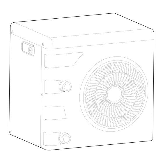
POOL MINI HEAT PUMP 14800BTU
ITEM #
75219
OWNER'S MANUAL AND SAFETY INSTRUCTIONS
SAVE THIS MANUAL. KEEP THIS MANUAL FOR SAFETY WARNINGS, PRECAUTIONS, ASSEMBLY,
OPERATION, INSPECTION, MAINTENANCE AND CLEANING PROCEDURES. WRITE THE PRODUCT'S
SERIAL NUMBER ON THE BACK OF THE MANUAL, OR THE MONTH AND YEAR OF PURCHASE IF
PRODUCT HAS NO SERIAL NUMBER
FOR QUESTIONS, PLEASE CALL CUSTOMER SERVICE: 909.628.0880
Advertisement

Related Manuals for XtremepowerUS 75219


Summary of Contents for XtremepowerUS 75219
- Page 1 POOL MINI HEAT PUMP 14800BTU ITEM # 75219 OWNER’S MANUAL AND SAFETY INSTRUCTIONS SAVE THIS MANUAL. KEEP THIS MANUAL FOR SAFETY WARNINGS, PRECAUTIONS, ASSEMBLY, OPERATION, INSPECTION, MAINTENANCE AND CLEANING PROCEDURES. WRITE THE PRODUCT’S SERIAL NUMBER ON THE BACK OF THE MANUAL, OR THE MONTH AND YEAR OF PURCHASE IF PRODUCT HAS NO SERIAL NUMBER FOR QUESTIONS, PLEASE CALL CUSTOMER SERVICE: 909.628.0880...
- Page 2 -Section of the cable; This section is indicative and should be checked and adapted according to the needs and conditions of use. -The tolerance of acceptable voltage variation is +/- 10% during operation. The connections must be dimensioned according to the power of the device and the state of installation. 12AWG 10AWG 8AWG 6AWG 75219 ≮ 12A...
- Page 3 • This manual includes all necessary information for the use and installation of the heat pump. • Read this manual thoroughly and make sure you understand and familiarize yourself with the installation and operation of the heat pump. • The installer of the heat pump is responsible for the installation of the product and should follow the manufacturer's instructions and the regulations.
- Page 4 1.2" - 1.5" (2pcs) 4.92 FT installed...
- Page 6 HEATING DEFROSTING ERROR PRACTICAL VALUE ! 。 ℉ SET VALUE WATER TEMPERATURE ! 。 ℉ 4. Press to check the CT when the heat pump is running . 5. That the icon is flashing means preparing to work , and that the icon is lighting means working . 6.
- Page 7 1 3/4 FT...
- Page 10 DIGI CONTROLLER 110V 10 11 12 12V/AC T R A N S - F O R M E R defrost units ( ) optional ( ) Electrical Supply: YLW/GRN (110V)...
- Page 11 75219 15000 0.75 13500 0.75 115V 10.6 1.25-1.5 15x12x15 18x16x17...
- Page 12 NO water flow Check pump or others E3 displaying...
-
Page 14: Please Read The Following Carefully
DISCLAIMER PLEASE READ THE FOLLOWING CAREFULLY THE MANUFACTURER AND/OR DISTRIBUTOR HAS PROVIDED THE PARTS LIST AND ASSEMBLY DIAGRAM IN THIS MANUAL AS A REFERENCE TOOL ONLY. NEITHER THE MANUFACTURER OR DISTRIBUTOR MAKES ANY REPRESENTATION OR WARRANTY OF ANY KIND TO THE BUYER THAT HE OR SHE IS QUALIFIED TO MAKE ANY REPAIRS TO THE PRODUCT, OR THAT HE OR SHE IS QUALIFIED TO REPLACE ANY PARTS OF THE PRODUCT.
Need help?
Do you have a question about the 75219 and is the answer not in the manual?
Questions and answers