Advertisement
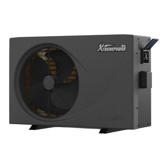
'RENEPOIIIER
SWIMMING POOL HEAT PUMP
ITEM# 75217
OWNER'S MANUAL AND SAFETY INSTRUCTIONS
SAVE THIS MANUAL. KEEP THIS MANUAL FOR SAFETY WARNINGS. PRECAUTIONS. ASSEMBLY.
OPERATION. INSPECTION. MAINTENANCE AND CLEANING PROCEDURES. WRITE THE PRODUCT'S
SERIAL NUMBER ON THE BACK OF THE MANUAL, OR THE MONTH AND YEAR OF PURCHASE IF
PRODUCT HAS NO SERIAL NUMBER
FOR QUESTIONS, PLEASE CALL CUSTOMER SERVICE: 909.628.0880
Advertisement
Table of Contents

Summary of Contents for XtremepowerUS 75217
- Page 1 'RENEPOIIIER SWIMMING POOL HEAT PUMP ITEM# 75217 OWNER'S MANUAL AND SAFETY INSTRUCTIONS SAVE THIS MANUAL. KEEP THIS MANUAL FOR SAFETY WARNINGS. PRECAUTIONS. ASSEMBLY. OPERATION. INSPECTION. MAINTENANCE AND CLEANING PROCEDURES. WRITE THE PRODUCT'S SERIAL NUMBER ON THE BACK OF THE MANUAL, OR THE MONTH AND YEAR OF PURCHASE IF PRODUCT HAS NO SERIAL NUMBER FOR QUESTIONS, PLEASE CALL CUSTOMER SERVICE: 909.628.0880...
- Page 2 The Swimming Pool Heat Pump Unit is intended to heat the swimming pool water and regulate the temperature. Use in any other application will void the warranty. The inlet & outlet connections cannot support any load from another piping system. Make certain the air outlet is not directed towards any person, animal, or vegetation.
- Page 3 Note: There may be variations in values due to climatic conditions.
-
Page 4: Electric Wiring Diagram
Diagram for Water Piping Connections WATER TO SWIMMING POOL THREE WAY VALVE STOP VALVE SWIMMING POOL WATER Pump TREATMENT SYSTEM STOP VALVE THREE WAY VALVE POOL WATER Note: The diagram is for demonstration purposes only, and layout of the pipes is for reference only. -
Page 5: Installation
Protecting devices and cable specification Breaker Rated Current : 20 A Breaker Rated Residual Action Current : 30 mA Fuse : 25 A Power Cord (AWG) : 3X12 Signal Cable (AWG) : 3X20 Note: The above data is for an electrical cord of less than 10 m. If electrical cord is > 10 m, wire diameter must be increased. - Page 6 The piping sequence is as follows: pool > pool pump > filter > heat pump > check valve > chemical feeder pool. Automated chlorine distribution systems, if used, must be placed downstream of the heat pump to minimize harm to the pool equipment. Use rigid PVC piping if possible (SCH40 or SCH80).
- Page 7 Set the operation parameter: ◎ When the unit powered up but not running, long Press “ ” button 3S to enter operation parameter setting interface. ◎ Press " " to check parameter(parameter from P01-P14, see Operation Parameter Table). ◎ Under parameter, press " "...
- Page 8 Auto mode setting water temperature 50~113°F 79°F Compressor protection Exhaust temperature 185~230°F 203°F Low ambient temperature protection -4~50°F 5°F EEV manual step number 18~94 Check system current status Press “ ” button 3S to enter check system current status interface. Remarks Meaning Range...
-
Page 9: Real-Time Clock Setting
Real-time clock setting Press “ " + “ ” button 3S to set clock, “ " symbol will flash during this setting, Press " " button, it will enter hour setting, press “ ” buttons to change the value. ” or “ Press "... -
Page 10: Inspection Before Use
TESTING Inspection before use o Check installation of the whole machine and the pipe connections according to the pipe connection diagram o Check the electric wiring according to the electric wiring diagram; and make sure the Heat Pump is bonded o Make sure that the main machine power switch is off o Check the temperature setting. -
Page 11: Troubleshooting
Disconnect power supply of the heat pump before any examination and repair. The unit must always be powered off before opening the access panel. Always cut off the unit’s main power whenever the access panel is open or removed. In winter seasons, please drain water clear of the machine, disconnect power Supply to prevent any machine damage, and cover the machine body with plastic cover to avoid dust. - Page 12 TROUBLESHOOTING b) This table explains the error codes caused by a defective regulating component. Displ Problem Cause Solution “WATER IN” sensor out of Sensor open or short-circuited Check or replace the sensor order “Compressor exhust” Sensor open or short-circuited Check or replace the sensor sensor out of order “HEATING COIL PIPE”...
-
Page 14: Please Read The Following Carefully
Note: Some parts are listed and shown for illustration purposes only and are not available individually as replacement parts. or warranties with respect to this manual or with respect to the products described herein. XtremePowerUS shall not be MADE IN CHINA...


Need help?
Do you have a question about the 75217 and is the answer not in the manual?
Questions and answers