
Subscribe to Our Youtube Channel
Related Manuals for Unitronics UMD-B5

Summary of Contents for Unitronics UMD-B5
- Page 1 Unitronics UMD-B5 User Guide DRIVE MODEL: UMD-XXXXX-B5 V1.01 Document Version: V1.01 (Sept. 2024)
-
Page 2: About This Manual
Purpose This manual provides the information required for the Selection, Wiring, Connection, Settings, Trial Operation, Tuning and Functions of the UMD-B5 Series AC Servo Drive with CANopen communication or pulse references. Read and understand this manual to ensure correct usage of the product. - Page 3 UMD-B5 CANopen User Guide About this Manual Abbreviation Meaning FMMU Fieldbus Memory Management Unit FPRD Configured Address Physical Read FPWR Configured Address Physical Write FPRW Configured Address Physical ReadWrite FRMW Configured Address Physical Read Multiple Write Logical memory Read Logical memory Write...
-
Page 4: Symbols
UMD-B5 CANopen User Guide About this Manual Symbols The symbols that may be found in this document are defined as follows. Symbol Description Indicates a hazard with a high level of risk that, if not avoided, will result in death or serious injury. -
Page 5: Safety Precautions
UMD-B5 CANopen User Guide Safety Precautions Safety Precautions General Precautions Never remove covers, cables, connectors, or optional devices while ◼ power is being supplied to the Drive. Never connect a three-phase power supply to the terminals U, V, and W ◼... -
Page 6: Storage Precautions
UMD-B5 CANopen User Guide Safety Precautions Storage Precautions Follow all instructions on the packages, and never place an excessive load ◼ on the product during storage. Never install or store the product in any of the following locations: ◼ -- locations that are subject to direct sunlight. -
Page 7: Operation Precautions
UMD-B5 CANopen User Guide Safety Precautions Operation Precautions In order to prevent accidents, please test the Motor with no load (not ◼ connected to the Drive shaft). When starting to operate on the supporting machine, set the user parameters ◼... -
Page 8: Table Of Contents
Wiring Precautions ........................... v Operation Precautions ........................vi Maintenance Precautions ........................ vi Disposal Precautions ........................vi Chapter 1 UMD-B5 Servo Drive ......................1 1.1 Product Features ........................1 1.2 Interpreting the Nameplate ......................2 1.3 Model Designations ........................3 1.4 Part Names ..........................4 1.5 Ratings and Specifications ....................... - Page 9 UMD-B5 CANopen User Guide Contents 5.13 PCP Control ......................... 115 5.14 Selection of Control Mode Combinations ................122 5.15 Torque Limit........................... 125 5.16 Homing ..........................129 5.17 Other Output Signals ......................135 Chapter 6 CANopen Communication ....................137 6.1 Position Control Function ....................137 6.2 HOMING MODE ........................
-
Page 10: Chapter 1 Umd-B5 Servo Drive
Chapter 1 UMD-B5 Servo Drive 1.1 Product Features The UMD-B5 servo drive is designed with its excellent performance and practical control functions to create a complete set of solutions with the best cost performance for customers. Matching with the UMM-B5 and UMM-B6 servo motors, compatible with Unitronics PLCs, it offers high-speed, high-precision, and high-performance machine solutions. -
Page 11: Interpreting The Nameplate
UMD-B5 CANopen User Guide Chapter 1 UMD Servo Drive 1.2 Interpreting the Nameplate Rated Output Rated Input Model Serial Number Document Version: V1.01 (Sept. 2024) 2024 Unitronics All Rights Reserved... -
Page 12: Model Designations
UMD-B5 CANopen User Guide Chapter 1 UMD Servo Drive 1.3 Model Designations 0002 Product Input Output Power Family Voltage Sign Spec. Sign Spec. 0000 0.05 kW 200-240V,1 Ph 0001 0.1 kW 200-240V,1/3 Ph 0002 0.2 kW 0004 0.4 kW 200-240V,3 Ph 0007 0.75 kW... -
Page 13: Part Names
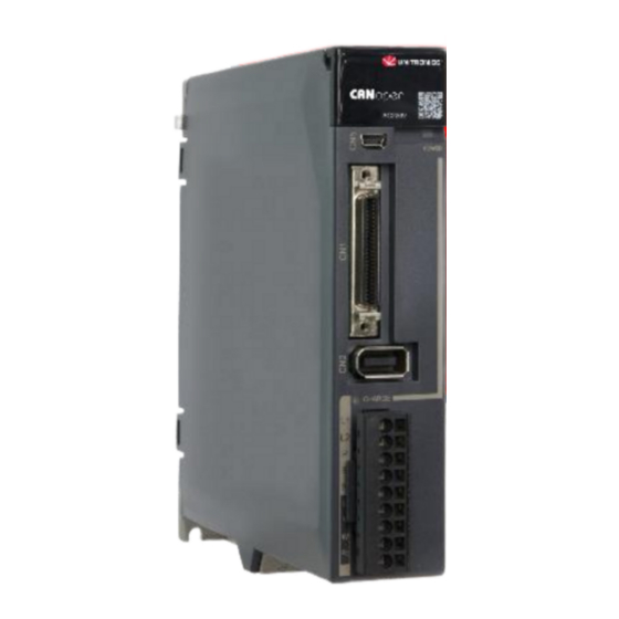
UMD-B5 CANopen User Guide Chapter 1 UMD Servo Drive 1.4 Part Names 200VAC Rated power from 50W to 400W Name Description Panel Operator A module for Servo status displays and parameter settings USB Connector Computer connector IO Signal Connector Connects to sequence I/O signals... - Page 14 UMD-B5 CANopen User Guide Chapter 1 UMD Servo Drive Name Description Lit while the main circuit power is being supplied Note: CHARGE Indicator Lamp Even if you turn OFF the main circuit power supply, this indicator will be lit as long as the internal capacitor remains charged. Never touch the main circuit or Motor terminals while this indicator is lit, in case the electric shock.
- Page 15 UMD-B5 CANopen User Guide Chapter 1 UMD Servo Drive Name Description Lit while the main circuit power is being supplied Note: CHARGE Indicator Lamp Even if you turn OFF the main circuit power supply, this indicator will be lit as long as the internal capacitor remains charged. Never touch the main circuit or Motor terminals while this indicator is lit, in case the electric shock.
- Page 16 UMD-B5 CANopen User Guide Chapter 1 UMD Servo Drive 400VAC, rated power from 1kW to 5kW NOTE The figure above shows an example of a product with a rated power of 1kW to 1.5kW. Products with a rated power of 2kW~3kW are similar in appearance and have the same components.
- Page 17 UMD-B5 CANopen User Guide Chapter 1 UMD Servo Drive Name Description POWER Indicator Lamp Light up when the control circuit is powered on. IO Signal Connection Port Socket for IO signal connectors. Encoder Connection Port Socket for the encoder connectors of the motor.
- Page 18 UMD-B5 CANopen User Guide Chapter 1 UMD Servo Drive Name Description Lights up when the main circuit is powered on. Note: CHARGE Indicator Lamp If voltage remains in the capacitors inside the drive after the main circuit has been switched off, and the indicator lamp will be ON, do not touch the main circuit and motor terminals at this time to avoid electric shock.
-
Page 19: Ratings And Specifications
UMD-B5 CANopen User Guide Chapter 1 UMD Servo Drive 1.5 Ratings and Specifications Drive Model: UMD- 0000B 0001B 0002B 0004B 0007CU 0010CU 0015CU 0020C Continuous Output Current [Arms] 12.6 Instantaneous Maximum Output Current [Arms] 11.5 19.5 21.0 31.6 Single-phase -... - Page 20 UMD-B5 CANopen User Guide Chapter 1 UMD Servo Drive Mounting Base-mounted Speed Control Range 1:5000 ±0.01% of rated speed max. (For a load fluctuation of 0% to 100%) Coefficient of Speed 0% of rated speed max. (For a load fluctuation of ±10%)
- Page 21 UMD-B5 CANopen User Guide Chapter 1 UMD Servo Drive Limit). Except TP1 and TP2, a signal can be allocated, and the positive and negative logic can be changed. Allowable voltage range: 5 VDC to 30 VDC Number of output points: 4 (1 of them fixed for Servo Alarm)
-
Page 22: External Dimensions
UMD-B5 CANopen User Guide Chapter 1 UMD Servo Drive 1.6 External Dimensions Models Grounding H(mm) W(mm) D(mm) Connectors(mm) Terminals 0000B-0004B 2XM4 0007CU-0010CU 2XM4 0015CU-0020C 2XM4 0010E-0015E 2XM4 0020E-0030E 2XM4 0050E-0075E 2XM4 Document Version: V1.01 (Sept. 2024) 2024 Unitronics All Rights Reserved... -
Page 23: System Configuration
UMD-B5 CANopen User Guide Chapter 1 UMD Servo Drive 1.7 System Configuration 200VAC Rated power from 50W to 400W Document Version: V1.01 (Sept. 2024) 2024 Unitronics All Rights Reserved... - Page 24 UMD-B5 CANopen User Guide Chapter 1 UMD Servo Drive 200VAC, Rated power from 750W to 2kW Document Version: V1.01 (Sept. 2024) 2024 Unitronics All Rights Reserved...
- Page 25 UMD-B5 CANopen User Guide Chapter 1 UMD Servo Drive 400VAC,Rated power from:1kW~7.5kW Document Version: V1.01 (Sept. 2024) 2024 Unitronics All Rights Reserved...
- Page 26 UMD-B5 CANopen User Guide Chapter 1 UMD Servo Drive Specifications of the Basic Peripherals Min. value of Spec. of built-in Min. rated current external Model Main circuit voltage regenerative of the circuit regeneration resistor breaker resistor UMD-0000B-B5 Single-phase AC 200V~240V -...
- Page 27 UMD-B5 CANopen User Guide Chapter 1 UMD Servo Drive Drive model Power Motor model Encoder cable Power cable UMM-0000BA-B5 UMD-0000B-B5 UMM-0000BAB-B5 UMM-0001BA-B5 UMD-0001B-B5 100W UMM-0001BAB-B5 UMC-B5A-PN-(03/05/10) (No Brake) UMM-0002BA-B5 UMC-B5A-PB-(03/05/10) (With Brake) UMD-0002B-B5 200W UMM-0002BAB-B5 UMC-B5-FA-(03/05/10) UMM-0004BA-B5 UMD-0004B-B5 400W UMM-0004BAB-B5...
-
Page 28: Chapter 2 Installation
UMD-B5 CANopen User Guide Chapter 2 Installation Chapter 2 Installation 2.1 Installation Precautions Installation Near Sources of Heat ⚫ Implement measures to prevent temperature increases caused by external heat sources so that the ambient temperature of the Drive is within the specified limits. -
Page 29: Mounting Hole Dimensions
UMD-B5 CANopen User Guide Chapter 2 Installation 2.3 Mounting Hole Dimensions Use all mounting holes to securely mount the Drive to the mounting surface. To mount the Drive, use a screwdriver that is longer than the depth of the Drive. -
Page 30: Mounting Interval
UMD-B5 CANopen User Guide Chapter 2 Installation 2.4 Mounting Interval Installing One Drive in a Control Cabinet When installing a single Drive use Figure 2-2 as a reference for free space around the installation. Figure 2-2 Installing a single Drive in a control cabinet... - Page 31 Installing multiple Drives in a control cabinet NOTE The UMD-B5 allows close mounting of 1mm between two adjacent drives. The UMD-0050EU-B5 and UMD-0075EU-B5 drives do not allow close mounting due to wiring, and the distance between drives is to be confirmed upon assembly of the cable, for which 80mm is recommended.
-
Page 32: Chapter 3 Wiring And Connecting
UMD-B5 CANopen User Guide Chapter 3 Wiring and Connecting Chapter 3 Wiring and Connecting 3.1 Precautions for Wiring 3.1.1 General Precautions Never change any wiring while power is being supplied, in case a risk of electric shock or injury. DANGER Wiring and inspections must be performed only by qualified engineers. -
Page 33: Countermeasures Against Noise
UMD-B5 CANopen User Guide Chapter 3 Wiring and Connecting Use a molded-case circuit breaker or fuse to protect the main circuit. ◼ The Drive connects directly to a commercial power supply; it is not isolated through a transformer or other device. Always use a molded-case circuit breaker or fuse to protect the Servo System from accidents involving different power system voltages or other accidents. - Page 34 UMD-B5 CANopen User Guide Chapter 3 Wiring and Connecting Wiring example for countermeasures against noise Drive Motor Noise Filter 200 VAC 2.0 mm min. 2.0 mm min. Operation relay sequence User signal generators Noise Filter Power supply 2.0 mm min.
- Page 35 UMD-B5 CANopen User Guide Chapter 3 Wiring and Connecting Separate the Noise Filter ground wire from the output lines. Do not place the Noise Filter ⚫ ground wire, output lines, and other signal lines in the same duct or bundle them together.
-
Page 36: Cable Fixing
UMD-B5 CANopen User Guide Chapter 3 Wiring and Connecting 3.1.3 Grounding Implement grounding measures as described in this section. Implementing suitable grounding measures will also help prevent malfunctions, which can be caused by noise. Always use an unpainted backplane for electrical cabinets. -
Page 37: Basic Wiring Diagrams
UMD-B5 CANopen User Guide Chapter 3 Wiring and Connecting 3.2 Basic Wiring Diagrams Rated power from 50W to 400W Document Version: V1.01 (Sept. 2024) 2024 Unitronics All Rights Reserved... - Page 38 UMD-B5 CANopen User Guide Chapter 3 Wiring and Connecting Rated power from 750W to 2kW Document Version: V1.01 (Sept. 2024) 2024 Unitronics All Rights Reserved...
- Page 39 UMD-B5 CANopen User Guide Chapter 3 Wiring and Connecting 400V AC, rated power from 1kW to 7.5kW Document Version: V1.01 (Sept. 2024) 2024 Unitronics All Rights Reserved...
-
Page 40: Terminals Arrangements
UMD-B5 CANopen User Guide Chapter 3 Wiring and Connecting 3.3 Terminals Arrangements Rated power from 50W to 400W Document Version: V1.01 (Sept. 2024) 2024 Unitronics All Rights Reserved... - Page 41 UMD-B5 CANopen User Guide Chapter 3 Wiring and Connecting 200VAC, rated power from 750W to 2kW Document Version: V1.01 (Sept. 2024) 2024 Unitronics All Rights Reserved...
- Page 42 UMD-B5 CANopen User Guide Chapter 3 Wiring and Connecting 400VAC, rated power from 1kW to 1.5kW Document Version: V1.01 (Sept. 2024) 2024 Unitronics All Rights Reserved...
- Page 43 UMD-B5 CANopen User Guide Chapter 3 Wiring and Connecting 400VAC, rated power from 2kW to 3kW Document Version: V1.01 (Sept. 2024) 2024 Unitronics All Rights Reserved...
- Page 44 UMD-B5 CANopen User Guide Chapter 3 Wiring and Connecting 400VAC, rated power from 5kW to 7.5kW Document Version: V1.01 (Sept. 2024) 2024 Unitronics All Rights Reserved...
-
Page 45: Wiring The Power Supply To Drive
UMD-B5 CANopen User Guide Chapter 3 Wiring and Connecting 3.4 Wiring the Power Supply to Drive 3.4.1 Terminals Arrangement Rated power from 50W to 400W Symbols Name Specifications and Reference Main circuit power Single-phase, 200 VAC to 240 VAC, -15% to +10%, L1、L2... - Page 46 UMD-B5 CANopen User Guide Chapter 3 Wiring and Connecting Rated power from 750W to 2kW Symbols Name Specifications and Reference Main circuit power Three-phase, 200 VAC to 240 VAC, -15% to +10%, L1、L2、L3 supply input terminals 50Hz or 60Hz For using a DC reactor, remove the short wiring, and DC reactor terminals ⊕1、⊕2...
- Page 47 UMD-B5 CANopen User Guide Chapter 3 Wiring and Connecting 400VAC, rated power from 1kW to 3kW Take for example a product with a power rating of 1kW~1.5kW. Products with power rating from 1.5kW to 3kW are similar in appearance and have the same components...
- Page 48 UMD-B5 CANopen User Guide Chapter 3 Wiring and Connecting 400VAC, rated power from 5kW to 7.5kW Symbols Name Specifications Power supply input L1, L2, L3 3-phase 380V~4 V, -15%~+10%, 50Hz/60Hz terminals DC busbar connectors When multiple servo drives are used in a common DC bus configuration, ⊕...
-
Page 49: Minimum Value
UMD-B5 CANopen User Guide Chapter 3 Wiring and Connecting 3.4.2 Wiring a Regenerative Resistor Connection Diver model Rated power Minimum value terminals UMD-0000B-B5 UMD-0001B-B5 100W 45Ω P、B UMD-0002B-B5 200W UMD-0004B-B5 400W UMD-0007CU-B5 750W 25Ω B1、B2 UMD-0010CU-B5 UMD-0015CU-B5 1.5kW 10Ω B1、B2C... - Page 50 UMD-B5 CANopen User Guide Chapter 3 Wiring and Connecting Connect the external regenerative resistor as follows to avoid damaging the drive or malfunction. It is necessary to connect an external regenerative resistor for the drives rated ◼ power from 50W to 400W. The minimum resistance value of the external regenerative resistor is 45 ohms.
-
Page 51: Wiring Procedure
UMD-B5 CANopen User Guide Chapter 3 Wiring and Connecting 3.4.3 Wiring Procedure Prepare the following items before preparing the wiring for the Main Circuit Terminals and Control Circuit Terminals. Required Item Description Flat-blade screwdriver: commercially available screwdriver ⚫ Flat-blade screwdriver or with tip width of 3.0 mm to 3.5 mm... - Page 52 UMD-B5 CANopen User Guide Chapter 3 Wiring and Connecting Step 4 Crimp the cable that has been inserted into the ferrule, and cut off the cable conductor portion protruding from the ferrule (The allowable protruding length after cutting should not be more than 0.5 mm).
- Page 53 UMD-B5 CANopen User Guide Chapter 3 Wiring and Connecting 3.4.4 Motor Connection Diagram Document Version: V1.01 (Sept. 2024) 2024 Unitronics All Rights Reserved...
- Page 54 UMD-B5 CANopen User Guide Chapter 3 Wiring and Connecting 3.4.5 Power Input Wiring Example Rated power from 50W to 400W Use single-phase 200 VAC to 240 VAC as the power input for the Drives rated power from 50W to 400W.
- Page 55 UMD-B5 CANopen User Guide Chapter 3 Wiring and Connecting Rated power from 750W to 2kW Use single-phase or three-phase 200 VAC to 240 VAC as the power input for the Drives rated power from 750W to 2kW. The following figure shows the wiring example for using the three-phase AC input power.
- Page 56 UMD-B5 CANopen User Guide Chapter 3 Wiring and Connecting The following figure shows the wiring example for using the single-phase AC input power. Document Version: V1.01 (Sept. 2024) 2024 Unitronics All Rights Reserved...
- Page 57 UMD-B5 CANopen User Guide Chapter 3 Wiring and Connecting 400VAC, rated power from 1kW to 5kW Use a three-phase AC 380V~480V as the power input for the drives. [When using three-phase AC power supply] Document Version: V1.01 (Sept. 2024) 2024 Unitronics All Rights Reserved...
-
Page 58: Wiring The Encoder
UMD-B5 CANopen User Guide Chapter 3 Wiring and Connecting 3.5 Wiring the Encoder 3.5.1 Connection Diagram 3.5.2 Battery Case Connection Absolute encoders require a battery supply to retain the absolute encoder ◼ data when the Drive power is removed. Battery model: LS 14500 (3.6V, AA) ◼... - Page 59 UMD-B5 CANopen User Guide Chapter 3 Wiring and Connecting Absolute encoder cable Drive connector Mount a lithium battery Step 4 Close the cover of the battery case. Step 5 Repower up the Drive. Step 6 Reset the Alarms. NOTE Perform the Fn011 and Fn010 by Panel Operator to reset the alarms, for details, see the section ⚫...
-
Page 60: I/O Signal Connections
UMD-B5 CANopen User Guide Chapter 3 Wiring and Connecting 3.6 I/O Signal Connections 3.6.1 Signal Diagram NOTE The signal definitions for the IO signals of all drives are the same. The signal name in the diagram above is predefined at the factory. You can assign the following signals by Pn509, Pn510, and Pn511, see the section 5.7 IO Signal Allocation... - Page 61 UMD-B5 CANopen User Guide Chapter 3 Wiring and Connecting Name Type Function COIN+ Output Positioning completed: ON after positioning is completed (deviation pulse reaches the set value). COIN- Output I/O signal power supply, to be supplied by user with a DC 24V power supply.
-
Page 62: Wiring Description
UMD-B5 CANopen User Guide Chapter 3 Wiring and Connecting Name Type Function CCW+CW ⚫ SIGN+ Input Two-phase orthogonal pulse (90ºphase difference) ⚫ SIGN- Input Power supply for open collector command (2KΩ/0.5W Input resistor is preset inside of the servo drive) - Page 63 UMD-B5 CANopen User Guide Chapter 3 Wiring and Connecting Output Signals Wiring Taking the output signal TGON as an example, Figure 3-3 shows the connection diagram for using the optocoupler or relay, and the wiring of other output signals wiring is the same as it.
- Page 64 UMD-B5 CANopen User Guide Chapter 3 Wiring and Connecting Figure 3-4 Holding brake wiring diagram Drive Motor Single-phase Noise 220 VAC filter +24V Brake control relay (brake power supply) 3.6.5 Touch Probe Wiring You shall only use the terminals CN1-18 (TP1) and CN1-19 (TP2) for Touch Probe input signal, which has been allocated at factory.
-
Page 65: Usb Communication Cable
Connection Diagram Cable Description You can purchase the USB Communication Cable provided by UNITRONICS “USB2-CAB200”, or you can purchase the commercially available products yourself. The plug connected to your PC is USB Type-A, and the plug connected to the Drive is Mini USB Type-B. -
Page 66: Chapter 4 Basic Settings
UMD-B5 CANopen User Guide Chapter 4 Basic Settings Chapter 4 Basic Settings You can implement the functions of parameter setting, display, monitoring, alarm, adjustment, etc. of the Drive in the following two ways. Use the Panel Operator of the Drive. -
Page 67: Basic Mode Selection
UMD-B5 CANopen User Guide Chapter 4 Basic Settings 4.1.2 Basic Mode Selection The basic modes include: Status Display Mode, Parameter Setting Mode, Utility Function Mode, and Monitor Mode. Select a basic mode with [M] key to display the operation status, set parameters and operation references, as is shown in Figure 4-2. - Page 68 UMD-B5 CANopen User Guide Chapter 4 Basic Settings Table 4-1 Display meaning of each segment on Bit Data Speed Control/Torque Control Position Control Mode Meaning Description Meaning Description Lit when the difference between the Motor speed and reference Lit if the error between position...
-
Page 69: Display Information
UMD-B5 CANopen User Guide Chapter 4 Basic Settings Display information Description Alarm Number Display NOTE: When the Drive is in Servo Alarm State, you shall check and correct the fault according to the Alarm Number Display, and then, you can press [◄] key to try to clear the current alarm. -
Page 70: Parameter Setting Mode
UMD-B5 CANopen User Guide Chapter 4 Basic Settings 4.1.4 Parameter Setting Mode Functions can be selected or adjusted by setting parameters. There are two types of parameters. ⚫ Function Parameters: the functions allocated to each digit of the Panel Operator can be selected. - Page 71 UMD-B5 CANopen User Guide Chapter 4 Basic Settings After completing the function parameters setting, restart the Drive to take effect. ----End Document Version: V1.01 (Sept. 2024) 2024 Unitronics All Rights Reserved...
- Page 72 UMD-B5 CANopen User Guide Chapter 4 Basic Settings Adjustment Parameters Setting The example below shows how to change parameter Pn102 (Speed Loop Gain) from 100 to 85. Step 1 Press [M] key several times to select the Parameter Setting Mode.
- Page 73 UMD-B5 CANopen User Guide Chapter 4 Basic Settings Step 10 Press [◄] key twice, moving the flashing decimal point to the 3rd digit. Step 11 Press [▲] key twice, changing the value of the 3rd digit from 0 to 2.
-
Page 74: Monitor Mode
UMD-B5 CANopen User Guide Chapter 4 Basic Settings 4.1.5 Monitor Mode The Monitor Mode can be used for monitoring the reference values, I/O signal status, and Drive internal status. The Monitor Mode can be selected during Motor operation. Select Monitor Mode The example below shows how to display, the contents of monitor number Un003 (when the Motor rotates at 100 ). - Page 75 UMD-B5 CANopen User Guide Chapter 4 Basic Settings Monitor Number Content of Display Unit Un022 Main board temperature ℃ Un024 PCP target position - The status (low level or high level) of input signal allocated to each input terminal is displayed.
-
Page 76: Utility Function Mode
UMD-B5 CANopen User Guide Chapter 4 Basic Settings 4.1.6 Utility Function Mode This section describes how to apply the basic operations using the Panel Operator to run and adjust the Motor. The following table shows the parameters in the Utility Function Mode. - Page 77 UMD-B5 CANopen User Guide Chapter 4 Basic Settings Fn000 (Alarm trace data display) The alarm trace data display can display up to ten previously occurred alarms. The following are the steps to display the alarm trace data. Step 1 Press [M] key several times to select the Utility Function Mode.
- Page 78 Reference Offset. Fn005 (Automatic offset-adjustment of Motor current detection signal) Motor current detection offset adjustment has been performed at UNITRONICS before shipping. Basically, the user need not perform this adjustment. Execute the automatic offset adjustment if the torque ripple is too big ◼...
- Page 79 UMD-B5 CANopen User Guide Chapter 4 Basic Settings Fn006 (Manual offset-adjustment of Motor current detection signal) To adjust the offset, perform the automatic adjustment (Fn005) first. And if the torque ripple is still big after the automatic adjustment, perform the manual offset-adjustment as follows.
- Page 80 UMD-B5 CANopen User Guide Chapter 4 Basic Settings Fn007 (Software version display) The following are the steps to display the software versions. Step 1 Press [M] key several times to select the Utility Function Mode. Step 2 Press [▲] key or [▼] key to select the function number Fn007.
- Page 81 UMD-B5 CANopen User Guide Chapter 4 Basic Settings Fn011 (Absolute encoder alarm reset) The following are the steps to reset the absolute encoder alarm. Step 1 Press [M] key several times to select the Utility Function Mode. Step 2 Press [▲] key or [▼] key to select the function number Fn011.
-
Page 82: Chapter 5 Application Functions
UMD-B5 CANopen User Guide Chapter 5 Application Functions Chapter 5 Application Functions 5.1 Power Supply The main circuit and control circuit of the Drive can be operated with AC power input. When AC power input is selected, single- phase or three phase power input can be used. You shall set the parameter Pn007.1 and Pn007.3 (use AC power input) according to the applicable power supply. -
Page 83: Motor Rotation Direction
UMD-B5 CANopen User Guide Chapter 5 Application Functions 5.2 Motor Rotation Direction You can reverse the direction of Motor rotation by changing the setting of Pn001.0. The default setting for Forward Rotation is counterclockwise (CCW) as viewed from the Drive end. - Page 84 UMD-B5 CANopen User Guide Chapter 5 Application Functions Figure 5-1 Wiring diagram for the overtravel Motor forward direction Drive Motor Limit Limit N-OT switch switch P-OT Using the overtravel function is not necessary for rotating applications such as rotary tables and conveyors. No wiring for overtravel input signals is required.
-
Page 85: Motor Stopping Methods
UMD-B5 CANopen User Guide Chapter 5 Application Functions 5.4 Motor Stopping Methods Following 4 ways are available to stop the drive alarming (Gr.1 or Gr.2), OT state, and servo OFF occurs: Stop method Meaning Stopping by dynamic The electric circuits are internally connected to stop the Motor quickly. -
Page 86: Holding Brake
UMD-B5 CANopen User Guide Chapter 5 Application Functions 5.4.3 Motor Stop Methods for Gr.2 Alarms You can select the Motor stopping methods for Gr.2 Alarms occur by setting the parameter Pn004.0. When Parameter Setting Stop Method After Stopping Enabled 0 [Default]... - Page 87 UMD-B5 CANopen User Guide Chapter 5 Application Functions The brake built into a Motor with a Brake is a de-energization brake. It is used only to hold the Motor and cannot be used for braking. Use the holding brake only to hold a Motor that is already stopped.
-
Page 88: Brake Operating Sequence
UMD-B5 CANopen User Guide Chapter 5 Application Functions 5.5.2 Brake Operating Sequence You must consider the time required to release the brake and the time required to brake to determine the brake operation timing, as described below. Servo ON command... - Page 89 UMD-B5 CANopen User Guide Chapter 5 Application Functions The /BK signal is not allocated in default setting, set its allocation in Pn511. Parameter Setting + Pin - Pin Meaning The /BK signal is output from output Pn511.0 CN1-11 CN1-12 terminal CN1-11 and CN1-12.
- Page 90 UMD-B5 CANopen User Guide Chapter 5 Application Functions When Parameter Name Range Unit Default Enabled Pn505 Servo ON Waiting Time -2000 to 2000 Immediately Pn506 Servo OFF Waiting Time 0 to 500 10ms Immediately NOTE Set Pn505 as a positive value, when S-ON command is received, the /BK signal will be output first, ⚫...
-
Page 91: Encoder Settings
UMD-B5 CANopen User Guide Chapter 5 Application Functions 5.6 Encoder Settings 5.6.1 Absolute Encoder Selection Absolute encoders are fitted on motors with all the motors series (B5/B6) . Those encoders require a battery supply to retain the absolute encoder data when the Drive power is removed. - Page 92 UMD-B5 CANopen User Guide Chapter 5 Application Functions The relationship between the number of turntable revolutions and the number of motor revolutions is shown in the following figure. Number of table rotation Multiturn data Pn228-1 Number of rotations When Parameter...
- Page 93 UMD-B5 CANopen User Guide Chapter 5 Application Functions Drive Host controller Note: Even in the reverse mode (Pn001.0=1), the pulse dividing output phase form is the same as the standard setting (Pn001.0=0). Output Phase Form Forward rotation or movement Reverse rotation or movement (phase B leads by 90°)
-
Page 94: Io Signal Allocation
UMD-B5 CANopen User Guide Chapter 5 Application Functions 5.7 IO Signal Allocation Functions are allocated to the pins on the I/O signal connector (CN1) in advance. You can change the allocations and the polarity for some of the connector pins. Function allocations and polarity settings are made with parameters. - Page 95 UMD-B5 CANopen User Guide Chapter 5 Application Functions Signal Name Value P-OT Forward Drive Prohibit Input Signal N-OT Reverse Drive Prohibit Input Signal ALMRST Alarm Clear Clear Position Deviation Pulse P-CL Forward External Torque Limit Input Signal N-CL Reverse External Torque Limit Input Signal...
-
Page 96: Output Signal Allocations
UMD-B5 CANopen User Guide Chapter 5 Application Functions 5.7.2 Output Signal Allocations Allocation Description The I/O signal connector (CN1) on the Drive provides three group of pins (points) for allocating the output signals, corresponding to the parameter Pn511, as is shown in Figure 5-3. -
Page 97: Control Mode Selection
UMD-B5 CANopen User Guide Chapter 5 Application Functions 5.8 Control Mode Selection Speed control, position control and torque control are available to servo drive. Set through the control mode selection (Pn005.1). Parameter Set Value Control Mode Description Speed Control Controls servomotor speed using analog voltage (Analog Reference) speed reference. - Page 98 UMD-B5 CANopen User Guide Chapter 5 Application Functions Parameter Set Value Control Mode Description Position Control (pulse train Use pulse prohibited function under position reference)↔ control mode. Position Control (pulse prohibited) Pre-set the position control and PJOG operation of 32 program contacts in the servo drive. When...
-
Page 99: Speed Control
UMD-B5 CANopen User Guide Chapter 5 Application Functions 5.9 Speed Control Speed control is selected by Pn005.1: Parameter Setting Meaning When Enabled Pn005.1 Control mode selection: speed control (analog After restart reference) 5.9.1 Setting speed control Speed reference input signal To control the speed of the servo motor at a speed proportional to the input voltage, it is necessary to set the speed reference input signal. - Page 100 UMD-B5 CANopen User Guide Chapter 5 Application Functions Speed Reference Input Example Pn300=150 [factory setting]: Speed Reference Input Direction Motor Speed Forward 150rpm Forward 750rpm -10V Reverse -1500rpm 5.9.2 Adjustment of Speed Reference Offset: When speed control is used, even if the command is 0V (the command speed is 0 or haled), the servo motor may rotate at a slight speed.
- Page 101 UMD-B5 CANopen User Guide Chapter 5 Application Functions Step 5 Press [◄] key and the operating panel is displayed as follows. Step 6 Press [M] key to execute automatic offset adjustment. 2 seconds later Step 7 Press the [◄] key to return to the display of the Fn003.
-
Page 102: Soft Start
UMD-B5 CANopen User Guide Chapter 5 Application Functions Step 7 Press [▲] key or [▼] key to adjust the offset manually. [Note] The adjustment range of the offset is -1024 to 1024. Step 8 Press and hold the [◄] key for 1 second to return to the manual adjustment display. -
Page 103: Zero Clamp Function
UMD-B5 CANopen User Guide Chapter 5 Application Functions Parameter Name Range Unit Default When Enabled Pn306 Soft Start Acceleration Time 0 to 10000 Immediately Pn307 Soft Start Deceleration Time 0 to 10000 Immediately When speed reference uses S-curve (Pn310=1) The figure below shows the timing diagram of the speed reference in the S-curve (Pn310=1). Among them, Pn309 is the time interval for the motor to accelerate from the stop state to the target speed, or the time interval for the motor to decelerate from the target speed to the stop state. - Page 104 UMD-B5 CANopen User Guide Chapter 5 Application Functions The servo motor is fixed within ±1 pulse of the zero clamp effective position. Even if it moves due to external force, it returns to the zero-clamp position. Drive Host Speed controller...
-
Page 105: Position Control
UMD-B5 CANopen User Guide Chapter 5 Application Functions Type Signal Connector Signal State Meaning Name Pin Number ON (low level) Speed coincides. Output /VCMP CN1-11, 12 OFF (high level) Speed does not coincide. [Note] In position control, CN1-11, 12 output /COIN (positioning completion) signal. - Page 106 UMD-B5 CANopen User Guide Chapter 5 Application Functions 5.10.1 Basic Settings of Position Control Setting position reference input form Use Pn004.2 to set the input form of the position reference. Parameter Multiplier Input form Forward Reference Reverse Reference Setting SIGN+...
-
Page 107: Connection Example
UMD-B5 CANopen User Guide Chapter 5 Application Functions Electrical specifications for position reference input Reference Pulse Signal Electrical Specification Remark Form The sign (SIGN) is a t1, t2, t3, t7≤0.1μs SIGN+PULS SIGN PULS forward rotation t4, t5, t6≥3.0μs Max reference frequency:... - Page 108 UMD-B5 CANopen User Guide Chapter 5 Application Functions [Connection Example for Open-Collector Output] Drive Document Version: V1.01 (Sept. 2024) 2024 Unitronics All Rights Reserved...
-
Page 109: Electronic Gear
UMD-B5 CANopen User Guide Chapter 5 Application Functions 5.10.2 Function and Setting of Position Error Clear (/CLR) Signal Allocation of Position Error Clear Signal Type Signal Name Connector Pin Number Meaning Input /CLR CN1-40 Error counter clear When the /CLR signal is set to low level, clear error counter: The error counter inside the servo drive is set to “0”... - Page 110 UMD-B5 CANopen User Guide Chapter 5 Application Functions NOTE Range of electronic gear ratio: 0.01≤electronic gear ratio (B/A)≤100 ⚫ If the electronic gear ratio is outside this range, the servo drive will not operate properly. In this case, modify the load configuration or reference unit.
- Page 111 UMD-B5 CANopen User Guide Chapter 5 Application Functions Setting Examples Machine Structure Belt and Pulley Disc Table Ball Screw Reference unit:0.01mm Reference unit:0.1º Step Operation Reference unit:0.001mm Load shaft Load shaft Pulley diameter: 2 17-bit encoder Ball screw pitch:6mm Deceleration ratio: Deceleration ratio: 3:1...
- Page 112 UMD-B5 CANopen User Guide Chapter 5 Application Functions 5.10.4 Smoothing The smoothing filters the reference pulse input to make the travel of the servomotor smoother. This function is more effective in the following cases. When the host controller outputs a reference that cannot perform ⚫...
-
Page 113: Reference Pulse Inhibit Function (Inhibit)
UMD-B5 CANopen User Guide Chapter 5 Application Functions The positioning completion (COIN) signal is output when the difference (position error pulse) between the number of reference pulses output by the host controller and the travel distance of the servomotor is less than the value set in tPn500, and the stabilization time is more than the value of Pn520 (position completion time). -
Page 114: Torque Control
UMD-B5 CANopen User Guide Chapter 5 Application Functions 5.11 Torque Control This mode inputs a torque reference in the form of an analog voltage reference to the servo drive, and controls the operation of the servomotor using a torque proportional to the input voltage. This control mode needs to be selected via Pn005.1 and Pn409. - Page 115 UMD-B5 CANopen User Guide Chapter 5 Application Functions Factory setting of Pn400 Output torque (%) Rated torque Torque reference voltage (V) -100 Setting range is 1V to 10V -200 -300 Input range is -10V to +10V Torque Reference Input Example When Pn400=30:...
- Page 116 UMD-B5 CANopen User Guide Chapter 5 Application Functions NOTE The measured offset will be saved in the servo drive. ⚫ The offset is not a parameter, so it will not be reset even if the parameter factory value (Fn001) is ⚫...
- Page 117 UMD-B5 CANopen User Guide Chapter 5 Application Functions Step 1 Input the 0V reference voltage from the host controller or external circuit. 0V reference Slight movement Servo OFF Step 2 Press the [M] key on the operating panel to select the utility function mode.
- Page 118 UMD-B5 CANopen User Guide Chapter 5 Application Functions 5.11.3 Setting Torque Reference Input Filter It is possible to apply a 1 -order delay filter to the analog torque reference (VREF) input via Pn105 (torque reference filter time constant), to smooth the torque reference.
-
Page 119: Speed Limit During Torque Control
UMD-B5 CANopen User Guide Chapter 5 Application Functions 5.11.4 Speed Limit During Torque Control The speed limit during torque control is a function used to limit the speed of the servomotor to protect the machine. For torque control, the servomotor is controlled to output the specified torque, but the motor speed is not controlled. - Page 120 UMD-B5 CANopen User Guide Chapter 5 Application Functions Number Name Range Unit Default When Enabled Speed Limit During Torque Pn408 0 to 6000 1500 Immediately Control In torque control, the motor speed limit value is controlled by analog reference: When Pn001.1=1, the smaller of the speed limit input from VREF and the set value of Pn408 is valid.
-
Page 121: Internally Set Speed Control
UMD-B5 CANopen User Guide Chapter 5 Application Functions Setting Internal Torque Reference Limit User needs to allocate TORQ_SPEED_LIMIT1 and TORQ_SPEED_LIMIT2 when using the torque reference limit, so as to select the required speed limit. Type Signal Name Connector Pin Number... - Page 122 UMD-B5 CANopen User Guide Chapter 5 Application Functions 5.12.1 Basic Settings of Internally Set Speed Control Setting Input Signal The input signals for switching the operating speed are listed in the table below. Signal Connector Type Meaning Name Pin Number...
- Page 123 UMD-B5 CANopen User Guide Chapter 5 Application Functions Signal Motor Travel Operating Speed /P-CON /PCL /NCL Direction Run at internally set speed 3 as set by Pn318. Run at internally set speed 4 as set by Pn319. Run at internally set speed 5 as set by Reverse Pn320.
-
Page 124: Pcp Control
UMD-B5 CANopen User Guide Chapter 5 Application Functions 5.13 PCP Control This function uses the 32 program contacts (PCP[0] to PCP[31]) preset in the drive for purpose of position control and PJOG operation. When PCP control is selected, the drive will be controlled by the internal pulse generator to generate reference pulses based on the settings of the related parameters. - Page 125 UMD-B5 CANopen User Guide Chapter 5 Application Functions NOTE Following shall be noted when setting Pn014.1=1. Only absolute command (ABS) is supported. When setting the contact as a relative command (REL) ⚫ or incremental command (INC), the contact will not be executed.
- Page 126 UMD-B5 CANopen User Guide Chapter 5 Application Functions Document Version: V1.01 (Sept. 2024) 2024 Unitronics All Rights Reserved...
-
Page 127: Position Command
UMD-B5 CANopen User Guide Chapter 5 Application Functions 5.13.3 Contact Command Model Position Command The acceleration/deceleration are trapezoidal according to the given position and the acceleration/deceleration planning path and can be set separately. Speed Target speed Acceleration Deceleration Time The position planning during Interrupt is to plan the position reference on the basis of the original reference speed. -
Page 128: Halt Command
UMD-B5 CANopen User Guide Chapter 5 Application Functions The initial speed is the direction opposite to the planned position ⚫ Speed Target speed Acceleration Deceleration Initial speed PJOG Command It is valid under PCP contact control. PJOG can only be performed after the contact operation is ended. -
Page 129: Software Limits
UMD-B5 CANopen User Guide Chapter 5 Application Functions IO trigger mode Contact attribute Trigger signal (/PCON active low) Edge Absolute /PCON↓ command (ABS) Relative command /PCON↓ (REL) Relative command /PCON↓ (REL) PJOG /PJOG+ or /PJOG- active when no contact is in operation... - Page 130 UMD-B5 CANopen User Guide Chapter 5 Application Functions Alarm Name & code specification Soft Limit, A.D7 Forward Soft Limit, A.D8 Reverse Re- power Name & Factory Parameter Unit Setting range specification default Pn015 Soft limit enable 0x0000~0x0001 Required Soft limit...
-
Page 131: Selection Of Control Mode Combinations
UMD-B5 CANopen User Guide Chapter 5 Application Functions Contact No. PCP_COIN0 PCP_COIN1 PCP_COIN2 In-place information Contacts 1 to 7 not in place PCP[1] Contact 1 in place PCP[2] Contact 2 in place PCP[3] Contact 3 in place PCP[4] Contact 4 in place... - Page 132 UMD-B5 CANopen User Guide Chapter 5 Application Functions When Parameter Setting Control Mode Combinations Enabled Position control (pulse train reference) ↔ speed control (analog reference) Position control (pulse train reference) ↔ torque control Torque control ↔ Speed control (analog reference) Speed control (analog reference) ↔...
- Page 133 UMD-B5 CANopen User Guide Chapter 5 Application Functions [Example] The running example of Pn005.1 = 5 [Speed control (contact reference) ↔ Position control (pulse train reference)] is detailed as follows. Motor Speed Inner speed 3 Inner speed 2 Inner speed 1...
-
Page 134: Torque Limit
UMD-B5 CANopen User Guide Chapter 5 Application Functions 5.15 Torque Limit The servo drive provides the following three methods for limiting output torque to protect the machine. Limit Method Outline Internal Torque Limits Torque limiting through the parameters. The torque is limited with an input signal from the host External Torque Limits station. - Page 135 UMD-B5 CANopen User Guide Chapter 5 Application Functions Signal Connector Signal Type Meaning Name Pin Number State Turn ON the forward external torque limit. [Limit value: Pn403] Input /P-CL CN1-41 Turn OFF the forward external torque limit. [Limit value: Pn401] Turn ON the reverse external torque limit.
- Page 136 UMD-B5 CANopen User Guide Chapter 5 Application Functions /PCL /NCL Diagram Pn404 Torque OFF [H ON [L Level] Level] Speed Pn401 Pn402 Torque ON [L Level] OFF [H Level] Speed Pn403 Pn404 Torque ON [L Level] ON [L Level] Speed Pn403 5.15.3 Torque Limiting Using an Analog Reference...
- Page 137 UMD-B5 CANopen User Guide Chapter 5 Application Functions Filtering Torque limit time Speed reference [Note] There is no issue with input voltage polarity of the analog voltage reference for torque limiting. The absolute values of both + and – voltages are input, and a torque limit value corresponding to that absolute value is applied in the forward or reverse direction.
-
Page 138: Homing
UMD-B5 CANopen User Guide Chapter 5 Application Functions 5.16 Homing 5.16.1 Function Overview The Storing Origin function is available after homing. User can choose whether to home directly after power-up. Users may choose whether to continue homing after a limit or to enter a limit state. -
Page 139: Related Parameters
UMD-B5 CANopen User Guide Chapter 5 Application Functions Notes Applicable control mode: position control ⚫ Homing operation can only be enabled when /COIN is ON. ⚫ Position control function is invalid during the homing process. ⚫ After changing these parameters, turn the power supply ON again to enable the new settings. - Page 140 UMD-B5 CANopen User Guide Chapter 5 Application Functions When Parameter Setting Meaning Enabled restart Forward homing, and use deceleration point and origin as the ORG switch Reverse homing, and use deceleration point and origin as the ORG switch Forward homing, and use the deceleration point as the ORG switch, and the origin as the motor’s Z signal...
- Page 141 UMD-B5 CANopen User Guide Chapter 5 Application Functions 5.16.4 Allocating Homing Signals SHOM and ORG signals need to be allocated before homing operation, which can be set via Pn509 or Pn510. Signal Connector Type Signal State Meaning Name Pin Number Start homing operation.
- Page 142 UMD-B5 CANopen User Guide Chapter 5 Application Functions Hit the limit signal before encountering deceleration signal (ORG rising edge). Speed Time rising edge SHOM rising edge rising edge falling edge Homing modes 3 and 4, using deceleration point as ORG switch, and origin as Motor’s Z signal Hit the deceleration signal (ORG rising edge) before encountering the limit signal.
- Page 143 UMD-B5 CANopen User Guide Chapter 5 Application Functions Homing modes 5 and 6, using origin as motor’s Z signal Hit the deceleration signal (Z signal rising edge) before encountering the limit signal. Speed Time Z pulse Z pulse rising edge...
-
Page 144: Other Output Signals
UMD-B5 CANopen User Guide Chapter 5 Application Functions Homing modes 9 and 0, using deceleration point as overtravel switch, and origin as motor’s Z signal Homing finding point does not return when hitting the falling edge of OT. Speed Time... -
Page 145: Rotation Detection Output Signal (/Tgon)
UMD-B5 CANopen User Guide Chapter 5 Application Functions Be sure to check the cause of the alarm before alarm reset. For the alarm troubleshooting, refer to section IMPORTANT NOTE Some alarms may not be reset by the ALM-RST signal. In this case, reset after cutting off the ⚫... -
Page 146: Chapter 6 Canopen Communication
UMD-B5 CANopen User Guide Chapter 6 CANopen Communication Chapter 6 CANopen Communication 6.1 Position Control Function The demanding position (position_demand_value) output from Trajectory unit is the input of drive’s position loop. Besides, the actual position ( position_actual_value) is measured through the motor’s encoder. - Page 147 UMD-B5 CANopen User Guide Chapter 6 CANopen Communication The figure below shows the position_windows are symmetrically distributed around the target_position), i.e. the range from xi-x0 to xi + x0. For example, the positionsxt0 and xt1 are in the position windows.
- Page 148 UMD-B5 CANopen User Guide Chapter 6 CANopen Communication Index 6062 Name position_demand_value Object Code Data Type INT32 Access PDO Mapping Units position units Value Range Default Value Index 6064 Name position_ actual _value Object Code Data Type INT32 Access PDO Mapping...
- Page 149 UMD-B5 CANopen User Guide Chapter 6 CANopen Communication PDO Mapping Units Value Range 0 – 65535 Default Value Index 60FA Name control_effort Object Code Data Type INT32 Access PDO Mapping Units speed units Value Range Default Value Index 6067 Name...
-
Page 150: Homing Mode
UMD-B5 CANopen User Guide Chapter 6 CANopen Communication 6.2 HOMING MODE Servo drive currently supports multiple homing mode, and users could choose the suitable homing mode. The user can determine the way of homing, and its velocity and acceleration. After the servo... - Page 151 UMD-B5 CANopen User Guide Chapter 6 CANopen Communication 6.2.3 Related Parameters of homing mode Index Object Name Type Attr. 607C home_offset INT32 6098 homing_method INT8 6099 ARRAY homing_speeds UINT32 609A homing_acceleration INT32 home_offset The parameter home_offset determines the distance between the reference position and the zero position.
- Page 152 UMD-B5 CANopen User Guide Chapter 6 CANopen Communication Index 6098 Name homing_method Object Code Data Type INT8 Access PDO Mapping Units Value Range 1-14, 17-22, 23-30, 33-35 Default Value List of Homing Modes Mode Direction Target Reference Position DS402 Negative...
- Page 153 UMD-B5 CANopen User Guide Chapter 6 CANopen Communication Mode Direction Target Reference Position DS402 Positive Reference switch Reference switch Reference switch Reference switch Negative Reference switch Reference switch Negative Reference switch Reference switch Negative Reference switch Reference switch Negative Current position...
- Page 154 UMD-B5 CANopen User Guide Chapter 6 CANopen Communication Sub-Index Name speed_during_search_for_zero Object Code Data Type INT32 Access PDO Mapping Units speed units Value Range Default Value Pn207 (stopper torque) The locked-rotor torque value used by the homing modes -4, -3, -2 and -1. When the machine hits the stop and reaches the torque value set by Pn207 and keeps the filter time set by Pn208, find the C pulse in the reverse direction or make the current position for the origin.
-
Page 155: Homing Methods
UMD-B5 CANopen User Guide Chapter 6 CANopen Communication Default Value homing_acceleration The objects homing_acceleration determine the acceleration and deceleration during homing. Index 609A Name homing_acceleration Object Code Data Type INT32 Access PDO Mapping Units acceleration units Value Range Default Value 100000 6.2.4 Homing Methods... - Page 156 UMD-B5 CANopen User Guide Chapter 6 CANopen Communication Methods 3 and 4: Using C pulse and positive reference switch Method 3 ⚫ A: When homing mode is enabled, if positive reference switch H-S=0, the drive first moves quickly to the positive direction, and stops until it reaches the 1 C pulse of rising edge of positive reference switch (H-S).
- Page 157 UMD-B5 CANopen User Guide Chapter 6 CANopen Communication (H-S). Afterwards the drive slowly returns and stops until reaches the 1 C pulse of falling edge of negative reference switch (H-S). Method 6 ⚫ A: When homing mode is enabled, if negative reference switch H-S =1, the drive first moves quickly...
- Page 158 UMD-B5 CANopen User Guide Chapter 6 CANopen Communication direction, and slows down after reaching the rising edge of reference switch (H-S). Afterwards it moves to negative direction and returns to positive direction slowly. It stops until reaches the 1 C pulse of the rising edge of reference switch (H-S).
- Page 159 UMD-B5 CANopen User Guide Chapter 6 CANopen Communication Methods 17~20, 23~30: Not using C pulse Homing methods 17~30 are similar to methods 1~4, and 7~14, but the target homing position is not relied on C pulse any more but on the change of limit switch or reference point. For example, as below, method 19 and method 20 are just similar to method 3 and method 4.
- Page 160 UMD-B5 CANopen User Guide Chapter 6 CANopen Communication B: When homing mode is enabled, if reference switch H-S=0, the drive runs slowly in the negative direction, and stops when reaching the rising edge of the reference switch (H-S). Methods 33 and 34: Homing by using C pulse Method 33: The drive moves slowly into the negative direction, and stops when reaching the 1 ⚫...
- Page 161 UMD-B5 CANopen User Guide Chapter 6 CANopen Communication Movement in negative direction, hitting an end and reversing to travel, the target homing position is the C pulse In this method, the motor moves in a negative direction. When it hits an end so that the locked-rotor torque set in Pn207 is reached for the blocking time set in Pn208, movement in the opposite direction, and the target homing position is the first C pulse.
-
Page 162: Torque Limit Function
UMD-B5 CANopen User Guide Chapter 6 CANopen Communication Torque Limit Function In CANOPEN bus mode, torque limit function is restricted by 0x60E0 and 0x60E1 as below. PosTorLimit(0x60E0) PosTorLimit is the positive torque limit, unit: 0.1% rated torque Index 60E0h Name... -
Page 163: Digital Input /Output
UMD-B5 CANopen User Guide Chapter 6 CANopen Communication DIGITAL INPUT /OUTPUT 60FE (Physical outputs) In some cases, some switches (i.e. the origin signal and limit signal) are not sent to the servo drive directly, but sent by the host. You need to use the object 60FE-01h (Physical outputs) to transfer the relevant signals. - Page 164 UMD-B5 CANopen User Guide Chapter 6 CANopen Communication 60FD Index Name Digital outputs Object Code Variable Data Type UINT32 Sub-Index Name Physical outputs Object Code Data Type UINT32 Access PDO Mapping Default Value Bit0 Bit1 Bit2 Bit3-15 Bit16 Bit17 Bit18...
-
Page 165: Functions Of Touchprobe
UMD-B5 CANopen User Guide Chapter 6 CANopen Communication Functions of TouchProbe You may use the following trigger events to latch the feedback motor position. TouchProbe input 1 (TP1) triggered ⚫ TouchProbe input 2 (TP2) triggered ⚫ Trigger by using C pulse signal ⚫... - Page 166 UMD-B5 CANopen User Guide Chapter 6 CANopen Communication Example of the execution process of Touch Probe: Single Trigger Mode (60B8h bit1=0, or bit9=0) ⚫ 60B8h bit0 (bit8) 60B8h bit4 (bit12) Latch start Latch start 60B9h bit0 (bit8) 60B9h bit1 (bit9)
- Page 167 UMD-B5 CANopen User Guide Chapter 6 CANopen Communication Value Definition Probe 1 not enabled Probe 1 enabled Single trigger, probe 1 is triggered only when the trigger signal is valid for the first time Continuous trigger, probe 1 is triggered every time the trigger signal is valid...
- Page 168 UMD-B5 CANopen User Guide Chapter 6 CANopen Communication Value Definition Probe 1 not enabled Probe 1 enabled Probe 1 rising edge position latch has not been executed Probe 1 rising edge position latch has been executed Probe 1 falling edge position latch has not been executed...
- Page 169 UMD-B5 CANopen User Guide Chapter 6 CANopen Communication 60BCh: TouchProbePos2PosValue TouchProbePos2PosValue (60BCh) indicates the latch location when the Touch Probe2 trigger condition occurs. Index Sub-index Name Visit Data Type Unit Range Default 60BC TouchProbePos2PosValu INT32 - - - 60BDh: TouchProbeNeg2PosValue TouchProbeNeg2PosValue (60BDh) indicates the latch location when the trigger condition for Touch Probe2 falling edge occurs.
-
Page 170: Soft Limit Function
UMD-B5 CANopen User Guide Chapter 6 CANopen Communication When Para Setting Meaning Enabled Do not invert CN-18 signal (take effective when low level) Pn333.0 Invert CN-18 signal (take effective when high level) After restart Do not invert CN-19 signal (take effective when low level) Pn333.1... -
Page 171: Chapter 7 Trial Operation
UMD-B5 CANopen User Guide Chapter 7 Trial Operation Chapter 7 Trial Operation 7.1 Preparations for Trail Operation The procedure for trial operation is given below. Step Contents Refers to Installation Install the Motor and Drive according to the installation conditions. First, Chapter 2 operation is checked with no load. -
Page 172: Applicable Tools
UMD-B5 CANopen User Guide Chapter 7 Trial Operation During jogging, the overtravel function is disabled. Consider the range of motion of your machine when you jog the Motor. 7.3.1 Preparations Always check the following before you execute jogging. The main circuit power supply must be ON. - Page 173 UMD-B5 CANopen User Guide Chapter 7 Trial Operation Step 3 Press [◄] key, and Panel Operator displays as below. Lit for Servo OFF Not lit for Servo ON Step 4 Press [M] key to Servo ON (supply power to Motor).
-
Page 174: Motor Operation With A Load
UMD-B5 CANopen User Guide Chapter 7 Trial Operation 7.4 Motor Operation with a Load 7.4.1 Precautions Operating mistakes that occur after the Motor is connected to the machine may not only damage the machine, but they may also cause accidents resulting in personal injury. -
Page 175: Operation Procedure
UMD-B5 CANopen User Guide Chapter 7 Trial Operation 7.4.2 Preparations Always confirm the following before you perform the trial operation procedure for both the machine and Motor. Make sure that the Drive is connected correctly to both the host controller and the ⚫... -
Page 176: Program Jogging
UMD-B5 CANopen User Guide Chapter 7 Trial Operation The default setting is 300%. This setting is large enough to allow you to operate the ⚫ Motor at the maximum torque. However, the maximum stop torque that you can use is the maximum torque of the Motor. -
Page 177: Operation Description
UMD-B5 CANopen User Guide Chapter 7 Trial Operation The parameters must not be written prohibited. ⚫ The main circuit power supply must be ON. ⚫ There must be no alarms. ⚫ The Servo must not be in Safe State. ⚫... -
Page 178: Relevant Parameters
UMD-B5 CANopen User Guide Chapter 7 Trial Operation Figure 7-2 Operation in the program jogging Speed Speed Movement in Movement in Positive direction negative direction Speed Speed You should set the Rotations (Pn164 and Pn168) and Max Speed (Pn165 and Pn169) to a proper value. - Page 179 UMD-B5 CANopen User Guide Chapter 8 Tuning Check and set the parameters Pn164 to Pn171 as proper values in advance, and ensure the movable parts have sufficient travel in the forward and reverse directions. WARNING For the method of checking and setting parameters by using the Panel Operator, refers to the section 4.1.4 Parameter Setting...
-
Page 180: Chapter 8 Tuning
UMD-B5 CANopen User Guide Chapter 8 Tuning Chapter 8 Tuning 8.1 Overview 8.1.1 Basic Conception Tuning is the process of satisfying the servo performance by adjusting the parameters involved in the control law. Tuning Flow The process of tuning is usually an iterative process, and Figure 8-1 shows the general flow. -
Page 181: Control Block Diagram
UMD-B5 CANopen User Guide Chapter 8 Tuning Table 8-1 Comparison of the graphics before and after tuning Indicator Before tuning After tuning Speed step response Position following Anti-load disturbance 8.1.2 Control Block Diagram It is necessary to learn the Servo control principle and Figure 8-2 shows the Servo control block diagram. -
Page 182: Tuning Process
UMD-B5 CANopen User Guide Chapter 8 Tuning 8.1.3 Tuning Process The Drive provides a variety of tuning methods, you can adjust the device according to the process shown in Figure 8-3, in order to obtain the desired Servo performance. Figure 8-3... -
Page 183: Tuning Modes
UMD-B5 CANopen User Guide Chapter 8 Tuning 8.1.4 Precautions Before Tuning Before performing the tuning operation, make sure the limit ◼ function is available. Before performing the tuning operation, make sure that an ◼ emergency stop can be performed at any time. -
Page 184: Application Restrictions
UMD-B5 CANopen User Guide Chapter 8 Tuning Applicated Case Applied for that no more than 30 times the load moment of inertia. ⚫ Applied for any rotation speed. ⚫ Relevant Parameters When Parameter Setting Meaning Classification Enabled Pn100.0 1 [Default] Set the Tuning Mode as Tuning-less. - Page 185 UMD-B5 CANopen User Guide Chapter 8 Tuning Parameter Name Description Properly setting the Load Inertia Percentage is a prerequisite for the One-Parameter Auto-Tuning to obtain a better Servo performance. Load Pn106 You can calculate the load inertia percentage (difficult and...
- Page 186 UMD-B5 CANopen User Guide Chapter 8 Tuning Compared to Tuning-less, there are some features below in One-Parameter Auto-Tuning: Tuning based on a proper load inertia percentage can get a better servo performance. ⚫ The setting of Servo Rigidity can be applied to more operating conditions.
-
Page 187: Manual Tuning
UMD-B5 CANopen User Guide Chapter 8 Tuning 8.2.3 Manual Tuning Function Description In the Manual Tuning, you need to manually adjust the gain parameters without using the autotune parameter adjustment module, until the Servo gets the desired performance. Figure 8-6 shows the block diagram in Manual Tuning. -
Page 188: Adjustment Method
UMD-B5 CANopen User Guide Chapter 8 Tuning Table 8-2 lists several commonly used adjustment methods based on the characteristics of the speed step response. Table 8-2 Adjustment example in speed loop Response Curve Description Adjustment method Properly decrease the Speed loop bandwidth is high... -
Page 189: Tuning Tools
UMD-B5 CANopen User Guide Chapter 8 Tuning Relevant Parameters When Parameter Setting Meaning Classification Enabled Set the Tuning Mode as Manual Pn100.0 5 [Default] After restart Function tuning. Pn102/Pn107 - Speed Loop Gain Immediately Adjustment Pn103/Pn108 - Speed Loop Integral Time Immediately Adjustment Pn104/Pn109 -... - Page 190 UMD-B5 CANopen User Guide Chapter 8 Tuning 8.3.2 Auto-Tuning Tool Function Description With the Auto-Tuning Tool, the reference generator can plan the position curve and generate a position reference as inputs to the position loop. There are two operation patterns (POS0 and POS1), you can set their relevant parameters respectively.
- Page 191 UMD-B5 CANopen User Guide Chapter 8 Tuning Figure 8-10 Auto-Tuning Tool flowchart Set parameters for reference generator Use the Auto-Tuning Tool Execute again parameters The following parameters are automatically adjusted when using the auto-tuning tool. Parameter Adjustment method Write into...
- Page 192 UMD-B5 CANopen User Guide Chapter 8 Tuning Relevant Parameters When Parameter Setting Description Classification Enabled Pn106 Load Inertia Percentage Immediately Adjustment - Pn164 Turns for PJOG0 Immediately Adjustment - Pn165 Max Speed for PJOG0 Immediately Adjustment - Pn167 Stop Time for PJOG0 Immediately Adjustment -...
-
Page 193: Feedback Speed Selection
UMD-B5 CANopen User Guide Chapter 8 Tuning Step 4 Press [M] key to execute this operation, and Panel Operator display as below. Lit for that the last 3 digits are position loop gain. Lit for that the automatic The last 3 digits are vibration suppression is enabled the gain value. -
Page 194: Vibration Suppression
UMD-B5 CANopen User Guide Chapter 8 Tuning 8.5 Vibration Suppression 8.5.1 Notch Filter The notch filter is used to eliminate vibration caused by mechanical resonance. There are three notch filters in the Drive, those who can used independently or in combination, Figure 8- 18 shows the block diagram of using the notch filters. - Page 195 UMD-B5 CANopen User Guide Chapter 8 Tuning Figure 8-19 Diagram of notch filter parameters Notch center frequency Width Depth When Parameter Setting Meaning Classification Enabled Pn181 Frequency of Notch Filter 1 Immediately Adjustment - Pn182 Depth of Notch Filter 1 Immediately Adjustment -...
- Page 196 UMD-B5 CANopen User Guide Chapter 8 Tuning 8.5.2 IF (Intermediate Frequency) Vibration Suppression The IF vibration suppression filter is used to process the speed deviation and compensated to the torque reference. It is applied for the frequency range 100 Hz to 2000 Hz. Figure 8-20 shows the block diagram of using the IF vibration suppression filter.
- Page 197 UMD-B5 CANopen User Guide Chapter 8 Tuning Figure 8-21 Load Oscillation Suppression Before Tuning After Tuning This function is based on the Model Following Control. According to the relationship between the load position and the Motor position in the Model Following Control, aiming at controlling the stability of the load position, and correcting the position reference, as well as the feedforward generated by the Model Following Control.
-
Page 198: Automatic Vibration Suppression
UMD-B5 CANopen User Guide Chapter 8 Tuning Application Restrictions The following application restrictions apply to the Load Oscillation Suppression. Load Oscillation Suppression can only be used when the Model Following Control is in effect. ⚫ Only applied for the Manual Tuning. -
Page 199: Diagnostic Tools
UMD-B5 CANopen User Guide Chapter 8 Tuning Parameter Setting Meaning When Enabled Classification Frequency of Vibration Suppression Pn173 Immediately Adjustment - Filter 8.6 Diagnostic Tools 8.6.1 Load Inertia Identification The Load Inertia Identification function is used to calculate the load inertia relative to the Motor rotor inertia (percentage of load inertia). - Page 200 UMD-B5 CANopen User Guide Chapter 9 Alarm Displays Use the Panel Operator of the Drive The following are the steps to execute the load inertia identification by using the Panel Operator. Step 1 Press [M] key several times to select the Utility Function Mode.
-
Page 201: Chapter 9 Alarm Displays
UMD-B5 CANopen User Guide Chapter 9 Alarm Displays Chapter 9 Alarm Displays 9.1 Alarm Classifications There are three classifications of alarms for the Drive: Gr.1, Gr.2, and Warning. They will affect the display and operation for the Servo System. Classification Stopping Method... -
Page 202: Alarm Detailed
UMD-B5 CANopen User Guide Chapter 9 Alarm Displays 9.2 Alarm Detailed Gr.1 Warning 1:Parameter destruction Possible causes Confirm the method Action The supply voltage is set within the The supply voltage specification range and the Measure the supply voltage. drops... - Page 203 UMD-B5 CANopen User Guide Chapter 9 Alarm Displays A.04:Overload Possible causes Confirm the method Action Motor wiring, encoder Check whether there is a problem Confirm the wiring。 wiring, or poor with the motor wiring and encoder connection wiring. Confirm the overload...
- Page 204 UMD-B5 CANopen User Guide Chapter 9 Alarm Displays A.06:The position deviation pulse overflows Possible causes Confirm the method Action Servo ON is maintained when the Set the correct deviation counter Confirm the amount of position deviation in overflow alarm (Pn504) when...
- Page 205 UMD-B5 CANopen User Guide Chapter 9 Alarm Displays A.12:Overcurrent Possible causes Confirm the method Action main circuit Confirm that the wiring is correct. Modify the wiring. cable wired incorrectly, or the contact is poor The main loop cable Confirm whether a short circuit...
-
Page 206: Operation
UMD-B5 CANopen User Guide Chapter 9 Alarm Displays A.13:Overvoltage Possible causes Confirm the method Action The supply voltage is Adjust the AC/DC supply voltage Measure the supply voltage. out of specification to the product specifications. Improve power conditions and The power supply is in... - Page 207 UMD-B5 CANopen User Guide Chapter 9 Alarm Displays A.16:Regeneration abnormalities Possible causes Confirm the method Action Confirm the connection of the The drive requires After connecting the external external regenerative resistor and an external braking braking resistor, set Pn535 and...
- Page 208 UMD-B5 CANopen User Guide Chapter 9 Alarm Displays A.1D:The temperature sensor is disconnected Possible causes Confirm the method Action Measure the ambient temperature The ambient with a thermometer. Or confirm Improve drive setup conditions temperature is too health through drive provisioning and reduce ambient temperature.
- Page 209 UMD-B5 CANopen User Guide Chapter 9 Alarm Displays Possible causes Confirm the method Action Continuously bear Revisiting the system, which negative loads and Confirm the load applied to the motor includes servo, mechanical, and are in a state of in operation.
- Page 210 UMD-B5 CANopen User Guide Chapter 9 Alarm Displays A.37:Control panel communication timed out Possible causes Confirm the method Action Poor connection Reinsert the connector. Or between the Confirm the contact of the replace the cable. operator panel and connector. the drive...
-
Page 211: Multi-Turn Data Overflow
UMD-B5 CANopen User Guide Chapter 9 Alarm Displays Possible causes Confirm the method Action The battery voltage is Replace the battery and clear the Measure the voltage of the below the specified alarm. See 3.5.4 Installing or battery. value Replacing the Battery. - Page 212 UMD-B5 CANopen User Guide Chapter 9 Alarm Displays A.49:Multiple or single turn data anomalies were detected Possible causes Confirm the method Action The battery is poorly Confirm the connection of the connected and not Properly connect the battery. battery. connected...
- Page 213 UMD-B5 CANopen User Guide Chapter 9 Alarm Displays A.52:An error occurred inside the encoder Possible causes Confirm the method Action Use the operator panel to perform Fn010 and Fn011. Encoder-related Resets the encoder-related alarms alarms have not been reset A.53:Error encoder lap information...
- Page 214 UMD-B5 CANopen User Guide Chapter 9 Alarm Displays A.59:Information such as the motor body in the second area of the encoder is empty or wrong Possible causes Confirm the method Action Power on the drive. When an Replace the motor or absolute...
- Page 215 UMD-B5 CANopen User Guide Chapter 9 Alarm Displays Possible causes Confirm the method Action The EtherCAT communication Check the EtherCAT Modify the wiring. cable or connector communication cables and wiring is faulty. connector wiring. A.72:SM Event synchronization event timed out...
- Page 216 UMD-B5 CANopen User Guide Chapter 9 Alarm Displays A.76:The acceleration object is set to 0 in PP/PV mode Possible causes Confirm the method Action The setpoints for The setpoints for objects 6083, Correctly set objects 6083, 6084, objects 6083, 6084, 6084, 6085.
- Page 217 UMD-B5 CANopen User Guide Chapter 9 Alarm Displays Possible causes Confirm the method Action The U, V, W phase Confirm if there is a problem sequence of the motor Confirm the wiring of the motor. with the motor wiring. wiring is incorrect A.F0:Internal logic exceptions...
- Page 218 UMD-B5 CANopen User Guide Chapter 9 Alarm Displays 1B:The DB braking circuit is damaged Possible causes Confirm the method Action The motor is driven by Do not drive the motor by external Confirm the health status。 an external force force.
- Page 219 UMD-B5 CANopen User Guide Chapter 9 Alarm Displays Cause Way of confirmation Solution Re-apply power to the drive. If the Drive failure alarm still occurs, the drive may Replace the drive. be faulty. A.4A: Excessive Encoder Temperature Cause Way of confirmation...
- Page 220 UMD-B5 CANopen User Guide Chapter 9 Alarm Displays Cause Way of confirmation Solution Replace the battery and clear ⚫ Battery voltage below Measure the battery voltage the alarm. See 3.5.4 Installing 3.0V or Replacing the Battery. Re-apply power to the drive. If the...
- Page 221 UMD-B5 CANopen User Guide Chapter 9 Alarm Displays A.D9: Origin Error Warning Cause Way of confirmation Solution 1. When Pn689.2 = 1, switch on the Storing Origin Confirm if the origin values Loss of stored function stored in Un035 and Un036 are...
-
Page 222: Chapter 10 Parameters
UMD-B5 CANopen User Guide Chapter 10 Parameters Chapter 10 Parameters 10.1 Interpreting the Parameter Lists Document Version: V1.01 (Sept. 2024) 2024 Unitronics All Rights Reserved... -
Page 223: Parameters Detailed
UMD-B5 CANopen User Guide Chapter 10 Parameters 10.2 Parameters Detailed Document Version: V1.01 (Sept. 2024) 2024 Unitronics All Rights Reserved... - Page 224 UMD-B5 CANopen User Guide Chapter 10 Parameters Document Version: V1.01 (Sept. 2024) 2024 Unitronics All Rights Reserved...
- Page 225 UMD-B5 CANopen User Guide Chapter 10 Parameters Document Version: V1.01 (Sept. 2024) 2024 Unitronics All Rights Reserved...
- Page 226 UMD-B5 CANopen User Guide Chapter 10 Parameters Document Version: V1.01 (Sept. 2024) 2024 Unitronics All Rights Reserved...
- Page 227 UMD-B5 CANopen User Guide Chapter 10 Parameters Document Version: V1.01 (Sept. 2024) 2024 Unitronics All Rights Reserved...
- Page 228 UMD-B5 CANopen User Guide Chapter 10 Parameters Document Version: V1.01 (Sept. 2024) 2024 Unitronics All Rights Reserved...
- Page 229 UMD-B5 CANopen User Guide Chapter 10 Parameters Document Version: V1.01 (Sept. 2024) 2024 Unitronics All Rights Reserved...
- Page 230 UMD-B5 CANopen User Guide Chapter 10 Parameters Document Version: V1.01 (Sept. 2024) 2024 Unitronics All Rights Reserved...
- Page 231 UMD-B5 CANopen User Guide Chapter 10 Parameters Document Version: V1.01 (Sept. 2024) 2024 Unitronics All Rights Reserved...
- Page 232 UMD-B5 CANopen User Guide Chapter 10 Parameters Document Version: V1.01 (Sept. 2024) 2024 Unitronics All Rights Reserved...
- Page 233 UMD-B5 CANopen User Guide Chapter 10 Parameters Document Version: V1.01 (Sept. 2024) 2024 Unitronics All Rights Reserved...
- Page 234 UMD-B5 CANopen User Guide Chapter 10 Parameters Document Version: V1.01 (Sept. 2024) 2024 Unitronics All Rights Reserved...
- Page 235 UMD-B5 CANopen User Guide Chapter 10 Parameters Document Version: V1.01 (Sept. 2024) 2024 Unitronics All Rights Reserved...
- Page 236 UMD-B5 CANopen User Guide Chapter 10 Parameters Document Version: V1.01 (Sept. 2024) 2024 Unitronics All Rights Reserved...
- Page 237 UMD-B5 CANopen User Guide Chapter 10 Parameters Document Version: V1.01 (Sept. 2024) 2024 Unitronics All Rights Reserved...
- Page 238 UMD-B5 CANopen User Guide Chapter 10 Parameters Document Version: V1.01 (Sept. 2024) 2024 Unitronics All Rights Reserved...
- Page 239 UMD-B5 CANopen User Guide Chapter 10 Parameters Document Version: V1.01 (Sept. 2024) 2024 Unitronics All Rights Reserved...
- Page 240 UMD-B5 CANopen User Guide Chapter 10 Parameters Document Version: V1.01 (Sept. 2024) 2024 Unitronics All Rights Reserved...
- Page 241 UMD-B5 CANopen User Guide Chapter 10 Parameters Document Version: V1.01 (Sept. 2024) 2024 Unitronics All Rights Reserved...
- Page 242 UMD-B5 CANopen User Guide Chapter 10 Parameters Document Version: V1.01 (Sept. 2024) 2024 Unitronics All Rights Reserved...
- Page 243 UMD-B5 CANopen User Guide Chapter 10 Parameters Document Version: V1.01 (Sept. 2024) 2024 Unitronics All Rights Reserved...
- Page 244 UMD-B5 CANopen User Guide Chapter 10 Parameters Document Version: V1.01 (Sept. 2024) 2024 Unitronics All Rights Reserved...
- Page 245 UMD-B5 CANopen User Guide Chapter 10 Parameters Document Version: V1.01 (Sept. 2024) 2024 Unitronics All Rights Reserved...
- Page 246 UMD-B5 CANopen User Guide Chapter 10 Parameters Document Version: V1.01 (Sept. 2024) 2024 Unitronics All Rights Reserved...
- Page 247 UMD-B5 CANopen User Guide Chapter 10 Parameters Document Version: V1.01 (Sept. 2024) 2024 Unitronics All Rights Reserved...
- Page 248 UMD-B5 CANopen User Guide Chapter 10 Parameters Document Version: V1.01 (Sept. 2024) 2024 Unitronics All Rights Reserved...
- Page 249 UMD-B5 CANopen User Guide Chapter 10 Parameters Document Version: V1.01 (Sept. 2024) 2024 Unitronics All Rights Reserved...
- Page 250 UMD-B5 CANopen User Guide Chapter 10 Parameters Document Version: V1.01 (Sept. 2024) 2024 Unitronics All Rights Reserved...
- Page 251 UMD-B5 CANopen User Guide Chapter 10 Parameters Document Version: V1.01 (Sept. 2024) 2024 Unitronics All Rights Reserved...
- Page 252 UMD-B5 CANopen User Guide Chapter 10 Parameters Document Version: V1.01 (Sept. 2024) 2024 Unitronics All Rights Reserved...
- Page 253 UMD-B5 CANopen User Guide Chapter 10 Parameters Document Version: V1.01 (Sept. 2024) 2024 Unitronics All Rights Reserved...
- Page 254 UMD-B5 CANopen User Guide Chapter 10 Parameters Document Version: V1.01 (Sept. 2024) 2024 Unitronics All Rights Reserved...
- Page 255 UMD-B5 CANopen User Guide Chapter 10 Parameters Document Version: V1.01 (Sept. 2024) 2024 Unitronics All Rights Reserved...
- Page 256 UMD-B5 CANopen User Guide Chapter 10 Parameters Document Version: V1.01 (Sept. 2024) 2024 Unitronics All Rights Reserved...
- Page 257 UMD-B5 CANopen User Guide Chapter 10 Parameters Document Version: V1.01 (Sept. 2024) 2024 Unitronics All Rights Reserved...
- Page 258 UMD-B5 CANopen User Guide Chapter 10 Parameters Document Version: V1.01 (Sept. 2024) 2024 Unitronics All Rights Reserved...
- Page 259 UMD-B5 CANopen User Guide Chapter 10 Parameters Document Version: V1.01 (Sept. 2024) 2024 Unitronics All Rights Reserved...
- Page 260 UMD-B5 CANopen User Guide Chapter 10 Parameters Document Version: V1.01 (Sept. 2024) 2024 Unitronics All Rights Reserved...
- Page 261 UMD-B5 CANopen User Guide Chapter 10 Parameters Document Version: V1.01 (Sept. 2024) 2024 Unitronics All Rights Reserved...
- Page 262 UMD-B5 CANopen User Guide Chapter 10 Parameters Document Version: V1.01 (Sept. 2024) 2024 Unitronics All Rights Reserved...
- Page 263 UMD-B5 CANopen User Guide Chapter 10 Parameters Document Version: V1.01 (Sept. 2024) 2024 Unitronics All Rights Reserved...
- Page 264 UMD-B5 CANopen User Guide Chapter 10 Parameters Document Version: V1.01 (Sept. 2024) 2024 Unitronics All Rights Reserved...
- Page 265 UMD-B5 CANopen User Guide Chapter 10 Parameters Document Version: V1.01 (Sept. 2024) 2024 Unitronics All Rights Reserved...
- Page 266 UMD-B5 CANopen User Guide Chapter 10 Parameters Document Version: V1.01 (Sept. 2024) 2024 Unitronics All Rights Reserved...
- Page 267 UMD-B5 CANopen User Guide Chapter 10 Parameters Document Version: V1.01 (Sept. 2024) 2024 Unitronics All Rights Reserved...
- Page 268 UMD-B5 CANopen User Guide Chapter 10 Parameters Document Version: V1.01 (Sept. 2024) 2024 Unitronics All Rights Reserved...
- Page 269 UMD-B5 CANopen User Guide Chapter 10 Parameters Document Version: V1.01 (Sept. 2024) 2024 Unitronics All Rights Reserved...
- Page 270 UMD-B5 CANopen User Guide Chapter 10 Parameters Document Version: V1.01 (Sept. 2024) 2024 Unitronics All Rights Reserved...
- Page 271 UMD-B5 CANopen User Guide Chapter 10 Parameters Document Version: V1.01 (Sept. 2024) 2024 Unitronics All Rights Reserved...
- Page 272 UMD-B5 CANopen User Guide Chapter 10 Parameters Document Version: V1.01 (Sept. 2024) 2024 Unitronics All Rights Reserved...
- Page 273 UMD-B5 CANopen User Guide Chapter 10 Parameters Document Version: V1.01 (Sept. 2024) 2024 Unitronics All Rights Reserved...
- Page 274 UMD-B5 CANopen User Guide Chapter 10 Parameters Document Version: V1.01 (Sept. 2024) 2024 Unitronics All Rights Reserved...
- Page 275 UMD-B5 CANopen User Guide Chapter 10 Parameters Document Version: V1.01 (Sept. 2024) 2024 Unitronics All Rights Reserved...
- Page 276 UMD-B5 CANopen User Guide Chapter 10 Parameters Document Version: V1.01 (Sept. 2024) 2024 Unitronics All Rights Reserved...
- Page 277 UMD-B5 CANopen User Guide Chapter 10 Parameters Document Version: V1.01 (Sept. 2024) 2024 Unitronics All Rights Reserved...
- Page 278 UMD-B5 CANopen User Guide Chapter 10 Parameters Document Version: V1.01 (Sept. 2024) 2024 Unitronics All Rights Reserved...
- Page 279 UMD-B5 CANopen User Guide Chapter 10 Parameters Document Version: V1.01 (Sept. 2024) 2024 Unitronics All Rights Reserved...
- Page 280 UMD-B5 CANopen User Guide Chapter 10 Parameters Document Version: V1.01 (Sept. 2024) 2024 Unitronics All Rights Reserved...
- Page 281 UMD-B5 CANopen User Guide Chapter 10 Parameters Document Version: V1.01 (Sept. 2024) 2024 Unitronics All Rights Reserved...
- Page 282 UMD-B5 CANopen User Guide Chapter 10 Parameters Document Version: V1.01 (Sept. 2024) 2024 Unitronics All Rights Reserved...
- Page 283 UMD-B5 CANopen User Guide Chapter 10 Parameters Document Version: V1.01 (Sept. 2024) 2024 Unitronics All Rights Reserved...
- Page 284 UMD-B5 CANopen User Guide Chapter 10 Parameters Document Version: V1.01 (Sept. 2024) 2024 Unitronics All Rights Reserved...
Need help?
Do you have a question about the UMD-B5 and is the answer not in the manual?
Questions and answers