
Subscribe to Our Youtube Channel
Related Manuals for Unitronics E5-S Series

Summary of Contents for Unitronics E5-S Series
- Page 1 UMD-E5-S Unitronics UMD-E5-S User Guide Drive Model: UMD-XXXXX-E5-S Document Version: V1.01 (Oct. 2024)
-
Page 2: About This Manual
Purpose This manual provides the information required for the Selection, Wiring, Connection, Settings, Trial Operation, Tuning and Functions of the E5-S Series AC Servo Drive. Read and understand this manual to ensure correct usage of the product. Terms and Abbreviations Terms that may be used in this manual are defined as follows. - Page 3 UMD-E5-S Abbreviation Data Type Range INT8 Signed 8 bit -128 to +127 INT16 Signed 16 bit -32768 to +32767 INT32 Signed 32 bit -2147483648 to +2147483627 UINT8 Unsigned 8 bit 0 to 255 UINT16 Unsigned 16 bit 0 to 65535 UINT32 Unsigned 32 bit 0 to 4294967295...
-
Page 4: Symbols
UMD-E5-S Symbols The symbols that may be found in this document are defined as follows. Symbol Description Indicates a hazard with a high level of risk that, if not avoided, will result in death or serious injury. DANGER Indicates a hazard with a medium or low level of risk which, if not avoided, could result in minor or moderate injury. -
Page 5: Safety Precautions
UMD-E5-S Safety Precautions General Precautions Never remove covers, cables, connectors, or optional devices while power is being ◼ supplied to the Drive. Never connect a three-phase power supply to the terminals U, V, and W of the ◼ driver. Wait for five minutes after turning the power supply OFF and then make sure that ◼... -
Page 6: Storage Precautions
UMD-E5-S Storage Precautions Follow all instructions on the packages, and never place an excessive load on the ◼ product during storage. Never install or store the product in any of the following locations: ◼ -- locations that are subject to direct sunlight. -- locations that are subject to ambient temperatures exceed product specifications. -
Page 7: Operation Precautions
UMD-E5-S Operation Precautions In order to prevent accidents, please test the Motor with no load (not connected to ◼ the Drive shaft). When starting to operate on the supporting machine, set the user parameters that ◼ match the machine in advance. Note that the signals for the Forward Drive Prohibit (P-OT) and the Reverse Drive ◼... -
Page 8: Table Of Contents
UMD-E5-S Contents Contents About this Manual .......................... ii Purpose................................ii Terms and Abbreviations ..........................ii Symbols ................................. iv Safety Precautions ..........................v General Precautions ............................v Storage Precautions ............................vi Installation Precautions ..........................vi Wiring Precautions ............................vi Operation Precautions ........................... vii Maintenance Precautions .......................... - Page 9 UMD-E5-S Contents 3.5.2 Battery Case Connection ........................ 3-26 3.6 I/O Signal Connections ........................3-27 3.6.1 Signal Diagram ..........................3-27 3.6.2 Pin Layout ............................3-27 3.6.3 Wiring Description ......................... 3-28 3.6.4 Holding Brake Wiring ........................3-30 Note: The actual motor brake holding brake holding time and releasing the brake state time varies depending on the discharge circuit, and it is also necessary to consider the relay closing/opening time, etc.
- Page 10 UMD-E5-S Contents 6.6.2 Brake Operating Sequence ......................6-66 6.6.3 /BK (Brake) Signal ......................... 6-66 6.6.4 Output Timing of /BK Signal when Motor is Stopped ..............6-67 6.6.5 Output Timing of /BK Signal when Motor is operating ..............6-68 6.7 Encoder Setting ............................ 6-68 6.7.1 Absolute Encoder Selection ......................
- Page 11 UMD-E5-S Contents 10.1.1 Basic Conception .......................... 10-1 10.1.2 Control Block Diagram ........................ 10-2 10.1.3 Tuning Process ..........................10-3 10.1.4 Precautions Before Tuning ......................10-4 10.2 Tuning Modes ............................ 10-4 10.2.1 Tuning-Less ..........................10-4 10.2.2 One-Parameter Auto-Tuning ......................10-5 10.2.3 Manual Tuning ..........................10-7 10.3 Tuning Tools ............................
-
Page 12: Chapter 1 Umd-E5-S Servo Drive
Chapter 1 UMD-E5-S Servo Drive 1.1 Product Features As a new single-axis AC servo product from UNITRONICS, UMD-E5-S is designed with its excellent performance and practical control functions to create a complete set of solutions with the best cost performance for customers. -
Page 13: Interpreting The Nameplate
UMD-E5-S 1.2 Interpreting the Nameplate... -
Page 14: Model Designations
UMD-E5-S 1.3 Model Designations 0002 E5-S Output Power Sign Spec. Sign Spec. 0000 0.05 kW 200-240V,1 Ph 0001 0.1 kW 200-240V,1/3 Ph 0002 0.2 kW 0004 0.4 kW 200-240V,3 Ph 0007 0.75 kW 380-480V,1Ph 0010 1 kW 0015 1.5 kW 0020 2 kW 0030... -
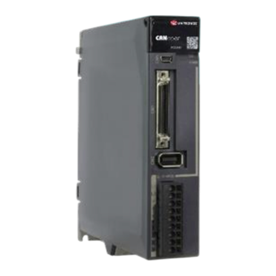
Page 15: Part Names
UMD-E5-S 1.4 Part Names 200VAC,rated power from 50W to 400W Separate STO safety connection terminals are available only for -FS02 drives Name Description A module for Servo status displays and parameter Panel Operator settings Connects a computer “FW upgrade” USB Connector EtherCAT Input Connector Connect to an EtherCAT device IO Signal Connector... - Page 16 UMD-E5-S Name Description ⚫ RUN: running indicator lamp EtherCAT communication ⚫ ERR: Error indicator lamp indicators ⚫ POWER: power on indicator lamp EtherCAT Output Connector Connects to an EtherCAT device or be vacant Lit while the main circuit power is being supplied Note: CHARGE Indicator Lamp Even if you turn OFF the main circuit power supply, this indicator will...
- Page 17 UMD-E5-S Name Description Panel Operator A module for Servo status displays and parameter settings Connects a computer for “FW upgrade” USB Connector EtherCAT Input Connector Connect to an EtherCAT device ⚫ L1、L2、L3: main power input terminals Main Circuit Connector ⊕1, ⊕2, ㊀: DC terminals ⚫...
- Page 18 UMD-E5-S 400VAC, rated power from 1kW to 3kW The figure above shows an example of a product with a rated power of 1kW to 1.5kW. Products with a rated power of 2kW~3kW are similar in appearance and have the same components. Name Description Panel Operator...
- Page 19 UMD-E5-S Name Description Lights up when the main circuit is powered on. Note: CHARGE Indicator Lamp If voltage remains in the capacitors inside the drive after the main circuit has been switched off, and the indicator lamp will be ON, do not touch the main circuit and motor terminals at this time to avoid electric shock.
-
Page 20: Ratings And Specifications
UMD-E5-S Name Description ⚫ L1, L2, L3: main power input terminals Main Circuit Port ⊕, ㊀: DC Connectors ⚫ ⚫ L1C, L2C: control power input terminals Control Circuit Port ⚫ B1, B2, B3: external regenerative resistor Connectors Motor Power Connection Socket for motor power cable. - Page 21 UMD-E5-S Drive Model: UMD- 0010E 0015E 0020E 0030E 0050E 0075E Continuous Output Current [Arms] 12.0 17.0 27.3 Max Output Current [Arms] 10.9 17.7 24.7 37.8 53.0 70.7 Mains Power Equipment Capacity [kVA] (3- 12.0 phase) General specifications Description Single-phase AC 200V~240V, -15%~+10%, 50Hz/60Hz 200VAC 3-phase AC200V~240V, -15%~+10%, 50Hz/60Hz (rated power ≥...
- Page 22 UMD-E5-S General specifications Description P-OT (Forward Drive Prohibit), PCL (Forward External Torque Limit) or EXT1 (Touch Probe 1), NCL (Reverse External Torque Limit) or EXT2 (Touch Probe 2). Allowable voltage range: 5 VDC to 30 VDC Number of output points: 3 (1 of them fixed for Servo Alarm) Output Signals are TGON (Rotation Detection), ALM (Servo Alarm), Output Signals COIN (Positioning Completion).
-
Page 23: Dimensions
UMD-E5-S General specifications Description Communications Communications Conforms to USB2.0 standard (12 Mbps), OTG Standard Display Five 7-segment LEDs Indicator Lamps CHARGE, POWER, SYS, RUN, ERR, L/A IN , L/A OUT Panel Operator 4 Buttons ⚫ Rated power from 50W to 400W must connect an external regenerative resistor. - Page 24 UMD-E5-S 200VAC, rated power from 1.5kW to 2kW 400VAC, rated power from 1kW to 1.5kW...
- Page 25 UMD-E5-S 400VAC, rated power from 2kW to 3kW 400VAC, rated power from 5kW to 7.5kW...
- Page 26 UMD-E5-S...
-
Page 27: System Configuration
UMD-E5-S 1.7 System Configuration 1.7.1 Example Diagram 200VAC, rated power from 50W to 400W Power Supply Single-phase, 200 VAC to 240 VAC Circuit Breaker USB Cable Noise Filter EtherCAT Cables I/O Signals Cable Magnetic Contactor External Regenerative Resistor Motor Power Grounding Supply Cable Encoder Cable... - Page 28 UMD-E5-S 200VAC, rated power from 750W to 2kW Power Supply Three-phase, 200 VAC to 240 VAC Circuit Breaker Noise Filter USB Cable Magnetic Contactor EtherCAT Cables I/O Signals Cable External Regenerative Resistor Motor Power Grounding Supply Cable Encoder Cable...
- Page 29 UMD-E5-S 400VAC, rated power from 1kW to 7.5kW Take a 1kW drive as an example: Three-phase power supply AC200V~AC240V Circuit Breaker Protect the power line and cut off the current in the event of an overcurrent. Filter Prevent external noise from the power cable.
-
Page 30: Minimum System Configuration
Protection against external noise interference from the power cable, with the Noise filter current rated at 10A or 20A. Electromagnetic ON/OFF control of the input circuit. contactor External The minimum resistance value of the external regenerative resistor varies with regenerative the drive model. resistor Drive UMD-E5-S Series Servo Drives. -
Page 31: Peripheral Devices Specification
UMD-E5-S Component Specification Motor Suitable for use with B5 and B6 motors Controller The device provided for servo applications, mechanical motion programming. Encoder cables, motor power cables, EtherCAT communication cables, IO Cables cables, etc. 1.7.3 Peripheral Devices Specification Min. value of Spec. -
Page 32: Part Numbers
UMD-E5-S 1.8 Part Numbers Drive model Power Motor model Encoder cable Power cable UMM-0000BA-B5 UMD-0000B-E5-S UMM-0000BAB-B5 UMM-0001BA-B5 UMD-0001B- E5-S 100W UMM-0001BAB-B5 UMC-B5A-PN-(03/05/10) (No Brake) UMM-0002BA-B5 UMC-B5A-PB-(03/05/10) (With Brake) UMD-0002B- E5-S 200W UMM-0002BAB-B5 UMC-B5-FA-(03/05/10) UMM-0004BA-B5 UMD-0004B- E5-S 400W UMM-0004BAB-B5 UMM-0007CA-B5 UMD-0007CU- E5-S 750W UMM-0007CAB-B5 UMC-B5B-PN-(03/05/10) (No Brake) - Page 33 UMD-E5-S UMC-B6C-PN-(03/05/10) (No Brake) UMM-0055EAB-B6 UMC-B6C-PB-(03/05/10) (With Brake) UMM-0075EA-B6 UMC-B6D-PN-(03/05/10) (No Brake UMC-B6D-PB-(03/05/10) (With Brake) UMM-0075EAB-B6...
-
Page 34: Chapter 2 Installation
UMD-E5-S Chapter 2 Installation 2.1 Installation Precautions Installation Near Sources of Heat ⚫ Implement measures to prevent temperature increases caused by external heat sources so that the ambient temperature of the Drive is within the specified limits. Installation Near Sources of Vibration ⚫... -
Page 35: Mounting Hole Dimensions
UMD-E5-S 2.3 Mounting Hole Dimensions Use all mounting holes to securely mount the Drive to the mounting surface. To mount the Drive, use a screwdriver that is longer than the depth of the Drive. Wiring diagram for mounting holes at 200VAC Wiring diagram for mounting holes at 400VAC... -
Page 36: Mounting Interval
UMD-E5-S 2.4 Mounting Interval Installing One Drive in a Control Cabinet When installing a single Drive use Figure 2-2 as a reference for free space around the installation. Installing a single Drive in a control cabinet Figure 2-2 Installing multiple Drives in a Control Cabinet When installing a multiple Drives use Figure 2-3 as a reference for free space around the installation. -
Page 37: Chapter 3 Wiring And Connecting
UMD-E5-S Chapter 3 Wiring and Connecting 3.1 Precautions for Wiring 3.1.1 General Precautions Never change any wiring while power is being supplied, in case a risk of electric shock or injury. DANGER Wiring and inspections must be performed only by qualified engineers. ◼... -
Page 38: Countermeasures Against Noise
UMD-E5-S Use a molded-case circuit breaker or fuse to protect the main circuit. ◼ The Drive connects directly to a commercial power supply; it is not isolated through a transformer or other device. Always use a molded-case circuit breaker or fuse to protect the Servo System from accidents involving different power system voltages or other accidents. - Page 39 UMD-E5-S Wiring example for countermeasures against noise Figure 3-1 Drive Motor Noise Filter 200 VAC 2.0 mm min. 2.0 mm min. Operation relay sequence User signal generators Noise Filter Power supply 2.0 mm min. Ground plate External ground: Use a dedicated ground. ·...
- Page 40 UMD-E5-S Separate the Noise Filter ground wire from the output lines. Do not place the Noise Filter ground wire, ⚫ output lines, and other signal lines in the same duct or bundle them together. Noise Filter Noise Filter The ground wire can be close to the input lines.
-
Page 41: Grounding
UMD-E5-S 3.1.3 Grounding Implement grounding measures as described in this section. Implementing suitable grounding measures will also help prevent malfunctions, which can be caused by noise. Always use an unpainted backplane for electrical cabinets. Observe the following precautions when wiring the ground cable. Ground the Drive to a resistance of 100 mΩ... -
Page 42: Basic Wiring Diagrams
UMD-E5-S 3.2 Basic Wiring Diagrams 200V AC, Rated power from 50W to 400W QF[1] Drive SA[3] DICOM1 +24V 3.3 kΩ FLT[1] S-ON KM[1] P-OT External regenerative resistor (For alarm Ry[1] N-OT display) PL[1] Power Power DICOM2 EXT1 Main Circuit Terminals KM[1] EXT2 KM[1]... - Page 43 UMD-E5-S 200VAC, Rated power from 750W to 2kW Drive QF[1] Motor terminals SA[3] Main Circuit Terminals FLT[1] KM[2] PG5V PG0V KM[1] CLK+ Encoder CLK- terminals 编码器 (For alarm (CN2) Ry[1] display) BAT+ PL[1] BAT- Power Power KM[1] ㊀ SA[1] KM[1] KM[2] Ry[1] KM[1]...
-
Page 44: Terminals Arrangements
UMD-E5-S 400VAC, rated power from 1kW to 7.5kW Drive QF[1] Motor power cable terminals SA[3] Main circuit terminals FLT[1] KM[2] PG5V PG0V KM[1] CLK+ CLK- Encoder connector Encoder (CN2) (For servo alarm Ry[1] display) BAT+ PL[1] BAT- Servo Servo KM[1] Power ON Power OFF ㊀... - Page 45 UMD-E5-S 200VAC, rated power from 750W to 2kW...
- Page 46 UMD-E5-S 400VAC, rated power from 1kW to 1.5kW...
- Page 47 UMD-E5-S...
- Page 48 UMD-E5-S 400VAC, rated power from 2kW to 3kW...
- Page 49 UMD-E5-S 400VAC, rated power from 5kW to 7.5kW...
-
Page 50: Wiring The Power Supply To Drive
UMD-E5-S 3.4 Wiring the Power Supply to Drive 3.4.1 Terminals Arrangement 200VAC, rated power from 50W to 400W Symbols Name Specifications and Reference Main circuit power Single-phase, 200 VAC to 240 VAC, -15% to +10%, L1, L2 supply input terminals 50Hz or 60Hz Regenerative Resistor Connects a regenerative resistor with a minimum... - Page 51 UMD-E5-S Symbols Name Specifications and Reference Main circuit power Three-phase, 200 VAC to 240 VAC, -15% to +10%, L1, L2, L3 supply input terminals 50Hz or 60Hz For using a DC reactor, remove the short wiring, and ⊕1, ⊕2 DC reactor terminals connect a DC reactor between ⊕1 and ⊕2.
- Page 52 UMD-E5-S Symbol Name Specifications When using the built-in regenerative resistor: Regenerative resistor Keep the connection between B2 and B3 shorted. connectors When using an external regenerative resistor: B1, B2, B3 Please remove the jumper between B2 and B3 and connect the external regenerative resistor between B1 and B2.
- Page 53 UMD-E5-S Symbol Name Specifications Grounding terminals Connect the power supply earth terminal for earthing.
-
Page 54: Wiring A Regenerative Resistor
UMD-E5-S 3.4.2 Wiring a Regenerative Resistor When the busbar capacitance is insufficient, the driver needs an external regenerative resistor. The minimum resistance of a regenerative resistor varies by driver model, and the detailed specifications are shown in the table below. Connection Diver model Rated power... - Page 55 UMD-E5-S Connect the external regenerative resistor as following to avoid damaging the drive or malfunction. It is necessary to connect an external regenerative resistor for the drives rated ◼ power from 50W to 400W. The minimum resistance value of the external regenerative resistor is 45 ohms.
-
Page 56: Wiring Procedure
UMD-E5-S 3.4.3 Wiring Procedure Prepare the following items before preparing the wiring for the Main Circuit Terminals and Control Circuit Terminals. Required Item Description ⚫ Flat-blade screwdriver: commercially available screwdriver with Flat-blade screwdriver or tip width of 3.0 mm to 3.5 mm Terminal removal tool ⚫... - Page 57 UMD-E5-S Step 4 Crimp the cable that has been inserted into the ferrule, and cut off the cable conductor portion protruding from the ferrule (The allowable protruding length after cutting should not be more than 0.5 mm). Cut off th e protruding porti on Step 5 Use the flat-blade screwdriver or the terminal removal tool to press down the spring button corresponding...
-
Page 58: Motor Connection Diagram
UMD-E5-S 3.4.4 Motor Connection Diagram... -
Page 59: Power Input Wiring Specifications
UMD-E5-S 3.4.5 Power Input Wiring Specifications Power Input Wiring Example 200VAC, rated power from 50W to 400W Use single-phase 200 VAC to 240 VAC as the power input for the Drives rated power from 50W to 400W. QF[1] SA[3] Drive FLT[1] Motor KM[2]... - Page 60 UMD-E5-S The following figure shows the wiring example for using the three-phase AC input power. Drive QF[1] SA[3] FLT[1] KM[2] Motor KM[1] Power Power KM[1] SA[1] KM[1] ㊀ KM[2] Ry[1] KM[1] SA[2] ALM- (For alarm Ry[1] ALM+ display) +24V PL[1] The following figure shows the wiring example for using the single-phase AC input power.
-
Page 61: Wiring The Encoder
UMD-E5-S 【When using a three-phase AC power supply】 QF[1]: Molded-case circuit breaker SA[1]: Surge Absorber 1 SA[2]: Surge Absorber 2 SA[3]: Surge Absorber 3 FLT[1]: Noise Filter Ry[1]: Relay PL[1]: Indicator lamp KM[1]: Magnetic Contactor (for control power supply) KM[2]: Magnetic Contactor (for main circuit power supply) 3.5 Wiring the Encoder 3.5.1 Connection Diagram... -
Page 62: Battery Case Connection
UMD-E5-S 3.5.2 Battery Case Connection Absolute encoders require a battery supply to retain the absolute encoder data when ◼ the Drive power is removed. Battery model: LS 14500 (3.6V, AA) ◼ CAUTION Replace the battery if the alarm A.47 or A.48 was occurred, and perform the ◼... -
Page 63: I/O Signal Connections
UMD-E5-S 3.6 I/O Signal Connections 3.6.1 Signal Diagram NOTE The signal definitions for the IO signals of all drives are the same. The signal name in the diagram above is predefined at the factory. You can can assign the following signals by Pn509, Pn510, and Pn511, see the section 6.7 IO Signal Allocation in detail. -
Page 64: Wiring Description
UMD-E5-S Name Type Function PBO_P Output Division Output of Encoder, channel B. PBO_N Output PAO_P Output Division Output of Encoder, channel A. PAO_N Output PCO_P Output Division Output of Encoder, channel C. PCO_N Output 3.6.3 Wiring Description Input Signals Wiring The input signals of the Drive are divided into two groups, and the details are as following. - Page 65 UMD-E5-S Output Signals Wiring Taking the output signal TGON as an example, Figure 3-4 shows the connection diagram for using the optocoupler or relay, and the wiring of other output signals wiring is the same as it. TGON wiring diagram Figure 3-4 24 VDC 24 VDC...
-
Page 66: Holding Brake Wiring
UMD-E5-S 3.6.4 Holding Brake Wiring A holding brake is used to hold the position of the moving part of the machine when the Drive is turned OFF so that moving part does not move due to gravity or an external force. You can use the brake that is built into a Motor with a Brake, or you can provide one on the machine. -
Page 67: Communication Connections
UMD-E5-S Drive 3.3 kΩ +24V IN 1 kΩ EXT1 1 kΩ EXT2 The timing sequence between input signals and trigger is as shown below. EXT1 EXT2 Touch Probe Rising edge Falling edge trigger 3.7 Communication Connections... -
Page 68: Usb Communication Cable
Connection Diagram Cable Description You can purchase the USB Communication Cable provided by UNITRONICS “USB2-CAB200”, or you can purchase the commercially available products yourself The plug connected to your PC is USB The plug connected to your PC is USB Type-A, and the plug connected to the Drive is Mini USB Type-B... -
Page 69: Chapter 4 Basic Settings
UMD-E5-S Chapter 4 Basic Settings You can implement the functions of parameter setting, display, monitoring, alarm, adjustment, etc. of the Drive in the following two ways. Use the Panel Operator of the Drive ⚫ Send SDO command. ⚫ 4.1 Panel Operator 4.1.1 Key Names and Functions There is a Panel Operator on the front of the Drive, as is shown in Figure 4-1. -
Page 70: Basic Mode Selection
UMD-E5-S 4.1.2 Basic Mode Selection The basic modes include: Status Display Mode, Parameter Setting Mode, Utility Function Mode, and Monitor Mode. Select a basic mode with [M] key to display the operation status, set parameters and operation references, as is shown in Figure 4-2. Select a basic mode Figure 4-2 Status Display... -
Page 71: Status Display Mode
UMD-E5-S 4.1.3 Status Display Mode Power ON the Drive and wait for a while, the Panel Operator will initially display the Servo Status. The information displayed by the status is divided into two parts: The first two digits are called Bit Data, what indicates the signal states during the operation of Drive. ⚫... - Page 72 UMD-E5-S The display meanings of Code are shown in Table 4-2. Table 4-2 Display meanings of Code Code Meaning Servo initialization failed (check the encoder connection) Servo OFF (Motor Power OFF) Servo Ready Servo ON (Motor Power ON) Quick Stop State Servo Alarm State Safe State Forward Drive Prohibited...
-
Page 73: Parameter Setting Mode
UMD-E5-S 4.1.4 Parameter Setting Mode Functions can be selected or adjusted by setting parameters. There are two types of parameters. Function Parameters: the functions allocated to each digit of the Panel Operator can be selected. ⚫ Adjustment Parameters: a parameter is set to a value within the specified range of the parameter. ⚫... - Page 74 UMD-E5-S Step 9 Press [▲] key once, changing the value of the 2nd digit from 0 to 1. Step 10 Press and hold [◄] key for 1 second or more to return to the display of the Pn003 parameter value, or press the [M] key to return to the display of the Pn003.
- Page 75 UMD-E5-S The example below shows how to change parameter Pn504 (Deviation Counter Overflow Alarm) from 41943040 to 42943240. Step 1 Press [M] key several times to select the Parameter Setting Mode. Step 2 Press [▲] key or [▼] key to select the parameter Pn504. Step 3 Press [◄] key to display bottom four digits of the current value of Pn504.
-
Page 76: Monitor Mode
UMD-E5-S 4.1.5 Monitor Mode The Monitor Mode can be used for monitoring the reference values, I/O signal status, and Drive internal status. The Monitor Mode can be selected during Motor operation. Select Monitor Mode The example below shows how to display, the contents of monitor number Un003 (when the Motor rotates at 100). - Page 77 UMD-E5-S Monitor Number Content of Display Unit ℃ Un022 Main board temperature The status (low level or high level) of input signal allocated to each input terminal is displayed. Display Monitor No. Description 0: CN1-14 (lit for low level, not lit for high level) 1: CN1-15 (lit for low level, not lit for high level) Un005 2: CN1-16 (lit for low level, not lit for high level)
-
Page 78: Utility Function Mode
UMD-E5-S 4.1.6 Utility Function Mode This section describes how to apply the basic operations using the Panel Operator to run and adjust the Motor. The following table shows the parameters in the Utility Function Mode. Function Number Name Fn000 Alarm trace data display Fn001 Initialize parameter settings Fn002... - Page 79 UMD-E5-S Step 4 Press [▲] key or [▼] key to view the other alarm data. [▲] [▼] Step 5 Press the [◄] key to return to the display of the Fn000. Press and hold [◄] key for 1 second or more to clear all the alarm trace data. ----End Fn001 (Initialize parameter settings) The following are the steps to initialize parameter settings.
- Page 80 UMD-E5-S Fn005 (Automatic offset-adjustment of Motor current detection signal) Motor current detection offset adjustment has performed at UNITRONICS before shipping. Basically, the user need not perform this adjustment. Execute the automatic offset adjustment if the torque ripple is too big when ◼...
- Page 81 UMD-E5-S Fn006 (Manual offset-adjustment of Motor current detection signal) To adjust the offset, perform the automatic adjustment (Fn005) first. And if the torque ripple is still big after the automatic adjustment, perform the manual offset-adjustment as follow. Please carefully execute the manual offset-adjustment, in case worsen the ◼...
- Page 82 UMD-E5-S Fn007 (Software version display) The following are the steps to display the software versions. Step 1 Press [M] key several times to select the Utility Function Mode. Step 2 Press [▲] key or [▼] key to select the function number Fn007. Step 3 Press [◄] key to display the software versions.
- Page 83 UMD-E5-S Step 3 Press [◄] key, and Panel Operator displays as below. Step 4 Press [M] key to reset the absolute encoder multi-turn data. Step 5 Press [◄] key to return to the display of the Fn010. ----End Fn011 (Absolute encoder alarm reset) The clearing of multiturn data from the absolute encoder needs to be performed in the ◼...
-
Page 84: Chapter 5 Sto
UMD-E5-S Chapter 5 STO 5.1 Introduction The UMD-E5-S Servodrive has the integrated safety function “Safe Torque Off” (STO) according to IEC 61800-5-2, which is equivalent to an uncontrolled stop in accordance with stop category 0 of IEC 60204- 1, which can protect people from dangerous movements of the machine and reduce the risk of operator. The safe torque off (STO) function is a safety function that shuts the motor current and turns off motor output torque by turning off the driving signal of the servo driver’s internal power transistor, when safety input signal is detected. -
Page 85: Functions And Features
UMD-E5-S Reliability block diagram Figure 5-2 Input 1 Actuator 1 Power Common Supply Cause Input 2 Actuator 2 5.1.2 Functions and Features The functions or features of STO are as follows: The safe state is the hardware shutdown of all PWMs, which make the motor torque off. ⚫... -
Page 86: Alarms
UMD-E5-S Never touch the terminals while the power is on. ⚫ Since the STO function only cuts off the torque output of the motor and does not cut off the physical connection between the drive and the motor, there is a risk of electric shock. Use products that have been safety-confirmed or meet safety specifications for parts used on ⚫... -
Page 87: Applicable Standards
UMD-E5-S Item Specification Overvoltage Category Isolation Voltage Input to Output: 2.7 kV; Input to Earth: 2.0 kV Insulation Resistance 50 MΩ or more To avoid the risk of crosstalk to signal cables, please segregate the power interface cable from ⚫ signal cables or state alternative mitigation methods. - Page 88 UMD-E5-S 50W ~ 400W 750W~7.5kW Please use the PELV/SELV switching power supplying to the IO signal of the STO function. ⚫ The external signal shall meet the Idle-current principle. ⚫ WARNING Signal Name Function - (Do not use these pins because 24 V Power Supply they are connected to internal circuits) 24 V...
-
Page 89: Function Description
UMD-E5-S Item Characteristics Description - Maximum Allowable Voltage 35 V dc - Maximum Allowable Current 80 mA dc Voltage between EDM+ and EDM- when Maximum ON Voltage Drop 1.0 V current is 80 mA Time from a change in HWBB1 or HWBB2 Maximum Delay Time 5 ms until a change in EDM... -
Page 90: S-Rdy (Servo Ready Output) Signal
UMD-E5-S The relationship between the State and the signals of HWBB1 and HWBB2 is shown in Table 5-2. Table 5-2 The relationship between the State and the signals of HWBB1 and HWBB2 Item Logic HWBB1 HWBB2 - State Alarm Alarm Turn OFF input signals (HWBB1 and HWBB2) for taking effect the STO function, the power supplied to the Motor will be cut off within 5 milliseconds. -
Page 91: Bk (Brake Ouput) Signal
UMD-E5-S 5.4.4 /BK (Brake Ouput) Signal If the STO function takes effect when the HWBB1 or HWBB2 signal is OFF, the /BK (Brake) signal will turn OFF. At that time, the setting in Pn506 (Brake Reference-Servo OFF Delay Time) will be disabled. HWBB1 HWBB2 (Brake released) - Page 92 UMD-E5-S In this case, the STO function will be disabled and the Drive will not be able to implement the ⚫ safety function by the Safety Function Device. WARNING If the shorting pins are removed and the Safety Function Device is not connected, the Drive ⚫...
-
Page 93: Connecting A Safety Function Device
UMD-E5-S 5.5.1 Connecting a Safety Function Device Step 1 Remove the shorting pins on the Safety Connector as shown in Figure 5-3. Remove the shorting pins Figure 5-3 Step 2 Wiring the Safety Function Device Connect the Safety Function Device to the CN6port according to the wiring example shown in Figure 5-4. Wiring example for Safety Function Device Figure 5-4 Use armored cables to protect the HWBB1+ and HWBB2+ from short circuits. -
Page 94: Procedure
UMD-E5-S When the system is commissioned, or maintenance operations are performed, or a Drive is replaced re- validation tests must be run to check the operation of the STO function. It is recommended that the results of any conformation testing are kept as a record for future reference. •... -
Page 95: Chapter 6 Application Functions
UMD-E5-S Chapter 6 Application Functions 6.1 Power Supply The main circuit and control circuit of the Drive can be operated with AC power input. When AC power input is selected, single- phase or three phase power input can be used. You shall to set the parameter Pn007.1 and Pn007.3 (use AC power input) according to the applicable power supply. -
Page 96: Overtravel Limit
UMD-E5-S Parameter Setting Reference Diagram Torque reference Encoder pulse division output Forward Reference Phase B advanced Rotation speed 1: CW Torque reference Encoder pulse division output Phase A Reverse Reference advanced Rotation speed 6.3 Overtravel Limit 6.3.1 Function Description Overtravel is a safety function of the Drive that forces the Motor to stop in response to a signal input from a limit switch that is activated when a moving part of the machine exceeds the safe range of movement. -
Page 97: Enabling/Disabling The Overtravel Signal
UMD-E5-S Type Name Setting Meaning Forward run allowed. Normal operation status. P-OT CN1-15 Forward run prohibited. Forward overtravel. Input Reverse run allowed. Normal operation status. N-OT CN1-16 Reverse run prohibited. Reverse overtravel. 6.3.3 Enabling/Disabling the Overtravel Signal Parameters can be set to disable the overtravel signal. If the parameters are set, there is no need to wire the overtravel input signal. - Page 98 UMD-E5-S Force Stop feature selection of stop methods The stop method of the forced stop function is selected by Pn003.2 (the stop method at the time of forced stop). When to Number Name Range Unit Default Illustrate take effect [0] The motor is decelerated according to bus 402 protocol The stop 605A and 6084/6085 objects...
-
Page 99: Motor Stopping Methods
UMD-E5-S Enter the servo OFF command (Disable Operation command), enter the rdy state, please enter the servo ON command (Enable Operation command) again. Mandatory stop ESTP signal ON(Normally run) ON(Normally run) requirement Disable Enable Enable Controlword operation operation operation (6040h) Operation Switched Operation... -
Page 100: Motor Stop Methods For Gr.1 Alarms, Safety State And Servo Off
UMD-E5-S 6.5.1 Motor Stop Methods for Gr.1 Alarms, Safety State and Servo OFF You can select the Motor stopping methods for Gr.1 Alarms occur, in Safe state or Servo OFF by setting the parameter Pn003.0. Parameter Setting Stop Method After Stopping When Enabled Stopping by dynamic 0 [Default]... -
Page 101: Reverse Brake Torque Limit Setting
UMD-E5-S 6.5.4 Reverse Brake Torque Limit Setting If Pn004.0 is set to 3 or 4, the Motor will be decelerated to a stop using the torque set in Pn405 as the maximum torque. Parameter Name Range Unit Default When Enabled Pn405 Reverse Brake Torque Limit 0 to 350... -
Page 102: Brake Operating Sequence
UMD-E5-S 6.6.2 Brake Operating Sequence You must consider the time required to release the brake and the time required to brake to determine the brake operation timing, as described below. Servo ON command Servo OFF Servo ON Servo OFF Power not Power not Motor power status Power supplied... -
Page 103: Output Timing Of /Bk Signal When Motor Is Stopped
UMD-E5-S 6.6.4 Output Timing of /BK Signal when Motor is Stopped When the Motor is stopped, the /BK signal turns OFF as soon as the S-OFF (Servo OFF) command is received. Use the servo OFF delay time (Pn506) to change the timing to turn OFF power supply to the Motor after the S-OFF command is input. -
Page 104: Output Timing Of /Bk Signal When Motor Is Operating
UMD-E5-S 6.6.5 Output Timing of /BK Signal when Motor is operating If an alarm occurs or S-OFF command is received while the Motor is operating, the Motor will start stopping and the /BK signal will be turned OFF. You can adjust the timing of /BK signal output by setting the Brake Enable Waiting Time (Pn508). -
Page 105: Multiturn Limit Setting
UMD-E5-S For details about replacing the battery, see the section 3.5.2 Battery Case Connection. 6.7.3 Multiturn Limit Setting The multiturn limit is used in position control for a turntable or other rotating body. For example, consider a machine that moves the turntable shown in the following diagram in only one direction. -
Page 106: Encoder Pulse Dividing Output
UMD-E5-S NOTE The multiturn data will always be 0 in the following cases. It is not necessary to reset the absolute encoder in these cases. When you use a single-turn absolute encoder ⚫ When you set Pn002.2 = 1 (Use the encoder as an incremental encoder) ⚫... -
Page 107: I/O Signal Allocations
UMD-E5-S Name Range Unit Default When Enabled Pn200 PG dividing ratio 16 to 16384 1 pulse 16384 After restart Set the number of pulses for PG output signals (PAO,/PAO,PBO,/PBO) externally from the servo ⚫ drive through Pn200. ⚫ Feedback pulses from the encoder per revolution are divided inside the servo drive by the number set in Pn200 before being output. -
Page 108: Default Input Signals
UMD-E5-S If you allocate two or more signals to the same input circuit, a logical OR of the ◼ inputs will be used and all of the allocated signals will operate accordingly. This may result in unexpected operation. Since the pins have priority, only the highest priority pin is in effect if a signal is ◼... -
Page 109: Output Signal Allocations
UMD-E5-S Input Signal Name Assigned Value EXT2 Probe TouchProbe Input 2 E-STOP Forced Stop Input 6.8.2 Output Signal Allocations Allocation Description The I/O signal connector (CN1) on the Drive provides three group of pins (points) for allocating the output signals, corresponding to the parameter Pn511, as is shown in Figure 6-3. Output signals allocated Figure 6-3 Reserved settings... -
Page 110: Torque Limit
UMD-E5-S Signal Name Value Position Comparison Assignment example An example of replacing a Servo Ready Output (S-RDY) signal assigned to CN1-12, 13 with a Speed Detection Output (TGON) signal assigned to CN1-10, 11 is shown below. Pn511 = H - 2 1 - Before replacement After... - Page 111 UMD-E5-S Without Internal With Internal Torque Limits Torque Limits Maximum Torque Torque Limit Speed Speed Pn401 Pn402...
-
Page 112: External Torque Limits
UMD-E5-S 6.9.2 External Torque Limits You can limit the torque only when required by the operating conditions of the machine by turning a signal ON and OFF. You can use this for applications such as stopping on physical contact, or holding a workpiece with a robot. -
Page 113: Semi F47 Function
UMD-E5-S Changes in the Output Torque for External Torque Limits The following table shows the changes in the output torque when the internal torque limit is set to 300%. In this example, the Motor direction is set to Pn001.0=0 (Use CCW as the forward direction). /NCL /PCL H Level... - Page 114 UMD-E5-S (Pn407), which is a relative percentage of Pn401 (Forward Internal Torque Limit) or Pn402 (Reverse Internal Torque Limit). The Drive controls the torque limit for the set time (Pn407) after the Undervoltage warning is cleared. Main circuit power interruption time Main circuit input power supply The output torque is limited to suppress...
-
Page 115: Chapter 7 Ethercat Communications
UMD-E5-S Chapter 7 EtherCAT Communications 7.1 Introduction EtherCAT is a real-time Industrial Ethernet technology originally developed by Beckhoff Automation. The EtherCAT protocol which is disclosed in the IEC standard IEC61158 is suitable for hard and soft real-time requirements in automation technology, in test and measurement and many other applications. The EtherCAT master sends a telegram that passes through each node. -
Page 116: Run Indicator
UMD-E5-S In addition, CN3-IN and CN4-OUT connectors have LINK and ACT indicators. CN3-IN CN4-OUT ACT indicator lamp LINK indicator lamp RUN: Running indicator lamp ERR: Error indicator lamp RUN Indicator The RUN indicator shows the status of EtherCAT communications. Indicator Description Status Pattern... -
Page 117: Ethercat Slave Information
The drive publishes network accessible properties via an EtherCAT Slave Information (ESI) file. This is an XML based file which is used by the network master. The ESI file for the UMD-E5-S Drives can be delivered to you from Unitronics by request Unilogic Software automatically support UMD drive series (no need for ESI) -
Page 118: Ethercat State Machine
UMD-E5-S 7.5 EtherCAT State Machine A state machine is used to manage the communications states between the master and slave applications, shown in following figure. Normally, the state of the slave responds based on requests from the master. Power ON Init (IP) (PI) -
Page 119: Communications Between Master And Slave
UMD-E5-S 7.6 Communications between Master and Slave PDO is used to transfer cyclic data. This is data that is transferred between the master and slave every network cycle. Typically, this is data required for operation of the drive; Control Word, Status Word, Set Point, etc…... -
Page 120: Chapter 8 Cia402 Drive Profile
UMD-E5-S Chapter 8 CiA402 Drive Profile... -
Page 121: Device Control
UMD-E5-S 8.1 Device Control 8.1.1 CiA402 State Machine The Drive runs in the specified status only when it is instructed according to the flowchart defined in CiA402. Start Stop at Fault Initialization Fault No Fault Ready Wait to Switch ON Quick Stop Running The states are described in the following table. - Page 122 UMD-E5-S State Description The stop process is completed, and all the drive functions are inhibited. Fault Parameter setting is allowed for users to eliminate faults. The control commands and state switchover are described as follows: CiA402 State Switchover Controlword (6040h) Statusword (6041h) Natural transition, and no control Start →...
-
Page 123: Stop Modes
UMD-E5-S 8.1.2 Stop Modes The Drive supports 5 stop modes described as below sections. Quick Stop Option Code (605Ah) This object determines what operation will be performed if a Quick Stop is executed. Data Index Subindex Name Access PDO Mapping Value Type Quick Stop... - Page 124 UMD-E5-S 605Ch: Disable Operation Option Code This object defines the operation that is performed if there is a move from Operation Enable state to Switched ON state. Data Index Subindex Name Access PDO Mapping Value Type Shutdown Option 0, 1 605Ch INT16 Code...
-
Page 125: Homing
UMD-E5-S 8.2 Homing 8.2.1 Homing (HM) Mode This mode searches for the home and determines the position relationship between home and zero. Home: mechanical home reference point, that is, the encoder C-pulse. ⚫ Zero: absolute zero point in the machine. ⚫... - Page 126 UMD-E5-S Object Name Value Description Home failed Homing successful Homing attained This flag bit is available when the Drive is in homing mode in running state and the target reached signal is active. No home error Homing error Homing timeout or deviation excessive Homing not completed Homing completed Homeflag...
- Page 127 UMD-E5-S Recommended Configuration RPDO TPDO Remarks 6040h: Controlword 6041h: Statusword Mandatory - 6098h: Homing Method Optional - 6099-01h: Speed during search for switch Optional - 6099-02h: Speed during search for zero Optional - 609A: Home Acceleration Optional - 6064h: Position Actual Value Optional 6060h: Modes of operation 6061h: Modes of Operation display...
-
Page 128: Homing Methods
UMD-E5-S 8.2.2 Homing Methods 6098h=1 (Use C pulse and negative limit switch) Servo drive needs to move at first toward negative direction fast till reaching the negative limit switch and then decelerate till stop. And then, servo motor will be bounced back slowly and find the target homing position. - Page 129 UMD-E5-S 6098h=5 or 6 (Use C pulse and negative reference point limit switch) It is used that reference point limit switch is on negative direction and positive direction is zero. That is on the edge of movement negative direction. Servo drive’s initial moving direction is relied on the status of reference point limit switch.
- Page 130 UMD-E5-S 6098h=11 to 14 (Use C pulse, reference point limit switch and negative limit switch) It is used that reference point limit switch is in the middle. And homing is according to C pulse, reference point limit switch and negative limit switch. The final mechanical point is the position of C pulse.
- Page 131 UMD-E5-S 6098h=19 or 20 (Use reference point limit switch) It is similar to 6098h=3 or 4 (Use C pulse and positive reference point limit switch), except that the target zero position no longer uses C-pulses and depends on reference point limit switches. 6098h=21 or 22 (Use reference point limit switch) It is similar to 6098h=5 or 6 (Use C pulse and negative reference point limit switch), except that the target zero position no longer uses C-pulses and depends on reference point limit switches.
- Page 132 UMD-E5-S 6098h=23 to 26 It is similar to 6098h=7 to 10 (Use C pulse, reference point limit switch and positive limit switch), except that the target zero position no longer uses C-pulses and depends on reference point limit switches and positive reference point limit.
-
Page 133: Torque Limits
UMD-E5-S 8.3 Torque Limits The following figure shows the block diagram for the torque limits. The torque is limited by the objects 60E0h and 60E1h. Torque limits Torque Torque offset 60E0h 60E1h Positive Torque Negative Torque Limit Value Limit Value Position Velocity Torque... - Page 134 UMD-E5-S Signal Description Home switch 0: Switched off; 1: Switched on - 3 to 15 Reserved CN1-14 0: Switched off (Active); 1: Switched on (Inactive) CN1-15 0: Switched off (Active); 1: Switched on (Inactive) CN1-16 0: Switched off (Active); 1: Switched on (Inactive) CN1-17 0: Switched off (Active);...
-
Page 135: Touch Probe
UMD-E5-S Signal Description CN1-17 0: Switched off (Active), 1: Switched on (Inactive) CN1-18 0: Switched off (Active), 1: Switched on (Inactive) - 21 to 23 Reserved Remote0 0: Switched off (Active), 1: Switched on (Inactive) Remote1 0: Switched off (Active), 1: Switched on (Inactive) -... - Page 136 UMD-E5-S Single Trigger Mode (60B8h bit1=0, or bit9=0) ⚫ 60B8h bit0 (bit8) 60B8h bit4 (bit12) Latch start Latch start 60B9h bit0 (bit8) 60B9h bit1 (bit9) 60BAh Latched position 1 Latched position 3 (60BCh) Probe input Continuous Trigger Mode (60B8h bit1=1, or bit9=1) ⚫...
- Page 137 UMD-E5-S Value Definition Reserved Disables the sampling at the rising edge of touch probe 1 input Enables the sampling at the rising edge of touch probe 1 input Disables the sampling at the falling edge of touch probe 1 input Enables the sampling at the falling edge of touch probe 1 input 6, 7 Reserved...
- Page 138 UMD-E5-S Value Definition Record the number of the touch probe 1 executions in the Continuous Trigger 6, 7 0 to 3 Mode. Values are cycled between 0 and 3. Touch probe 2 is disabled. Touch probe 2 is enabled. No latched position of the rising edge is stored for touch probe 2. A latch position of the rising edge is stored for touch probe 2.
- Page 139 UMD-E5-S Data Index Subindex Name Access Unit Range Default Type - - - 60BD TouchProbeNeg2PosValue INT32 Pn509.3、Pn510.0 parameter Pn509.3 and Pn510.0 parameters are mainly used to distribute signals to PIN CN1-17 and PIN CN1-18 respectively, and the set values 8 and 9 correspond to EXT1 (Probe TouchProbe Input 1) and EXT2 (Probe TouchProbe Input 2), respectively.
-
Page 140: Soft Limit Function
UMD-E5-S 8.6 Soft Limit Function This object defines the absolute positions of the limits to the target position (position demand value). Every target position is checked against these limits. The limit positions are specified in user-defined position reference units, the same as for target positions, and are always relative to the machine home position. -
Page 141: Chapter 9 Trial Operation
UMD-E5-S Chapter 9 Trial Operation 9.1 Preparations for Trail Operation The procedure for trial operation is given below. Step Meaning Reference Installation Install the Motor and Drive according to the installation conditions. First, Chapter 2 operation is checked with no load. Do not connect the Motor to the machine. Wiring and Connections Wire and connect the Drive. -
Page 142: Motor Operation Without A Load
UMD-E5-S 9.3 Motor Operation without a Load You use jogging for trial operation of the Motor without a load. Jogging is used to check the operation of the Motor without connecting the Drive to the host controller. The Motor is moved at the preset jogging speed. During jogging, the overtravel function is disabled. -
Page 143: Motor Operation With A Load
UMD-E5-S Forward rotation Reverse rotation Default forward rotation is Default forward rotation is counterclockwise (CCW) as viewed clockwise (CW) as viewed from from the load end of the Motor. the load end of the Motor. NOTE: The rotation direction of the Motor depends on the setting of Pn001.0 (CCW, CW). The figure above shows the default setting. -
Page 144: Preparations
UMD-E5-S 9.4.2 Preparations Always confirm the following before you perform the trial operation procedure for both the machine and Motor. Make sure that the Drive is connected correctly to both the host controller and the peripheral devices. ⚫ Overtravel wiring ⚫... -
Page 145: Program Jogging
UMD-E5-S 9.5 Program Jogging You can use program jogging to perform continuous operation with a preset operation pattern, travel distance, movement speed, acceleration/deceleration time, waiting time, and number of movements. You can use this operation when you set up the system in the same way as for normal jogging to move the Motor without connecting it to the host controller in order to check Motor operation and execute simple positioning operations. -
Page 146: Relevant Parameters
UMD-E5-S Operation in the program jogging Figure 9-2 Round trip in Round trip in positive direction negative direction Speed Speed Movement in Movement in Positive direction negative direction Speed Speed You shall set the Rotations (Pn164 and Pn168) and Max Speed (Pn165 and Pn169) to a proper value. If the Rotations is set too small or the Max Speed is set too large, it is possible that the maximum speed set cannot be reached. -
Page 147: Applicable Tools
UMD-E5-S 9.5.4 Applicable Tools Use the Panel Operator of the Drive ⚫ 9.5.5 Operation Procedure Use the Panel Operator of the Drive Before performing the Program Jogging (PJOG) operation by using the Panel Operator, you shall check and set the following parameters properly. Check and set the parameters Pn164 to Pn171 as proper values in advance, and ensure the movable parts have sufficient travel in the forward and reverse directions. -
Page 148: Chapter 10 Tuning
Chapter 10 Tuning 10.1 Overview 10.1.1 Basic Conception Tuning is the process of satisfying the servo performance by adjusting the parameters involved in the control law. Tuning Flow The process of tuning is usually an iterative process, and Figure 10-1 shows the general flow. General flow Figure 10-1 Start... -
Page 149: Before Tuning
Table 10-1 Comparison of the graphics before and after tuning Indicator Before tuning After tuning Speed step response Position following Anti-load disturbance 10.1.2 Control Block Diagram It is necessary to learn the Servo control principle and Figure 10-2 shows the Servo control block diagram. -
Page 150: Tuning Process
10.1.3 Tuning Process The Drive provides a variety of tuning methods, you can adjust the device according to the process shown in Figure 10-3, in order to obtain the desired Servo performance. Tuning Process Figure 10-3 Start Perform the Tuning-Less function Response acceptable Perform Load Inertia Identification function Perform the One-Parameter Auto-Tuning function... -
Page 151: Precautions Before Tuning
10.1.4 Precautions Before Tuning Before performing the tuning operation, make sure the limit function is available. ◼ Before performing the tuning operation, make sure that an emergency stop can be ◼ performed at any time. Before performing the tuning operation, you shall set the torque limit according to ◼... -
Page 152: One-Parameter Auto-Tuning
Applicated Case Applied for that no more than 30 times the load moment of inertia. ⚫ Applied for any rotation speed. ⚫ Relevant Parameters When Parameter Setting Meaning Classification Enabled Set the Tuning Mode as Tuning- Pn100.0 After restart Function [Default] less. - Page 153 Parameter Name Description Properly setting the Load Inertia Percentage is a prerequisite for the One-Parameter Auto-Tuning to obtain a better Servo performance. Load Inertia Pn106 Percentage You can calculate the load inertia percentage (difficult and complex) by yourself, or you can get it by the utility function Fn009 “Load Inertia Identification”...
-
Page 154: Application Restrictions
Applicated Case Applied for that more than 50 times the load moment of inertia. ⚫ Applied for any rotation speed. ⚫ Relevant Parameters Parameter Setting Meaning When Enabled Classification Set the Tuning Mode as One- Pn100.0 Parameter Auto-Tuning. Set the damping method in One- After restart Function Parameter Auto-Tuning as Standard. -
Page 155: Adjustment Method
stability, the bandwidth setting should be the largest in the torque loop, the speed loop is the second, and the position loop is the smallest. The following parameters need to be adjusted in each loop when performing Manual Tuning. Torque loop (Torque Control Mode) ⚫... - Page 156 Response Curve Description Adjustment method Properly increase the Speed Speed loop bandwidth is low Loop Gain or decrease the Speed Loop Integral Time. It is recommended to increase the Speed Loop Gain and decrease the Speed Loop Integral Time to obtain a larger speed loop bandwidth.
-
Page 157: Tuning Tools
10.3 Tuning Tools There is an Auto-Tuning Tool and a Manual Tuning Tool in Tuning tools. When using a tuning tool, the Drive will execute the position references generated internally, Figure 10-7 shows the block diagram in using a tuning tool. Block diagram in using a tuning tool Figure 10-7 Settings... -
Page 158: Auto-Tuning Tool
10.3.2 Auto-Tuning Tool Function Description With the Auto-Tuning Tool, the reference generator can plan the position curve and generate a position reference as inputs to the position loop. There are two operation patterns (POS0 and POS1), you can set their relevant parameters respectively. Figure 10-8 shows an example of position-speed timing diagram in PJOG operation. - Page 159 Auto-Tuning Tool flowchart Figure 10-10 Start Load Inertia Percentage Set parameters for reference generator Check and confirm the safety of the motion Use the Auto-Tuning Tool Result of execution Success Faulure Save Execute again Write parameters The following parameters are automatically adjusted when using the auto-tuning tool. Parameter Adjustment method Write into...
- Page 160 Relevant Parameters Parameter Setting Description When Enabled Classification - Pn106 Load Inertia Percentage Immediately Adjustment - Pn164 Turns for PJOG0 Immediately Adjustment - Pn165 Max Speed for PJOG0 Immediately Adjustment - Pn167 Stop Time for PJOG0 Immediately Adjustment - Pn168 Turns for PJOG1 Immediately Adjustment...
- Page 161 Step 4 Press [M] key to execute this operation, and Panel Operator display as below. Lit for that the last 3 digits are position loop gain. Lit for that the automatic The last 3 digits are vibration suppression is enabled the gain value.
-
Page 162: Feedback Speed Selection
10.4 Feedback Speed Selection The speed feedback from the encoder is the calculate result that the Drive read the position value from the encoder and differentiate time. There is a speed observer inside the Drive for detecting the speed of the Motor in real time. The detected speed can be used for host controller monitoring or as a speed feedback for the speed loop. -
Page 163: Vibration Suppression
10.5 Vibration Suppression 10.5.1 Notch Filter The notch filter is used to eliminate vibration caused by mechanical resonance. There are three notch filters in the Drive, those who can used independently or in combination, Figure 10- 11 shows the block diagram of using the notch filters. Block diagram of using the notch filters Figure 10-11 Motor... -
Page 164: If (Intermediate Frequency) Vibration Suppression
Parameter Setting Meaning When Enabled Classification - Pn188 Depth of Notch Filter 3 Immediately Adjustment - Pn189 Width of Notch Filter 3 Immediately Adjustment Set the frequency of notch filter to 5000, indicating the notch filter is unavailable. ⚫ The setting range of the depth is from 0 to 23. ⚫... -
Page 165: Load Oscillation Suppression
Parameter Setting Meaning When Enabled Classification Frequency of Vibration Suppression - Pn173 Immediately Adjustment Filter Adjust Bandwidth of Vibration - Pn174 Immediately Adjustment Suppression Filter - Pn175 Vibration Suppression Immediately Adjustment Lowpass Filter Time for Vibration - Pn176 Immediately Adjustment Suppression Highpass Filter Time for Vibration -... -
Page 166: Automatic Vibration Suppression
Parameter Setting Meaning When Enabled Classification Use the model following control and Pn150.0 After restart Function load oscillation suppression. - Pn155 Load Oscillation Frequency Immediately Adjustment Filter Time for Load Oscillation - Pn156 Immediately Adjustment Suppression Limit for Load Oscillation -... -
Page 167: Diagnostic Tools
Applied in Tuning-less, One-Parameter Auto-Tuning, Manual Tuning, and Manual-Tuning Tool When the automatic vibration suppression function is applied in the Tuning-less, One-Parameter Auto- Tuning, Manual Tuning, and Manual-Tuning Tool, the following parameters can be set temporarily. Parameter Setting Meaning When Enabled Classification -... - Page 168 Use the Panel Operator of the Drive The following are the steps to execute the load inertia identification by using the Panel Operator. Step 1 Make sure the drive is in manual tuning mode Step 1 Press [M] key several times to select the Utility Function Mode. Step 2 Press [▲] key or [▼] key to select the function number Fn009.
-
Page 169: Chapter 11 Alarm Displays
Chapter 11 Alarm Displays 11.1 Alarm Classifications There are three classifications of alarms for the Drive: Gr.1, Gr.2, and Warning. They will affect the display and operation for the Servo System. Classification Stopping Method Panel Display The Panel Operator displays between Alarm No Stops the Motor according to the and Servo state FLT by turns. - Page 170 Possible causes Confirm the method Action Take anti-interference Malfunction due to Confirm the runtime environment. countermeasures and then power noise the drive back in. Power on the drive. When an alert Drive failure Replace the drive. still occurs, it may be a drive failure. A.03:Motor overspeed Possible causes Confirm the method...
- Page 171 Possible causes Confirm the method Action Lower the position command Position commands are Try lowering the position command speed or command acceleration, or too fast speed before running. adjust the electronic gear ratio. The position With the EtherCAT command, the Try slowing down the instruction instruction accelerates position command acceleration is...
- Page 172 A.12:Overcurrent Possible causes Confirm the method Action The main circuit cable is wired incorrectly, or Confirm that the wiring is correct. Modify the wiring. the contact is poor The main loop cable is Confirm whether a short circuit has There is a possibility that the cable shorted internally or a occurred between the UVW phases will be short-circuited.
- Page 173 A.13:Overvoltage Possible causes Confirm the method Action The supply voltage is Adjust the AC/DC supply voltage Measure the supply voltage. out of specification to the product specifications. Improve power conditions and The power supply is in power the drive again after setting an unstable state or has Measure the supply voltage.
- Page 174 Possible causes Confirm the method Action When an external braking resistor is not Confirm the connection of the short Properly wire the short wiring. used, the short wiring wires of B2 and B3. of B2 and B3 falls off External regenerative resistors are poorly Confirm the wiring of the external Properly wired external...
- Page 175 Possible causes Confirm the method Action The load in operation is confirmed The load is too heavy, by the cumulative load rate, and the or the regeneration Revisit load conditions and regenerative processing capacity is capacity is exceeded operating conditions. confirmed by the regenerative load during operation rate.
- Page 176 Possible causes Confirm the method Action The external Confirm that the regeneration resistance Change it to the correct resistance regeneration resistance value is correct. value and capacity. value is too large Confermtat Tregnatien Rescisteins Drive failure Replace the drive. Valleus Correcht. A.1F:Short-to-ground fault Possible causes Confirm the method...
- Page 177 A.42:The motor power does not match the drive power Possible causes Confirm the method Action The drive capacity The drive capacity must be the same Match the capacity of the drive to does not match the as the motor capacity. the motor.
- Page 178 A.47:The absolute encoder battery voltage is too low Possible causes Confirm the method Action The battery is poorly Confirm the connection of the connected and not Properly connect the battery. battery. connected Replace the battery and clear the The battery voltage is Measure the voltage of the battery.
- Page 179 Possible causes Confirm the method Action Power on the drive. When an alarm Encoder failure still occurs, it is possible that the Replace the motor. motor is malfunctioning. Power on the drive. When an alert Drive failure Replace the drive. still occurs, it may be a drive failure.
- Page 180 A.58:Information such as encoder zone phase is empty or incorrect Possible causes Confirm the method Action Power on the drive. When an alarm Replace the motor or absolute Encoder failure still occurs, it is possible that the encoder. motor or absolute encoder is faulty. A.59:Information such as the motor body in the second area of the encoder is empty or wrong Possible causes Confirm the method...
- Page 181 A.71:SM Event synchronization event premature Possible causes Confirm the method Action EtherCAT Check the EtherCAT wiring and - communication error implement noise countermeasures. due to noise. The controller does not Modify the controller's update process data Examine the process data specified configuration so that it can update during a fixed period by the controller.
- Page 182 A.75:There was an error setting for the synchronization period Possible causes Confirm the method Action Synchronization timing (Sync0) fluctuations in Reboot the drive to re-establish - EtherCAT EtherCAT communication. communication The setting of object 60C2 is not an integer Check the setpoint of object 60C2 Correctly set object 60C2.
- Page 183 A.83:The motor is operating abnormally Possible causes Confirm the method Action A short circuit or a Confirm whether a short circuit has short circuit to the occurred between the UVW phases It is possible that the motor is ground occurs inside of the motor terminals and between faulty.
- Page 184 A.1B:The DB braking circuit is damaged Possible causes Confirm the method Action The motor is driven by Do not drive the motor by external Confirm the health status。 an external force force. Try the following measures. The rotational or Reduce the command speed of the The DB usage frequency is running energy at the motor.
-
Page 185: Warnings
Cause Way of confirmation Solution ⚫ Replace the battery and clear the Battery voltage below alarm. See “3.5.3 Installing or Measure the battery voltage 3.0V Replacing the Battery”. Re-apply power to the drive. If the Drive failure alarm still occurs, the drive may be Replace the drive. -
Page 187: Chapter 12 Parameters
Chapter 12 Parameters 12.1 Interpreting the Parameter Lists ”When Enabled” indicates the parameter take effective when: [After restart] the power supply is turned OFF and ON again. Index of the [Immediately] it was set. object dictionary Here lists the value of the parameter and Parameter their description... -
Page 188: Parameters Detailed
12.2 Parameters Detailed When Index Name Range Unit Default Enabled - 3164 Basic Function Selections 0 0000 to 0111 0000 After restart Pn000.0: Servo ON Enabled. Disabled. When turn the S-RDY signal ON, the Motor is excitation automatically. Pn000 Pn000.1: Forward Drive Prohibit Input Enabled. - Page 189 When Index Name Range Unit Default Enabled Application Function - 3166 0000 to 0100 0000 After restart Selections 2 Pn002.0: Reserved setting (Do not change). Pn002 Pn002.1: Reserved setting (Do not change). Pn002.2: Usage of Absolute Encoder Use the encoder as an absolute encoder. Use the encoder as an incremental encoder.
- Page 190 When Index Name Range Unit Default Enabled Application Function - 3167 0000 to 1032 0000 After restart Selections 3 Pn003.0: Motor Stopping Methods for Gr.1 Alarms, Servo OFF, STO, and Servo OFF Applying the dynamic brake and then let the Motor coast. Applying the dynamic brake and then place the Motor in DB state.
- Page 191 When Index Name Range Unit Default Enabled Application Function - 3168 0000 to 0025 0000 After restart Selections 4 Pn004.0: Motor Stopping Methods for Gr.2 Alarms Applying the dynamic brake and then let the Motor coast. Applying the dynamic brake and then place the Motor in DB state. Coast the Motor to a stop.
- Page 192 When Index Name Range Unit Default Enabled Application Function - 3169 00d0 to 33d3 00d0 After restart Selections 5 Pn005.0: Internal Torque Feedforward Method Use the general internal torque feedforward. Reserved setting (Do not use.) Use the high-speed internal torque feedforward. Reserved setting (Do not use.) Pn005.1: Local Control Method Use the parameter reference as default.
- Page 193 When Index Name Range Unit Default Enabled Application Function - 316A 0000 to 0001 0001 After restart Selections 6 Pn006.0: Bus Selection Do not use the Bus. Select the control method by the setting of Pn005.1. Pn006 Use EtherCAT. Pn006.1: Reserved setting (Do not change). Pn006.2: Reserved setting (Do not change).
- Page 194 When Index Name Range Unit Default Enabled Initial Display Selection When - 316C 0 to 9999 0010 After restart Power On Pn008 Set the displayed Un Number when power on the device. For example, set this parameter to 0, the display is Un000 after powering on the device. Application Function -...
- Page 195 When Index Name Range Unit Default Enabled - 31C8 Tuning Function 0001 to 1105 0001 After restart Pn100.0: Tuning Mode Tuning-less Reserved setting (Do not change). One-parameter auto-tuning Reserved setting (Do not change). Manual tuning Pn100 Pn100.1: Reserved setting (Do not change). Pn100.2: Automatic Vibration Suppression Selection Disabled.
- Page 196 When Index Name Range Unit Default Enabled 31CD Torque Reference Filter Time 0 to 2500 0.01ms Immediately Pn105 This parameter determines the bandwidth of torque reference filter, the filter is used to filter out the noise in torque reference. 31CE Load Inertia Percentage 0 to 9999 Immediately...
- Page 197 When Index Name Range Unit Default Enabled - 31D8 P/PI Switch Mode 0 to 4 After restart [0] Use torque reference as the condition (threshold setting: Pn117). Pn116 [1] Use position deviation counter as the condition (threshold setting: Pn118). [2] Use acceleration reference as the condition (threshold setting: Pn119). [3] Use the speed reference as the condition (threshold setting: Pn120).
- Page 198 When Index Name Range Unit Default Enabled - 31DF Threshold for Gain Switch 0 to 20000 Immediately Pn123 The threshold of speed reference for gain switching. Speed Threshold for Gain 31E0 0 to 2000 Immediately Switch Pn124 This parameter is available only when using position reference and actual speed as the condition (Pn121=8).
- Page 199 When Index Name Range Unit Default Enabled Model Following Control - 31FA 0000 to 0002 0000 After restart Function Pn150.0: Model Following Control Selection Do not use. Pn150 Use the model following control. Use the model following control and load oscillation suppression. Pn150.1: Reserved setting (Do not change).
- Page 200 When Index Name Range Unit Default Enabled Filter Time for Load 3200 2 to 500 0.1 ms Immediately Oscillation Suppression Pn156 If you increase this setting, the response characteristic can be softer but the effect of vibration suppression will be worse. Limit for Load Oscillation 3201 0 to 1000...
- Page 201 When Index Name Range Unit Default Enabled 320E Acc./Dec. Time for PJOG1 50 to 2000 Immediately Pn170 - 320F Stop Time for PJOG1 100 to 10000 1000 Immediately Pn171 - - 3210 Turns for Inertia Identification 0 to 1 Immediately To set the turns towards the forward direction in Inertia Identification operation.
- Page 202 When Index Name Range Unit Default Enabled Frequency Threshold for 3218 0 to 100 Immediately Vibration Detection Pn180 This parameter is used for automatic vibration suppression. 3219 Frequency of Notch Filter 1 50 to 5000 5000 Immediately Pn181 - - 321A Depth of Notch Filter 1 0 to 23...
- Page 203 When Index Name Range Unit Default Enabled 3294 Inner Speed Reference -6000 to 6000 Immediately Pn304 To set the inner Motor speed reference. This setting is available when servo is in inner speed control mode (Pn006.0 = 0 and Pn005.1 = 1). 3295 Jogging Speed 0 to 6000...
- Page 204 When Index Name Range Unit Default Enabled 32F6 Reverse Internal Torque Limit 0 to 350 Immediately Pn402 - Forward External Torque 32F7 0 to 350 Immediately Limit Pn403 - 32F8 Reverse External Torque Limit 0 to 350 Immediately Pn404 - 32F9 Reverse Brake Torque Limit 0 to 350...
- Page 205 When Index Name Range Unit Default Enabled Position Deviation Counter 335C 1 to 83886080 1 pulse 41943040 Immediately Overflow Threshold Pn504 It is considered the deviation counter has been overflowed and an alarm signal outputs when the deviation counter exceeds this setting. NOTE: the default setting depends on the encoder resolution.
- Page 206 When Index Name Range Unit Default Enabled Digital Input Signal - 3361 0000 to 7777 3210 After restart Allocations 1 Pn509.0: Allocate signal to CN1-14 S-ON P-OT N-OT P-CL N-CL G-SEL Pn509 HmRef Remote Pn509.1: Allocate signal to CN1-15 0 to 7: same as the allocation of CN1-14. Pn509.2: Allocate signal to CN1-16 0 to 7: same as the allocation of CN1-14.
- Page 207 When Index Name Range Unit Default Enabled Digital Input Signal - 3362 0000 to 0007 0004 After restart Allocations 2 Pn510.0: Allocate signal to CN1-18 S-ON P-OT N-OT P-CL N-CL Pn510 G-SEL HmRef Remote EXT1 EXT2 Pn510.1: Reserved setting (Do not change). Pn510.2: Reserved setting (Do not change).
- Page 208 When Index Name Range Unit Default Enabled Digital Output Signal - 3363 0000 to 0bbb 0210 After restart Allocations Pn511.0: Allocate signal to CN1-6, 7 COIN/VCMP TGON S-RDY Pn511 Remote0 Remote1 Pn511.1: Allocate signal to CN1-10, 11 0 to b: same as the allocation of CN1-6, 7. Pn511.2: Reserved setting (Do not change).
- Page 209 When Index Name Range Unit Default Enabled Alarm Output Signal Filter 3367 0 to 3 2 cycle Immediately Time Pn515 To set a filtering time for the alarm signals. If you increase this setting, the alarm will be delayed. - 3368 Digital Input Signal Inverts 1 0000 to 1111...
- Page 210 When Index Name Range Unit Default Enabled - 3369 Digital Input Signal Inverts 2 0000 to 0001 0000 After restart Pn517.0: CN1-18 inverse selection The signal is not inverted. Pn517 The signal is inverted. Pn517.1: Reserved setting (Do not change). Pn517.2: Reserved setting (Do not change).
- Page 211 When Index Name Range Unit Default Enabled 0011 (400W and below) - 336D Alarm Masks 0000 to 0011 After restart 0010 (other power) Pn521.0: A15 alarm mask bit (for drives of 400W and below, A.15 and A.16 use the same alarm mask bit Pn521.0; for drives of 750W and above, A.15 uses Pn521.0, and A.16 cannot be masked) Do not mask.
- Page 212 When Index Name Range Unit Default Enabled - 3374 Digital Output Signal Inverts 0000 to 1111 0000 Immediately Pn516.0: CN1-6, 7 inverse selection The signal is not inverted. The signal is inverted. Pn528 Pn516.1: CN1-8, 9 inverse selection The signal is not inverted. The signal is inverted.
- Page 213 When Index Name Range Unit Default Enabled Momentary Power Interruption 337E 0 to 50 1 cycle Immediately Hold Time Even if the main power supply to the Drive is interrupted momentarily, power supply to the Motor (servo Pn538 ON status) will be maintained for the time set by this parameter. The setting is a number of periods, and the time of one period depends on the setting of Pn007.3: ⚫...
- Page 214 When Index Name Range Unit Default Enabled - After restart 0 ~ 1 33BE PSO Output Polarity Pn602 PSO output polarity 0: Initial level is low, while active level is high 1: Initial level is high, while active level is low -...
- Page 215 When Index Name Range Unit Default Enabled - Attribute of PSO1 Comparison Immediately 33C5 Point 1 ①When the output mode is pulse output 0: Comparison logic skips the point 1: Traverses forward the comparison point and outputs 2: Traverses backward the comparison point and outputs 3: Reverses the comparison point forward and backward and outputs 4~6: Comparison logic skips the point Pn609...
- Page 216 When Index Name Range Unit Default Enabled Target Position of PSO1 -2147483648 ~ - 33CC Immediately Comparison Point 4 2147483647 Pn616 The target position of PSO1 Comparison Point 4 Attribute of PSO1 Comparison - 33CD Immediately Point 5 Pn617 The same as Pn609 Target Position of PSO1 -2147483648 ~ -...
- Page 217 When Index Name Range Unit Default Enabled Speed during Search for 1 to 3435 0.1 rpm 5000 Immediately Switch 2147483647 Pn721 Mapping to the object 6099-01h in CiA402. 1 to 3436 Speed during Search for Zero 0.1 rpm Immediately 2147483647 Pn722 Mapping to the object 6099-02h in CiA402.
Need help?
Do you have a question about the E5-S Series and is the answer not in the manual?
Questions and answers