Sign In
Upload
Manuals
Brands
Unitronics Manuals
Servo Drives
UMD-0000B
Unitronics UMD-0000B Manuals
Manuals and User Guides for Unitronics UMD-0000B. We have
2
Unitronics UMD-0000B manuals available for free PDF download: User Manual
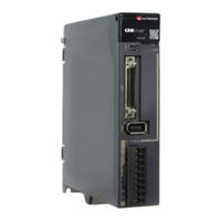
Unitronics UMD-0000B User Manual (285 pages)
Brand:
Unitronics
| Category:
Servo Drives
| Size: 17 MB
Table of Contents
About this Manual
2
Purpose
2
Terms and Abbreviations
2
Symbols
4
General Precautions
5
Safety Precautions
5
Installation Precautions
6
Storage Precautions
6
Wiring Precautions
6
Disposal Precautions
7
Maintenance Precautions
7
Operation Precautions
7
Table of Contents
8
Chapter 1 UMD-B5 Servo Drive
10
Product Features
10
Interpreting the Nameplate
11
Model Designations
12
Part Names
13
Ratings and Specifications
19
External Dimensions
22
System Configuration
23
Chapter 2 Installation
28
Installation Precautions
28
Mounting Types and Orientation
28
Mounting Hole Dimensions
29
Mounting Interval
30
Chapter 3 Wiring and Connecting
32
Precautions for Wiring
32
Countermeasures against Noise
33
Noise Filters
33
Cable Fixing
36
Basic Wiring Diagrams
37
Terminals Arrangements
40
Wiring the Power Supply to Drive
45
Terminals Arrangement
45
Minimum Value
49
Connection Terminals
49
Wiring Procedure
51
Wiring the Encoder
58
I/O Signal Connections
60
Signal Diagram
60
Pin Layout
60
Wiring Description
62
USB Communication Cable
65
Connection Diagram
65
Cable Description
65
Chapter 4 Basic Settings
66
Panel Operator
66
Key Names and Functions
66
Basic Mode Selection
67
Status Display Mode
67
Display Information
69
Parameter Setting Mode
70
Monitor Mode
74
Utility Function Mode
76
Chapter 5 Application Functions
82
Power Supply
82
Motor Rotation Direction
83
Overtravel Limit
83
Function Description
83
Motor Stopping Methods
85
Holding Brake
86
Brake Operating Sequence
88
BK (Brake) Signal
88
Encoder Settings
91
Multiturn Limit Setting
91
IO Signal Allocation
94
Input Signal Allocations
94
Output Signal Allocations
96
Control Mode Selection
97
Speed Control
99
Soft Start
102
Parameter Name
102
Setting Description
102
Zero Clamp Function
103
Position Control
105
Connection Example
107
Electronic Gear
109
Reference Pulse Inhibit Function (INHIBIT)
113
Torque Control
114
Speed Limit During Torque Control
119
Internally Set Speed Control
121
PCP Control
124
Position Command
127
Halt Command
128
Software Limits
129
Selection of Control Mode Combinations
131
Torque Limit
134
Internal Torque Limits
134
External Torque Limits
134
Homing
138
Function Overview
138
Related Parameters
139
Other Output Signals
144
Rotation Detection Output Signal (/TGON)
145
Chapter 6 Canopen Communication
146
Position Control Function
146
Homing Mode
150
Control Word of Homing Mode
150
Status Word of Homing Mode
150
Homing Methods
155
Torque Limit Function
162
Digital Input /Output
163
Functions of Touchprobe
165
Soft Limit Function
170
Chapter 7 Trial Operation
171
Preparations for Trail Operation
171
Inspections and Confirmations
171
Motor Operation Without a Load
171
Applicable Tools
172
Jog Operation
172
Motor Operation with a Load
174
Operation Procedure
175
Program Jogging
176
Operation Description
177
Relevant Parameters
178
Chapter 8 Tuning
180
Overview
180
Basic Conception
180
Control Block Diagram
181
Tuning Process
182
Tuning Modes
183
Function Description
183
Application Restrictions
184
Manual Tuning
187
Adjustment Method
188
Tuning Tools
189
Feedback Speed Selection
193
Vibration Suppression
194
Notch Filter
194
Automatic Vibration Suppression
198
Diagnostic Tools
199
Chapter 9 Alarm Displays
201
Alarm Classifications
201
Alarm Detailed
202
Operation
206
Multi-Turn Data Overflow
211
Chapter 10 Parameters
222
Interpreting the Parameter Lists
222
Parameters Detailed
223
Advertisement
Unitronics UMD-0000B User Manual (217 pages)
Brand:
Unitronics
| Category:
Servo Drives
| Size: 7 MB
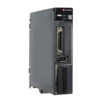
Table of Contents
About this Manual
2
Terms and Abbreviations
2
Symbols
4
Safety Precautions
5
General Precautions
5
Storage Precautions
6
Installation Precautions
6
Wiring Precautions
6
Operation Precautions
7
Maintenance Precautions
7
Disposal Precautions
7
Table of Contents
8
Chapter 1 UMD-E5-S Servo Drive
12
Product Features
12
Interpreting the Nameplate
13
Model Designations
14
Part Names
15
Ratings and Specifications
20
Dimensions
23
System Configuration
27
Example Diagram
27
Minimum System Configuration
30
Peripheral Devices Specification
31
Part Numbers
32
Chapter 2 Installation
34
Installation Precautions
34
Mounting Types and Orientation
34
Mounting Hole Dimensions
35
Mounting Interval
36
Chapter 3 Wiring and Connecting
37
Precautions for Wiring
37
General Precautions
37
Countermeasures against Noise
38
Noise Filters
38
Grounding
41
Cable Fixing
41
Basic Wiring Diagrams
42
Terminals Arrangements
44
Wiring the Power Supply to Drive
50
Terminals Arrangement
50
Wiring a Regenerative Resistor
54
Wiring Procedure
56
Motor Connection Diagram
58
Power Input Wiring Specifications
59
Power Input Wiring Example
59
Wiring the Encoder
61
Connection Diagram
61
Battery Case Connection
62
I/O Signal Connections
63
Signal Diagram
63
Pin Layout
63
Wiring Description
64
Holding Brake Wiring
66
Touch Probe Wiring
66
Communication Connections
67
USB Communication Cable
68
Chapter 4 Basic Settings
69
Panel Operator
69
Key Names and Functions
69
Basic Mode Selection
70
Status Display Mode
71
Parameter Setting Mode
73
Monitor Mode
76
Utility Function Mode
78
Chapter 5 STO
84
Introduction
84
Block Diagram
84
Functions and Features
85
Risk Assessment
85
Alarms
86
Environmental Conditions
86
Applicable Standards
87
Terminals Arrangement (CN6)
87
Function Description
89
EDM (External Device Monitor)
89
Safe State
89
S-RDY (Servo Ready Output) Signal
90
BK (Brake Ouput) Signal
91
Stopping Methods
91
Reset Method for Deviation Counter
91
Safety Function Device Connection
91
Disconnecting a Safety Function Device
91
Connecting a Safety Function Device
93
Procedure
94
Chapter 6 Application Functions
95
Power Supply
95
Motor Rotation Direction
95
Overtravel Limit
96
Function Description
96
Connecting the Overtravel Signal
96
Enabling/Disabling the Overtravel Signal
97
Settings for E-STOP
97
Signal Distribution
97
Motor Stopping Methods
99
Motor Stop Methods for Gr.1 Alarms, Safety State and Servo off
100
Motor Stop Methods for Overtravel
100
Motor Stop Methods for Gr.2 Alarms
100
Reverse Brake Torque Limit Setting
101
Holding Brake
101
Function Description
101
Brake Operating Sequence
102
BK (Brake) Signal
102
Output Timing of /BK Signal When Motor Is Stopped
103
Output Timing of /BK Signal When Motor Is Operating
104
Encoder Setting
104
Absolute Encoder Selection
104
Encoder Alarm Resetting
104
Multiturn Limit Setting
105
Encoder Pulse Dividing Output
106
I/O Signal Allocations
107
Input Signal Allocations
107
Default Input Signals
108
Output Signal Allocations
109
Torque Limit
110
Internal Torque Limits
110
External Torque Limits
112
SEMI F47 Function
113
Chapter 7 Ethercat Communications
115
Introduction
115
Specification
115
Communication Indication
115
RUN Indicator
116
Ethercat Slave Information
117
Ethercat State Machine
118
Operation
118
Communications between Master and Slave
119
Distributed Clock
119
Relevant Settings
119
Chapter 8 Cia402 Drive Profile
120
Device Control
121
Cia402 State Machine
121
Stop Modes
123
Homing
125
Homing (HM) Mode
125
Homing Methods
128
Torque Limits
133
Digital and Remote I/O Signals
133
Touch Probe
135
Soft Limit Function
140
Chapter 9 Trial Operation
141
Preparations for Trail Operation
141
Inspections and Confirmations
141
Motor Operation Without a Load
142
Preparations
142
Applicable Tools
142
JOG Operation
142
Motor Operation with a Load
143
Precautions
143
Preparations
144
Operation Procedure
144
Program Jogging
145
Preparations
145
Operation Description
145
Relevant Parameters
146
Parameter Name
146
Applicable Tools
147
Operation Procedure
147
Chapter 10 Tuning
148
Overview
148
Basic Conception
148
Before Tuning
149
Control Block Diagram
149
Tuning Process
150
Precautions before Tuning
151
Tuning Modes
151
Tuning-Less
151
Function Description
151
One-Parameter Auto-Tuning
152
Application Restrictions
154
Manual Tuning
154
Adjustment Method
155
Tuning Tools
157
Auto-Tuning Tool
158
Feedback Speed Selection
162
Vibration Suppression
163
Notch Filter
163
Parameter Setting
163
IF (Intermediate Frequency) Vibration Suppression
164
Load Oscillation Suppression
165
Automatic Vibration Suppression
166
Diagnostic Tools
167
Load Inertia Identification
167
Chapter 11 Alarm Displays
169
Alarm Classifications
169
Troubleshooting Methods
169
Gr.1Alarm
169
Warnings
185
Chapter 12 Parameters
187
Interpreting the Parameter Lists
187
Parameters Detailed
188
Index Name
188
Advertisement
Related Products
Unitronics UMD-0000B-B5
Unitronics UMD-0001B-B5
Unitronics UMD-0002B-B5
Unitronics UMD-0004B-B5
Unitronics UMD-0007CU-B5
Unitronics UMD-0001B
Unitronics UMD-0002B
Unitronics UMD-0004B
Unitronics UMD-0007CU
Unitronics UMD-0010CU-B5
Unitronics Categories
Controller
I/O Systems
Control Unit
Network Router
Recording Equipment
More Unitronics Manuals
Login
Sign In
OR
Sign in with Facebook
Sign in with Google
Upload manual
Upload from disk
Upload from URL